


LumInsight IoT Gateway and Base Station – Ethernet
Rev. B (July 2018)
Setup Guide (Network Configuration)
1
078-1074-01B
LumInsight IoT Gateway and
Base Station – Ethernet
Setup Guide (Network Configuration)
Models 100150-201 and 100150-281
Introduction
LumInsight IoT Gateway and Base Station are a set of
Echelon’s Edge Servers for use with the LumInsight 2
Central Management System (CMS). The Gateway or
Base Station manages a network of lighting controllers
and other devices over a LumInsight RF network. The
data from the Gateway or Base Station is back-hauled
over a LAN/WAN or Cellular connection. This guide is
used to set up the LAN/WAN connection.
Setup Guide Overview
This document provides the instructions needed for
network configuration for access by a LumInsight CMS.
The network settings configuration is end-user specific
and requires the appropriate IP address, Netmask, and
Default IP Gateway to be obtained from the IT staff at the
location where the Ethernet Gateway will be installed. A
LumInsight IoT Gateway Network Information Request
(NIR) Form
must be completed by the customer’s IT staff.
Information about the NIR form is provided at the end of
this guide.
Parts and Accessories
The following parts and accessories are required for the
LumInsight IoT Gateway and Base Station network
configuration:
•
Desktop or laptop (recommended) computer with
an Ethernet port
•
CAT 5 patch cable
•
LumInsight IoT Gateway (Ethernet model number
100150-201) or Base Station (Ethernet model
number 100150-281)
Network Settings Configuration
CAUTION: Make sure that the computer being used is
not connected to any other network and is configured
to receive an IP address from a DHCP server.
To configure the network settings for a LumInsight IoT
Gateway and Base Station, perform the following steps:
1. Open the IP66 enclosure and locate the CloudGate
device inside (refer to the figure below).
CloudGate Device
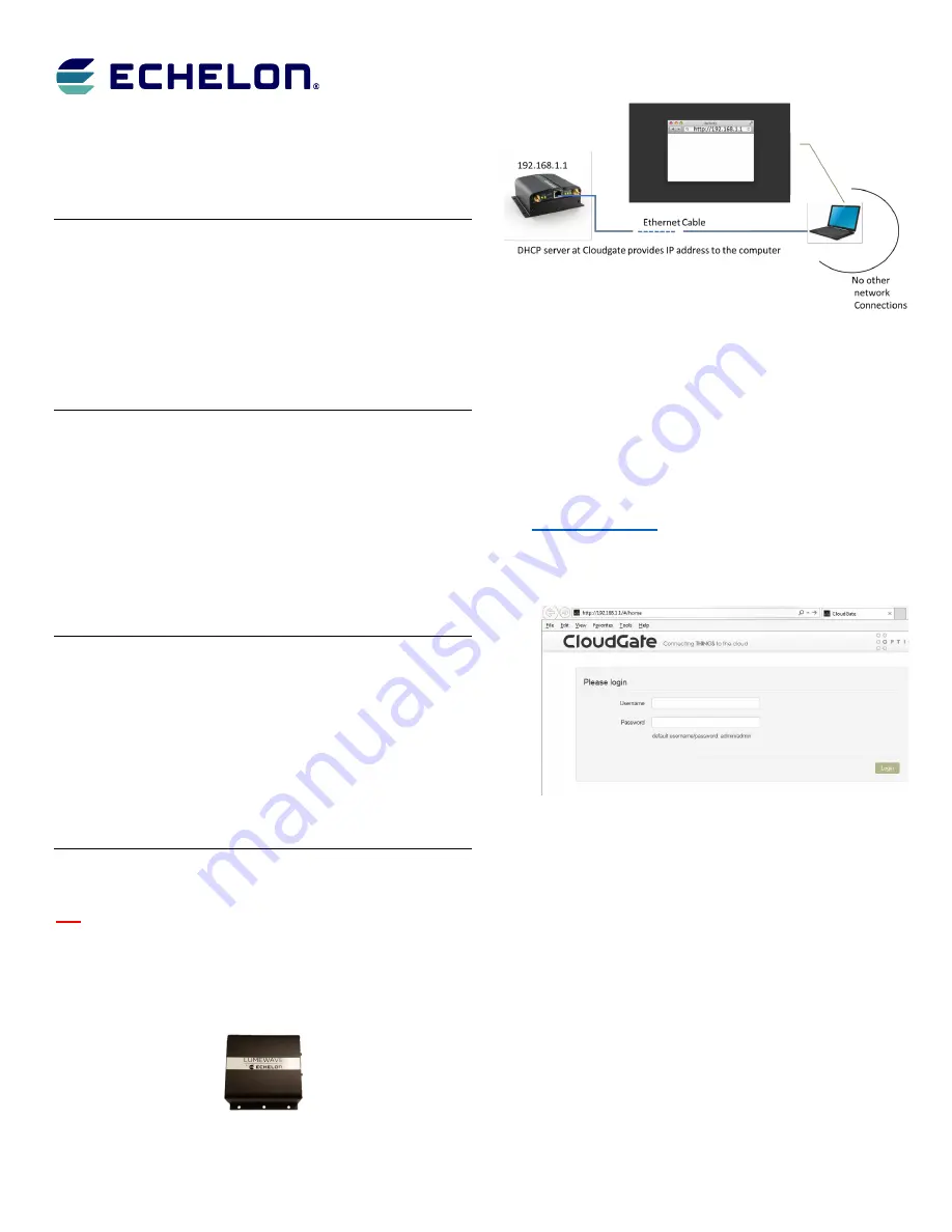
2. Connect one end of the Ethernet cable to the CloudGate.
3. Connect the other end of the Ethernet cable to a
computer (refer to the figure below).
Ethernet Cable Connection
4. Connect the power adapter to the CloudGate and apply
power.
As the CloudGate boots, the system state LED turns
orange;
wait until it turns green
.
When the boot process completes, the computer will
have an active network connection with a valid IP
address.
5. Open a browser window and go to the address
http://192.168.1.1
.
A CloudGate Login page should appear as shown in the
screen below, confirming a good Ethernet connection to
the CloudGate.
CloudGate Login Page
6. Enter the following credentials to login to the CloudGate
web interface:
Username: admin
Password: @Echelon123!
7. On the CloudGate Home page, click on the
Interfaces
menu item and then select the
Main Ethernet
option as
shown
in
the
screen
that
follows.


