Ebyte E01C-ML01SP2, User Manual
The Ebyte E01C-ML01SP2 User Manual is available for free download on our website. Our comprehensive manual provides step-by-step instructions and detailed information about this product. Enjoy the convenience of accessing our user manual online and unlock the full potential of your Ebyte E01C-ML01SP2 device.
Share
Download


Reviews:
No comments
Related manuals for E01C-ML01SP2
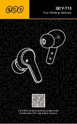
T13
Brand: QCY Pages: 14

TL-WR741ND - Wireless Lite N Router
Brand: TP-Link Pages: 13

DWL-1000AP+
Brand: D-Link Pages: 40

DAP-600P
Brand: D-Link Pages: 46

DAP-3310
Brand: D-Link Pages: 24

DWL-3200A
Brand: D-Link Pages: 23
DWL-3140AP - Web Smart PoE Thin Access Point
Brand: D-Link Pages: 72

DAP-400P
Brand: D-Link Pages: 46

DWL-2130AP - xStack - Wireless Access Point
Brand: D-Link Pages: 12

DBA-1210P
Brand: D-Link Pages: 8

DWL-2230AP - xStack - Wireless Access Point
Brand: D-Link Pages: 12

DWL-2100AP - AirPlus Xtreme G
Brand: D-Link Pages: 2
DWL-1000AP+
Brand: D-Link Pages: 8

DI-713
Brand: D-Link Pages: 5

DWL-3200AP - AirPremier - Wireless Access Point
Brand: D-Link Pages: 113

DAP-3666
Brand: D-Link Pages: 16

DAP-3320
Brand: D-Link Pages: 32

DI-713
Brand: D-Link Pages: 41


