background image


User’s Manual 


X-POS956 


Summary of Contents for X-POS956

Page 1: ...User s Manual X POS956...

Page 2: ......

Page 3: ...anufacturer All trademarks are property of their respective owners Liability Disclaimer In no event will the manufacturer be liable for direct indirect special incidental or consequential damages aris...

Page 4: ...Turn on the device 18 2 RAID Configuration 19 2 1 For Microsoft Windows XP 27 2 2 For Microsoft Windows Embedded POSReady 30 2 3 For Microsoft Windows 7 Windows 8 33 3 Basic Driver Installation 34 3...

Page 5: ...III Wait For Drawer Close 59 Beeper Speaker Configuration 60 Close Cash Drawer Service 61 5 I O Definition 62 4 1 Power Connector 4 2 Serial Port 4 3 Cash Drawer 6 Specification 64...

Page 6: ......

Page 7: ...Chapter 1 1 1 1 Hardware Setup 1 1 Packing Contents 1 X POS956 X 1 4 Drive and Utility DVD X 1 2 Power Adapter X 1 3 Power Cord X 1...

Page 8: ...2 1 2 Quick Tour Front View and Rear View LED Indicator The Power indicator will glow green when power is on Back Panel I O Power indicator HDD Cover MSR Mounting Hole Cover Customer Display Mounting...

Page 9: ...rough the base in the direction as shown below WARNING Before the cable cover is removed please make sure the power is off Power Adapter Connect the DC cable to the DC in jack Computer Mouse and Compu...

Page 10: ...on the back panel of the device another end to your internet device Cash Drawer Connect one end of RJ 12 cable to the Cash Drawer port on the back panel of the device another end to your cash drawer...

Page 11: ...the device and tighten the two M3 screws B Customer Display Power Supply Configuration Caution Never enable the power supply without the customer display installed and be sure to disable the power sup...

Page 12: ...y on your computer keyboard to move to the Advanced tab and then use the or key on your computer keyboard to select Super IO Configuration then press ENTER key 3 Use the or key to highlight the Serial...

Page 13: ...Chapter 1 7 4 Use the or key to select the COM Voltage and the press ENTER key Use the or key to highlight 12V and press ENTER key 5 Press F10 key highlight Yes and press ENTER key...

Page 14: ...er 1 8 MSR 1 Remove the two screws fixing the MSR cover 2 Remove the MSR cover from the device 3 Connect the connectors of the MSR assembly to the device 4 Tighten the two M3 screws to fix the MSR ass...

Page 15: ...ew X 4 C 2nd display support H M4 screw X 2 D Plastic bush I VGA Cable E Plastic spacer Pole Type 2nd Display Kit A 2nd Display 8 4 or 10 G base bracket B 2nd Display Mount H Plastic spacer C 2nd disp...

Page 16: ...item I through the base of the device as shown below 3 Remove the film on the back of the plastic spacer item E and then stick the spacer to the base bracket item F as shown Feed the blue connector of...

Page 17: ...d power input jack of the back I O panel of the 2nd display and then tighten the four M3 screws to fix the 2nd display support onto the 2nd display as shown below 6 Insert the 2nd display onto the bas...

Page 18: ...A cable item L through the base of the device as shown below 3 Remove the film on the back of the plastic spacer item H and then stick the spacer to the base bracket item G as shown Feed the Type A US...

Page 19: ...e B USB connector of the USB cable item K or the black connector of the VGA cable with power connector item L through plastic poles item E and F and install the plastic poles as shown below 7 Feed the...

Page 20: ...le item K or the black connector of the VGA cable with power connector item L to the proper port of the back I O panel of the 2nd display and then tighten the four M3 screws to fix the 2nd display mou...

Page 21: ...Chapter 1 15...

Page 22: ...BIOS before the Windows screen appear 2 Under BIOS screen use the or key on your computer keyboard to move to the Advanced tab and then use the or key on your computer keyboard to select Video Functio...

Page 23: ...Chapter 1 17 4 Use the or key to highlight Enabled and press ENTER key...

Page 24: ...Press F10 key highlight Yes and press ENTER key 1 4 Turn on the device 1 Make sure all peripherals are connected properly 2 Press and hold the power switch until the power indicator on the front pane...

Page 25: ...h the Windows installation disc loaded an external USB floppy disc drive and other accessories are all connected to the X POS 956 properly 1 On a personal computer insert the Driver and Utility DVD in...

Page 26: ...10 1 0 1008_PV Copy a folder into the floppy disc according to the Windows operating system you choose to install 6 Eject the 3 5 floppy disk and insert it into the USB floppy disk drive which is conn...

Page 27: ...al computer keyboard to move to the Advanced tab and then use the or key on your computer keyboard to highlight SATA Configuration and then press the ENTER key 9 Under Advance tab highlight SATA Mode...

Page 28: ...Chapter 2 22 10 Select RAID Mode or AHCI Mode according to your application and then press the ENTER key of the external computer keyboard...

Page 29: ...he F10 key of the external computer keyboard select Yes and then press the ENTER key of the external computer keyboard 12 The screen below shows press the CTRL key and I key of the external computer k...

Page 30: ...apter 2 24 13 Under the MAIN MENU select Create RAID Volume and then press ENTER key of the external computer keyboard 14 Under the CREATE VOLUME MENU highlight the item Name to specify the volume nam...

Page 31: ...Chapter 2 25 15 Highlight the item RAID Level to specify the RAID type RAID0 or RAID1 16 Back to the MAIN MENU select EXIT and then press ENTER key of the external computer keyboard...

Page 32: ...computer keyboard and then press F11 key to enable the system to reboot by external optical disk drive 18 The screen below shows and then switches to the Windows installation automatically Steps below...

Page 33: ...r 2 27 2 1 For Microsoft Windows XP Steps described below are for Microsoft Windows XP series 1 Press the F6 key of the external computer keyboard as soon as the message on the gray bar shows 2 Press...

Page 34: ...on in BIOS Use the or key to select Intel R Desktop Workstation Server Express Chipset SATA RAID Controller If AHCI Mode is selected under the SATA Configuration in BIOS Use the or key to select Intel...

Page 35: ...Chapter 2 29 4 Press S key to continue 5 Setup is loading files 6 Repeat Step 2 Step 3 and Step 4...

Page 36: ...inue Windows XP installation 2 2 For Microsoft Windows Embedded POSReady Steps described below are for Microsoft Windows Embedded POSReady series 1 When the message on the gray bar shows press the F6...

Page 37: ...Chapter 2 31 2 Press ENTER key 3 If RAID Mode is selected under the SATA Configuration in BIOS Use the or key to select Intel R Desktop Workstation Server Express Chipset SATA RAID Controller...

Page 38: ...hapter 2 32 If AHCI Mode is selected under the SATA Configuration in BIOS Use the or key to select Intel R Desktop Workstation Server Express Chipset SATA AHCI Controller 4 Press ENTER key to continue...

Page 39: ...Third Party Storage Drivers Click Next to continue rest steps of Microsoft Windows Embedded POSReady installation 2 3 For Microsoft Windows 7 Windows 8 There is not any special configuration or settin...

Page 40: ...to the USB port and insert the Driver and Utility DVD and turn on the device The program auto runs and displays the DRIVER BANK screen 2 On the DRIVER BANK screen click XPOS 956 Series to enter the dr...

Page 41: ...Chapter 3 35 2 Click Next...

Page 42: ...Chapter 3 36 3 Read the License Agreement carefully and click Yes 4 Click Next...

Page 43: ...Chapter 3 37 5 Click Finish 3 3 VGA Driver Installation 1 On the main screen click VGA Driver...

Page 44: ...Chapter 3 38 2 Please choice your windows OS type Click VGA Driver for Windows XP Windows 7 Windows 8 32bit or 64bit 3 Click Next...

Page 45: ...Chapter 3 39 4 Click Next 5 Read the License Agreement carefully and click Yes...

Page 46: ...Chapter 3 40 6 Click Next 7 Click Next...

Page 47: ...restart your computer later to continue with installing the rest of the drivers Click Finish 3 4 Touch Screen Driver Only for Windows XP Single touch for Windows XP 1 On the driver selection screen cl...

Page 48: ...Chapter 3 42 2 Click QM Touch Panel Driver Windows XP 32bit 64bit 3 Click OK 4 Software Installation Click Continue Anyway...

Page 49: ...Chapter 3 43 5 Hardware Installation Click Continue Anyway 6 Click Exit 3 5 LAN Driver Installation 1 On the main screen click Realtek LAN Driver...

Page 50: ...Chapter 3 44 2 Please choice your windows OS type Click Windows XP Windows 7 Windows 8 32bit or 64bit 3 Click Next button...

Page 51: ...Chapter 3 45 4 Click Install button 5 Click Finish button...

Page 52: ...Chapter 3 46 3 6 Audio Driver Installation 1 On the main screen click HD Audio Driver Please choice Windows operating system type Click Windows XP Windows 7 Windows 8 32bit or 64bit...

Page 53: ...Chapter 3 47 2 The driver is preparing to install Click Next button...

Page 54: ...Chapter 3 48 4 Click Yes to restart the Windows...

Page 55: ...iver Installation 1 On the main screen please Click OPOS Cash drawer sample tool and source code Click OPOS Cash drawer sample tool OPOS Cash Drawer sample too source code Cash drawer user manual Cash...

Page 56: ...Chapter 3 50 Click Next button to install Cash drawer Drver...

Page 57: ...Chapter 3 51 Click Next button Click Install button Click Finish button if OPOS Common OBJ is necessary please check the Insall OPOS CCOS v1 13 Run tome...

Page 58: ...Chapter 3 52 Please wait the OPOS CCO v 1 13 utility initial Click Next button...

Page 59: ...Chapter 3 53 Click Next button Click Next button...

Page 60: ...Chapter 3 54 Click Next button Click Next button...

Page 61: ...Chapter 3 55 Click the Next button to begin the installation Please wait the install progress bar finish...

Page 62: ...exit the installer 3 8 Cash Drawer function introduction Cash Drawer Configuration Before Open Cash Drawer Service please configure the Cash Drawer configuration FireTime It can configuration the volt...

Page 63: ...om L to H Write Status Reverse If the Cash Drawer cannot open or close please click the Write Status Reverse button to change the status From H to L After the config the Cash Drawer setting Open Cash...

Page 64: ...Chapter 3 58 Open Cash Drawer Click the Open Cash Drawer button to open the Cash Drawer box Cash Drawer Status will update if the Cash Drawer box is opened...

Page 65: ...wer button can re check the Cash Drawer box status Cash Drawer Status will show the Cash Drawer box status Wait For Drawer Close If the Cash Drawer box is opened click the Wait For Drawer close button...

Page 66: ...Cash Drawer box is not closed that out of the Open Time Out the buzzer speaker Open Time Out Default is 5000 ms Beep Frequency Default is 1000 ms Beep Duration Default is 1000 ms Beep Delay Default i...

Page 67: ...Chapter 3 61 Close Cash Drawer Service Close Cash Drawer Service It can close the Cash Drawer Service It can click the OK button to exit the OPOS Cash Drawer Test App...

Page 68: ...ut all I O ports as followings 4 1 Power Connector DC Jack Pin Signal Name 1 19V 2 19V 3 GROUND 4 GROUND 4 2 Serial Port COM Port PIN Description PIN Description 1 DCD 6 DSR 2 RXD 7 RTS 3 TXD 8 CTS 4...

Page 69: ...er 4 63 4 3 Cash Drawer RJ12 PIN Description PIN Description 1 GND 4 24V 2 D_OUT0 5 N C 3 D_IN 6 GND Cash Drawer Control Status Address Value Open 280H Bit 4 0 Close 280H Bit 4 1 Read Status 280H Bit...

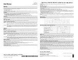
Page 70: ...Chapter 5 64 5 6 Specification...

Page 71: ...DB 9 Pin9 w RI 5V 12V Selectable by BIOS COM 2 5 DB 9 Pin9 w RI 5V 12V Selectable by BIOS COM 3 RS232 internal pin header for MSR COM 6 RS232 internal pin header for Customer Display VGA 1 x DB15 Supp...

Reviews: