INS #
Brand Logo
reversed out of
black
INS #
IB505051EN 049-304
Installation Instructions for the Sure-Lites LPX Combination Exit/Emergency Lights
and Exits with Self Diagnostics
WARNING
Risk of Fire/Electric Shock
If not qualified, consult an electrician.
WARNING
Risk of Electric Shock
Disconnect power at fuse or circuit breaker before
installing or servicing.
Important Safeguards
WHEN USING ELECTRICAL EQUIPMENT, BASIC SAFETY
PRECAUTIONS SHOULD ALWAYS BE OBSERVED INCLUDING
THE FOLLOWING.
1 READ AND FOLLOW ALL SAFETY INSTRUCTIONS
2 Do not use outdoors.
3 Do not use in hazardous locations, or near gas or electric
heaters.
4 Do not let power supply cords touch hot surfaces.
5 Do not use this equipment for other than the intended use.
6 Installation is to be performed only by qualified personnel.
7 Install in accordance with National Electric Code and local
regulatory agency requirements.
8 The use of accessory equipment not recommended by the
manufacturer may cause an unsafe condition.
9 Equipment should be mounted in locations and at heights
where it will not readily be subjected to tampering by
unauthorized personnel.
10 SAVE THESE INSTRUCTIONS
MAX MOUNTING HEIGHT:
17.24 FT
WALL MOUNT INSTALLATION
1 Extend unswitched 24 hour AC supply of rated voltage to
junction box (by others). Leave at least 18 inches of slack.
Circuit should not be energized at this time.
2 Remove the stencil face and lens assembly by applying a
screwdriver to the snaps located at the top and bottom of
the stencil face.
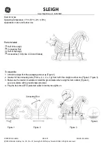
3 Knock out the appropriate mounting pattern and wire pass
hole to match junction box. Use the integrated wire hook
in the backplate to hold the wires in place so that there is
no shadowing on the face of the sign (see Figure 1).
4 Connect power supply and ground in accordance with
local codes. Wire connections as follows: 277VAC/240VAC
line to Orange lead or 120V line to Black lead; Neutral or
240V (Common) to white lead (see Schematic). Cap unused
line lead.
Note:
Connections must be the enclosure rated area of the
frame (top left corner) or junction box (see Figure 1).
5 Mount to junction box.
6 Determine which color sign face is needed. If red is
needed, proceed to step 9
7 If green is the desired color, remove the red lens from
the stencil and replace it with the green lens provided.
(Installation is the reverse of removal.).
8 On the LED circuit board, locate the red/green jumper (See
Schematic).The jumper should be in the red position per
the silk screen printing on the board. Pull gently upward
on the jumper, then shift it one pin over to activate the
green LEDS.
9 If the unit has remote capacity, LED remotes can be
connected using the violet (+) and yellow (-) wires. (See
Schematic).
10 Energize AC supply, LED display will come on.
11 Replace the stencil cover assembly.
12 Remove EZ Key to connect battery. Battery will not charge
with EZ key in place. Allow 24 hours for charging with 120
or 277V input, 48 hours with 240V input.