Eagle T500, Operation Manual
The LG T500 User Manual is essential for getting the most out of this remarkable device. Find this comprehensive manual completely free and available for download from our website. Unlock the full potential of your LG T500 with step-by-step instructions and troubleshooting tips to ensure a seamless user experience.
Share
Download


Reviews:
No comments
Related manuals for T500
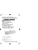
FRESHGUARD VS250
Brand: Black & Decker Pages: 17

BDC8-LA
Brand: Black & Decker Pages: 17

desktop beverage warmer
Brand: Brookstone Pages: 6

VS 110 B10
Brand: ECG Pages: 108

CE23381
Brand: Continental Electric Pages: 4

VP115
Brand: Vacmaster Pages: 16

Astro Pop 2004
Brand: Gold Medal Pages: 10

Hi-pet DHP-12
Brand: Bimar Pages: 25

0900-4000030
Brand: Cresta Pages: 17

BEL 180
Brand: Wexxar Pages: 16

TG1H-1G
Brand: True Pages: 2

TA1HPT-1G-1S
Brand: True Pages: 2

TA2HRT-2S-2S
Brand: True Pages: 2

TA1H-2HG
Brand: True Pages: 2

GMF600
Brand: Gourmia Pages: 8

Freshsaver
Brand: FoodSaver Pages: 6

FSFSSL3460-033
Brand: FoodSaver Pages: 12

FSFRSH0050
Brand: FoodSaver Pages: 38


