


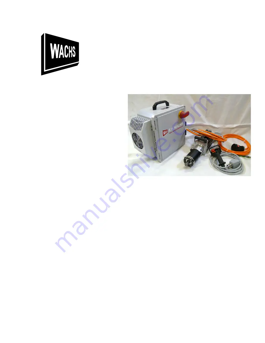
MDSF Servo Electric Drive
User’s Manual
Copyright © 2022 E.H. Wachs. All rights reserved.
This manual may not be reproduced in whole or in part
without the written consent of E.H. Wachs.
E.H. Wachs
600 Knightsbridge Parkway
Lincolnshire, IL 60069
www.ehwachs.com
E.H. Wachs Part No. 69-SERVO-MAN-01
Rev. A, July 2022
Summary of Contents for MDSF
Page 2: ...MDSF Servo Electric Drive 69 SERVO MAN 01 E H Wachs Company...
Page 42: ......


