


4740 W. ELECTRIC AVE. • MILWAUKEE, WISCONSIN 53219 • 414/672-7830 • FAX 414/672-5354 •
www.dingsbrakes.com
Read carefully before attempting to assemble, install, operate or maintain
the product described. Protect yourself and others by observing all safety
information. Failure to comply with instructions could result in personal injury
and/or property damage! Retain instructions for future reference.
DESCRIPTION
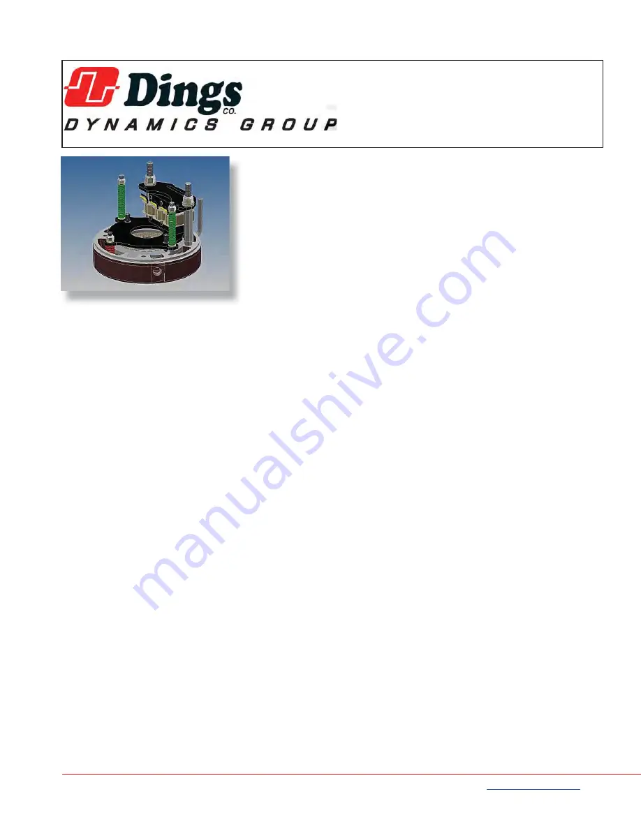
These magnetic disc brakes mount directly onto NEMA182TC, 213TC, and
256TC frame motors, on the end opposite the drive shaft. The brake is direct
acting, electro-magnetically released, and spring set. It uses rotating friction and
stationary disc contact to supply positive braking action. It retains quick release
and setting capabilities at all times.
WARNING: Do not install or use these brakes in an explosive atmosphere.
WARNING
:
Brake performance and features must be carefully matched to the requirements of the
application. Consideration must be given to torque requirements, especially where an overhauling condition
exists, as well as thermal capacity, ambient temperature, atmospheric explosion hazards, type of enclosure
and any other unusual conditions. Improper selection and installation of a brake and/or lack of maintenance
may cause brake failure which could result in damage to property and/or injury to personnel. If injury to
personnel could be caused by brake failure, additional means must be provided to insure safety of personnel.
UNPACKING
When unpacking the brake, inspect it carefully for damage that may have occurred during transit. Do not activate the
manual release without the hub inserted in the discs as doing so may result in loss of disc spline alignment.
GENERAL SAFETY INFORMATION
NOTE: These brakes are not intended for accurate positioning applications. They are designed for applications that
require rapid stopping and holding power, such as on conveyors, door openers, etc.
1. For applications with high inertia-type loads or rapid cycling, the thermal capacity of the brake must be considered.
2. Observe all local electrical and safety codes, as well as the National Electrical Code (NEC) & the Occupational
Safety and Health Act (OSHA).
3. Brake motors & brake gearmotors must be securely & adequately grounded. This can be accomplished by wiring
with a grounded metal-clad raceway system, by using a separate ground wire connected to the bare metal of the
motor frame, or other suitable means. Refer to NEC Article 250 (Grounding) for additional information. All wiring
should be done by a qualifi ed electrician.
4. Always disconnect power before working on or near a brake motor, a brake gearmotor, or its connected load. If the
power disconnect point is out of sight, lock it in the open position and tag it to prevent unexpected application of
power.
5. When working on the brake, be sure the load is completely removed, secured or blocked to prevent injury or
property damage.
6. Provide guarding for all moving parts.
7. Be careful when touching the exterior of an operating motor, gearmotor or brake. It may be hot enough to cause
injury or to be painful. This condition is normal for modern motors, which operate at higher temperatures when
running at rated load & voltage.
8. Protect all electrical lead wires & power cables against contact with sharp objects or moving parts.
9. Do not kink electrical lead wires & power cables, and never allow them to touch oil, grease, hot surfaces, or chemicals.
70 Series 8700 End Mount
Three Phase Brake Instructions
IP56 (NEMA 4) Housing
Bulletin No. BK4773S-3 (6/2017)
R
t
i
a
D
T
2
a
s
a


