Durabrand DCF2703, Service Manual
The Durabrand DCF2703 owner's manual is available for free download at manualshive.com, ensuring you have all the information you need to operate and enjoy this high-quality product. With a comprehensive manual at your fingertips, understanding and optimizing the features of the DCF2703 has never been easier.
Share
Download


Reviews:
No comments
Related manuals for DCF2703
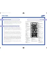
HC-P5256W
Brand: Samsung Pages: 2

CL-21K30M1
Brand: Samsung Pages: 40
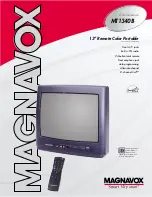
MT1340B
Brand: Magnavox Pages: 2
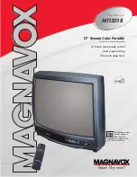
MT1301B
Brand: Magnavox Pages: 2
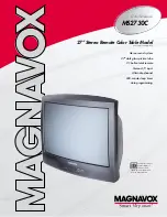
MS2730C - 27i Color Tv
Brand: Magnavox Pages: 2

15MF227B - Hook Up Guide
Brand: Magnavox Pages: 2
3498
Brand: Palsonic Pages: 13
LDS-4371
Brand: Denver Pages: 12

6835TK
Brand: Palsonic Pages: 30

TX-28MD4P
Brand: Panasonic Pages: 31

TX-28LD4P
Brand: Panasonic Pages: 30

TX-28EX4F
Brand: Panasonic Pages: 30

TX-28LD20F
Brand: Panasonic Pages: 36

TX-28LD4DP
Brand: Panasonic Pages: 37

TX-28LD90P
Brand: Panasonic Pages: 56

TX-28EX2F
Brand: Panasonic Pages: 20

UE32F6100
Brand: Samsung Pages: 81

TXM 1367
Brand: Samsung Pages: 48


