Colour Television
TX-28LD4DP
TX-25LD4DP
EURO4 Chassis
SPECIFICATIONS
(Information in brackets { } refers to model TX-25LD4DP)
Power Source:
220-240V AC, 50Hz
Power Consumption:
116W
Aerial Impedance:
75
Ω
unbalanced, Coaxial Type
Stand-by Power
Consumption:
1,8W
Receiving System:
PAL I, PAL 525/60
M.NTSC
NTSC (AV only)
Receiving Channels:
UHF E21 - E69
Intermediate Frequency:
Video
39,5MHz
Audio
33,5MHz, 32,95MHz
Colour
35,07MHz (PAL)
Video/Audio
Terminals:
AV1 IN
Video (21 pin)
1V p-p 75
Ω
Audio (21 pin)
500mV rms 10k
Ω
RGB (21 pin)
AV1 OUT
Video (21 pin)
1V p-p 75
Ω
Audio (21 pin)
500mV rms 1k
Ω
AV2 IN
Video (21 pin) 1V p-p 75
Ω
Audio (21 pin) 500mV rms 10k
Ω
S-Video IN
Y: 1V p-p 75
Ω
(21-pin)
C:0.3V p-p 75
Ω
AV2 OUT
Video (21 pin) 1Vp-p 75
Ω
Audio (21 pin)
500mV rms 1k
Ω
Selectable output (21 pin)
AV3 IN
Audio (RCAx2) 500mV rms 10k
Ω
Video (RCAx1) 1V p-p 75
Ω
Dolby Surround Out
5 x Dolby Surround Out RCA
(Rear)
External Speaker connections
2 x Rear
1 x Centre
1 x External Bass(3D Subwoofer)
High Voltage:
28,5kV
±
1kV
{28,2kV
±
1kV}
Picture Tube:
A66ECF50X41
66cm
{A59ECF50X41
59cm}
Audio Output:
Front Left/Right
2 x 20W
(Music Power)
External Centre
20W
External Bass
26W
Surround
2 x 15W
8
Ω
Impedance
Headphones:
8
Ω
Impedance
3,5 mm
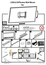
Accessories
supplied :
Remote Control
2 x R6 (UM3) Batteries
TS-600DP Video cabinet / Speaker pack
Dimensions:
Height:
596,5 mm
{550,5 mm}
Width:
778 mm
{730 mm}
Depth:
481 mm
{478,5 mm}
Net weight:
33kg
{27kg}
Specifications are subject to change without notice.
Weights and dimensions shown are approximate.
NOTE: This Service Manual should be used in conjunction with
the EURO4 Technical Guide.
Panasonic CS ( U.K. ) Ltd.
WILLOUGHBY ROAD,
BRACKNELL,
BERKS.,
RG12 8FT.
3DQDVRQLF
ORDER No. SM-98019