background image

N5-Y1071 2002.12

DUPRINTER

Ver.2

DP-460/DP-440
DP-430/DP-340

DP-330/DP-330L

SERVICE  MANUAL

Be sure to read this manual carefully, so that you

repair and service this machine safely and

correctly. Do not begin work until you have

thoroughly understood the contents of this manual.

Repairing or servicing the machine with insufficient

knowledge about it could lead to unforeseen

accidents or falls in the machine's performance or

quality.

DUPLO  SEIKO  CORP.

Summary of Contents for Duprinter DP-330

Page 1: ...lly so that you repair and service this machine safely and correctly Do not begin work until you have thoroughly understood the contents of this manual Repairing or servicing the machine with insuffic...

Page 2: ...chine with insufficient knowledge about it could lead to unforeseen accidents It is not possible to anticipate and describe in a manual such as this every possi ble hazard that could arise in the cour...

Page 3: ...ORTANT NOTE Draws attention to important information If this information is ignored and the machine is operated or serviced incorrectly the machine s performance could drop or it could break down Draw...

Page 4: ...ty ranges are Ambient temperature 10y430y Ambient humidity 40 470 Optimum temperature and humidity 20y 65 If the machine is installed near to faucets water heaters or humidifiers or in cool sunless pa...

Page 5: ...210V AC During platemaking 250W During printing at speed 3 printing speed 230W On standby 60W Power supply voltage Use power supply meeting these requirements 120V AC model 230V AC model With no load...

Page 6: ...The cutter unit contains hazardous sharp blades Exercise great care when inspecting the cutter unit or replacing it or its parts a Otherwise your hands fingers could be injured Do not touch the drum...

Page 7: ...Sticker 4 1 1 View A View A M7 T3060 CAUTION WARNING Do NOT put hands inside machine while it is operating Hands could get caught up or crushed WARNING Do not remove this cover The inside of the print...

Page 8: ...Chapter 8 Chapter 7 Chapter 6 Chapter 5 Chapter 4 Chapter 3 Chapter 2 Chapter 1 HELP Mode Others Troubleshooting Maintenance Check Standard Adjustment Mechanism Description of the Operation Introducti...

Page 9: ......

Page 10: ...Section 171 n Paper Ejection Section 173 m Drum Section 175 Electrical System 179 Option 188 Chapter 6 z Troubleshooting Guide 194 x Error Display 211 Chapter 7 Chapter 8 z Electrical Parts Layout an...

Page 11: ......

Page 12: ...m Setup 18 b Part Names and Their Functions 19 1 Machine exteriors 19 2 Sectional structural view of the machine 22 3 Control Panel 24 n Operation Procedures 26 1 Platemaking Printing 26 2 Multiple Im...

Page 13: ...an be erased r Adjusting the Printing Position vertical In addition to vertical direction adjustment Print the first sheet of paper document size A4R DP 460 24 seconds 1 DP 440 340 19 seconds 1 DP 430...

Page 14: ...ed in the user mode And the power save mode can cut power consumption q Fine Start w Auto Clear e Pre print r Batch Print t Auto Power Off y Auto LCD Off u Long Paper mode OP when mounting the long pa...

Page 15: ...teps 120 ppm 45 120 ppm 5 steps 130 ppm 45 130 ppm 5 steps Print speed 100 Zoom A B size Inch size Preset reduction enlargement 70 81 86 115 122 141 94 Zoom 50 500 Auto zoom 70 81 86 115 122 141 100 P...

Page 16: ...counter 4 built in type Cabinet with front door Cabinet open Power source Domestic 100V 10 50 60Hz 3 0A 120V 120VAC60Hz 2 5A 230V 230VAC50Hz 1 3 A 250W during plate making 230W during 3rd speed printi...

Page 17: ...c Dimensions chap 1 16 44000B cDimensions 790 6 160 790 6 460 390 588 5 1013 9 664 350 186 5 477 5 226 5 483 5 620 1330 mm...

Page 18: ...c Dimensions chap 1 17 MEMO...

Page 19: ...repared on a personal computer can be printed on this machine The PC interface kit is required to connect this machine to a personal computer DDP system NOTE KEYCARD COUNTER 4 Option TAPE CLUSTER 4 Ca...

Page 20: ...switch Document cover Glass Vertical size scale plate Control panel Caster locks Cabinet Optional Feed pressure adjuster lever Feeder guide F Paper feed roller Feeder guide R Paper separator unit Pape...

Page 21: ...ection box lever LED JOG switch 1 Drum rotator switch 1 Master ejection core Master ejection section Master feed section Drum bar Drum handle Drum securing lever Ink puck holder release lever Ink puck...

Page 22: ...ctions chap 1 21 JOG switch 2 Drum rotator switch 2 Paper aligning lever Jump plate Top blow fun Paper stacker guide Paper stopper S2 ADF connector cover Optional Interface kit II Optional Connectors...

Page 23: ...section Master clamp opening closing section Paper feed section Drum driving section Press section Paper ejection section Print tray Drum section 30page 40page 40page 52page 54page 66page 79page 85pa...

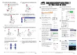
Page 24: ...4 8 2A 2B 2C 44000A1e b Part Names and Their Functions chap 1 23...

Page 25: ...CURRENT SETTING key Shows a list of current setting of the machine SORTER MODE key Switches to sorter mode display MASTER DARKNESS key Switches to Master darkness control display MASTER CONTRAST key...

Page 26: ...isplay IMAGE MODE key Switches to image mode selection display CANCEL key Cancels settings in Special Functions etc and returns to main display CLEAR key Returns the print volume to 0 Other settings o...

Page 27: ...ocedures chap 1 26 nOperation Procedures 1 Pratemaking Printing ZOOM key IMAGE MODE key MULTIPLE EXPOSURE key MASTER DARKNESS key TEST PRINT key 6 BOOK SHADOW ERASER key Selects Text Photograph Text P...

Page 28: ...multiple printing selection key makes a different multiple printing indicator light up in sequence To set the number of images press the key until the indicator for the desired number of images is li...

Page 29: ...7 2 Master End Detection 47 3 Master top sensor 48 4 Master Detect Sensor 49 5 Cutter Unit 50 6 Master Feed Clutch Electromagnetic clutch 51 Master Ejection Section 52 1 Description 52 2 Circuit 52 3...

Page 30: ...otor 83 1 Rotation Speed Control by Encoder Sensor 84 2 Selecting the Speed 84 b Press Section 85 1 Description 85 1 Press Roller Timing Printing Area 85 2 Function of Parts 87 1 P Roll Sensor 87 2 Sw...

Page 31: ...the left or back ward with a stop position of scanner home position sensor PS1 Optical System Operation 440340 When ADF is attached set the ADF Home Position Sensor PS2 as the optical system stop posi...

Page 32: ...g process 1 When the PLATEMAKING key is pressed the optical system will perform shading at home position PS1 and then move to the left 3 After it returns the optical system is then on standby for the...

Page 33: ...he document sensors sense the document s length in the primary scanning and secondary scanning 2When the ADF is installed the document size primary scanning sense for ADF side 2 Reading the Document D...

Page 34: ...w erasing mode can not be used Platemaking Area for the Selected Paper 2The platemaking area varies depending on the selected paper size as shown below When the magnification error is 0 in the primary...

Page 35: ...rrupting plate Slider A Scanner home position sensor PS1 ADF home position sensor PS2 Slider A Photointerrupting plate Photointerrupting plate Photointerrupting plate A shading plate is attached on sl...

Page 36: ...the document glass A3 B4 LG LD A4 LT B5 ST A5 A5R B5R LTR A4R STR STR LTR MINIR MINIR LD LT LG ST MINI A4R A3 B5R B4 A5R A4 B5 A5 MINI A3 B4 LG LD A4 LT B5 ST A5 A5R B5R LTR A4R STR STR LTR MINIR MIN...

Page 37: ...nk CN12 1 1 2 3 1 2 3 3 Light green 2 5V 5V Red 4 4 4 Blue 5 5 5 Green Blue CN12 6 1 2 3 6 7 8 8 Red 7 Gray Blue CN12 9 1 2 3 9 10 11 11 Red 10 5V 5V 5V 0 5V 5V 5V 0 Light blue Pink Light green Red Bl...

Page 38: ...er is opened and sensor is photopassed Document cover position sensor Red Blue CN6 1 1 2 3 22 23 24 3 Light green Red Blue Light green 2 5V 5V 5V 0 Main PCB unit Photopassing 0V Photointerrupting 5V C...

Page 39: ...cification for the CCD Drive PCB unit Lamp inverter unit CN9 9 7 8 9 11 10 CN1 1 3 2 CN12 1 12 CN12 12 CN12 11 1 CN2 1 4 1 2 3 12 1 7 8 9 Gray Brown Blue CCD PCB unit Lamp Document Main PCB unit Circu...

Page 40: ...ne does not work except for the master cut SW and the jog SW unless the scanner unit is closed firmly The machine stops immediately when the scanner unit is open after finishing platemaking if platema...

Page 41: ...of master conveyed to the master clamp section of the drum unit with the master feed clutch ON OFF The end mark sensor starts to detect when the end mark black section printed on the end of the roll m...

Page 42: ...en the Master top sensor is interrupted the master is fed a few steps and stopped If the master lead edge does not reach the master top sensor MASTER SETTING ERROR is displayed Sequence Master cover s...

Page 43: ...to the master clamp section and the sponge roller stops Open the master clamp After the master clamp is closed and clamp the master tip end the drum rotates to roll up the master When the master botto...

Page 44: ...re heated on the image section to make holes on the master film Specifications Circuit 3 Functions of Parts DC DC PCB unit CN2 1 14 Main PCB unit CN5 1 24 CN4 1 6 CN1 1 6 Thermal head 440W07e No DP 46...

Page 45: ...uction month See the table Production year Year of decade A B C D E F G H I J K L Jan Feb Mar Apr May Jun Jul Aug Sep Oct Nov Dec Sign Month NOTE Lot No Thermal resistor line 309 0 5 DP 460 440 309 0...

Page 46: ...001 2713 2767 0110 1010 2768 2823 0110 1011 2824 2879 0111 1000 2880 2935 0111 1001 2936 2990 DP 460 H 44 0000 0001 0010 0011 0100 0101 0110 0111 3825 3908 3909 3993 3994 4077 4078 4162 4163 4246 4247...

Page 47: ...tment of end mark PCB unit Adjust the HELP mode H 07 so the difference between the maximum value of the black level and the white level becomes 20 or more HELP mode H 07 see p 234 Description The end...

Page 48: ...level Master detection sensor 2 When platemaking process is finished before printing process the reflection light amount is in a white level MIN MAX HELP 07 Display value Smaller Larger Reflection li...

Page 49: ...e smaller the light amount is the larger the output voltage is The value is checked with the HELP 05 Description The master top sensor is located at a fixed distance relative to the master By means of...

Page 50: ...or senses master setting errors When a master setting error occurs MASTER SETTING ERROR is displayed While the master is not set to the drum printing will not start even if the PRINT key is pressed In...

Page 51: ...motor for platemaking and the drum stops temporarily the cutter motor is turned on to drive the cutter and the master is cut CN1 1 32 CN9 7 8 Cutter motor M5 Black Red Black Red 1 2 5 6 Drive PCB uni...

Page 52: ...e to be turned by the master as it is wound off the drum 6 Master Feed Clutch Electromagnetic clutch Description Sponge roller2 is attached to the bottom section of the master conveyance way of the ma...

Page 53: ...E appears on the LCD panel Blue Blue Brown Black 7 8 1 2 Eject motor Roll up motor Ejection box sensor Master ejection sensor photo emitting PCB Ejection box full switch Master ejection sensor photo r...

Page 54: ...Photo receiving amount is checked with the HELP06 1 Master Ejection Error Detection Operation While one platemaking is being processed the difference of photo receiving amount is less than 8 by check...

Page 55: ...ain body rear side The master clamp is opened or closed during platemaking Opening closing operation is as follows 5 Rotate the drum to wind the master onto it 4 Open and close the master clamp to hav...

Page 56: ...and C mode Their functions are as follows 1 Structure 2 Operation of Master Clamp Open Close Lever The drawing below is a section through the machine s interior viewed from the control side Master cl...

Page 57: ...aking Master Feed Ejection Section chap 2 2 Master Attach Detach Operation The drum rotates to the master detach position Stop The drum rotates to the master attach position Stop Product No initial lo...

Page 58: ...o d e B m o d e C m o d e The master clamp opening closing lever pinch the master clamp opening closing arm The master clamp is open This state occurs when the master is attach or detach B mode detect...

Page 59: ...hotopassing or photopassing photointerrupting 2C mode When the B mode detect sensor is photopassing the A C mode detect sensor detects the edge of photointerrupting f photopassing 1 A B C Mode Detect...

Page 60: ...master attach simultaneously or when the power returns after it is interrupted Power ON Master detach attach process PLEASE WAIT display Attach detach operation continues PLATE EJECTION ERROR display...

Page 61: ...on the main body rear side The master clamp is opened or closed during platemaking Opening closing operation is as follows 5 Rotate the drum to wind the master onto it 4 Open and close the master clam...

Page 62: ...ns B mode and C mode Their functions are as follows 1 Structure 2 Operation of Master Clamp Open Close Lever The drawing below is a section through the machine s interior viewed from the control side...

Page 63: ...Platemaking Master Feed Ejection Section chap 2 2 Master Attach Detach Operation The drum rotates to the master detach position Stop The drum rotates to the master attach position Stop Product No 0204...

Page 64: ...closing lever pinch the master clamp opening closing arm The master clamp is open This state occurs when the master is attach or detach This state occurs when the PRINT key is pressed B mode detect s...

Page 65: ...etect sensor Clamp motor C mode B mode C mode B mode C mode B mode C mode Master tip end is pulled into the master ejection box Master tip end is fed to the master clamp section Master clamp grips the...

Page 66: ...ch and master attach simultaneously or when the power returns after it is interrupted Power ON Master detach attach process PLEASE WAIT display Attach detach operation continues PLATE EJECTION ERROR d...

Page 67: ...roller Then the pression of the timing roller and guide roller is released by moving the guide roller upward several mm so that the paper is fed through at a speed equal to the circumferential speed...

Page 68: ...ar Paper feed roller When the main motor turns the paper feed cam rotates causing the paper feed segment and timing segment to execute the reciprocating motion shown below which turns the pinion gear...

Page 69: ...2 The paper feed roller is driven by the paper feed stepping motor via the timing belt The rotational timing is controlled by the program 2 Paper Feed Roller Drive Paper feed roller Paper feed steppi...

Page 70: ...eciprocating motion of the timing roller segment is transmitted to the pinion gear and the spring clutch works to rotate the Timing roller in the direction of conveyance 3 Driving of the Timing Roller...

Page 71: ...s gripped with the drum and Press roller 4 Escape the Guide Roller When the timing is too late the printing paper is gripped at two places too long Thus master elongation and slippage occur On the con...

Page 72: ...or feed amount the leading edge of the paper is detected by the paper feed length sensor and paper feed is controlled by program HELP mode H 86 88 HELP mode H 86 88 see p 308 309 If paper feed length...

Page 73: ...follower moves in the direction of e Drive timing of the timing roller becomes earlier Paper timing becomes earlier and the picture image moves backward 2Press the key Cam follower moves in the direc...

Page 74: ...bottom motor rotation The main PCB unit controls the number of top bottom motor rotations with the top bottom encoder sensor signal Operation with the Power ON The printing position returns to the sta...

Page 75: ...440W32e 440354 Blue CN4 1 2 Main PCB unit Drive PCB unit Main PCB unit Light green 5V 5V 5V 5V 4 3 8 CN8 7 Glay Blue 1 2 Paper top detect sensor photo emitting PCB Double feed detect sensor photo rece...

Page 76: ...ched the top limit and triggers stopping of the feed tray s rise Sensing of paper decrease 2As printing progresses and the paper decreases the paper feed roller gradually descends until it obstructs t...

Page 77: ...itch s actuator opening the switch If the elevator encoder sensor does not detect photopassing photointerrupting or photointerrupting photopassing within 2 seconds of sending of the LOWER FEED TRAY co...

Page 78: ...anel 2When absence of paper is sensed platemaking printing and test printing are not possible 2If the paper runs out during printing ADD PAPER is displayed on the LCD panel printing is stopped and the...

Page 79: ...hin 2 seconds of sending of the elevator drive signal the error E002 elevator lock is displayed 7 Long Paper Unit Mechanism Option Circuits Brown White 2 1 Roller motor M CN9 1 2 Drive PCB unit G roll...

Page 80: ...riving Section chap 2 vDrum Driving Section 1 Description Main motor encoder sensor Encoder Main motor Drum gear Drum stop JAM detect position sensor Drum position cam 440320 Master attach detach posi...

Page 81: ...ecked in the above timing with the jam sensor photo receiving and P roll sensor Operation The drum stop JAM detect position sensor is positioned while the drum is rotating as follows 2The drum stop po...

Page 82: ...detected with the edge of photopassing f photointerrupting 2The master set position is detected with the edge of photointerrupting f potopassing 2The drum speed is reduced to the slow before stop spee...

Page 83: ...asses the stop position without reducing the speed Drum rotation 1 switch Drum rotation 2 switch Purple Purple CN4 8 9 5V 5V 0 Light green Light green CN21 5 6 5V 5V 0 1 2 Main PCB unit Circuit 3 JOG...

Page 84: ...Main PCB unit Red Blue Red Brown Brown Blue Blue Blue CN1 1 CN4 1 2 3 4 CN5 1 2 1 2 3 3 Gray 2 5V 5V 5V 0 Main 4 Main 3 Main 2 Main 1 Inter lock monitor Encoder dividing 5V GND CN3 1 CN15 21 22 23 24...

Page 85: ...he HELP01 2 Selecting the Speed The speed is selected with the main 1 4 on the main PCB Unit The following are the speed depending on the pin state Slow 2 is applied to accelerating only it is not use...

Page 86: ...the drum pressed with the press roller the area pressed ON When the pressed on position is 0 under the normally adjusted conditions relations among 1 2 and 3 are as follows Drum gear Press roller Pre...

Page 87: ...curve goes up and down as shown in the figure The timing of drum ON OFF varies depending on the cam curve s up and down The ON position is before the drum hole section so the printing area is not inf...

Page 88: ...ed Operation The P roll sensor position varies depending on the press roller position as follows When the press roller is OFF DOWN photointerrupting When the press roller is ON UP photopassing P roll...

Page 89: ...PRINT key is pressed Circuits Brown Purple 1 2 1 2 Press motor Pressure center switch Green Green 1 2 M CN12 8 9 CN21 1 2 Drive PCB unit Main PCB unit 5V Pressure position switch White White 3 4 3 4 5...

Page 90: ...in the direction of arrow 1 Switch turns from ON to OFF in response to movement in the direction of arrow 2 2Hi contact pressure position Sensed by pressure position switch Switch turns from ON to OF...

Page 91: ...ted paper is removed from the drum and is ejected to the print tray Escape cam Paper stripper finger Paper ejection motor Top blow fan 440323 Paper ejection fan Eject fan encoder sensor Paper ejection...

Page 92: ...sed air transmitted from the air pump is blowed out of this hole to detach the tip end of the paper from the drum To remove the paper from the drum firmly the gap between the tip of finger and the dru...

Page 93: ...Operation During printing the fan blows a constant stream of air at the paper stripper finger from the rear This assists paper stripping and also presses the paper against the ejection belt which stab...

Page 94: ...alled in the top blow fan and the photo receiving PCB in the paper ejection fan unit HIGH with the optical path interrupted LOW with the optical path passing There are two cases of interruption interr...

Page 95: ...drum rotates twice after the paper feed is ordered ON 1 Paper Jam Detection Timing Description Paper jamming is divided into two types PAPER JAM ON THE EJECTION SIDE and PAPER JAM ON THE FEEDER SIDE P...

Page 96: ...atches the printing speed The belt speeds that are set for the various printing speeds are shown in the table below The set speeds can be adjusted using HELP01 Eject fan encoder sensor Red Blue CN2 1...

Page 97: ...ccordance with paper thickness For thinner paper Set the lever in the upper position For thicker paper Set the lever in the lower position Although the lever is usually set at the intermediate positio...

Page 98: ...color inks are available black red blue green and brown Perform color printing to replace the drum unit for each color Press the drum rotation switch to the drum home position to replace the drum unit...

Page 99: ...6 Light green 2 Black CN14 1 4 6 2 5 1 3 M 23V Ink detection PCB unit CN1 3 1 2 Drum limit sensor Red Blue CN21 7 1 2 3 9 Glay 8 5V 5V 5V 0 1 3 15 16 3 5 2 4 4 Photopassing 0V Photointerrupting 5V Dru...

Page 100: ...CB Unit The main PCB Unit controls the motor ON and OFF by this signal When NO INK continues while the drum rotates 20 times the number of drum unit rotations it varies depending on the printing speed...

Page 101: ...D CN1 2 No ink Light out 5V Ink Light up 0V 2Ink detection PCB unit Between the CN12 3 and GND 1 LED Display and Output Signal on the Ink Detection PCB Unit 2When the electric capacity variation betwe...

Page 102: ...displayed on the error display and printing stops At the same time the power for the ink motor is turned off The drum rotates until CHANGE INK is displayed after HIGH is output from the ink detection...

Page 103: ...t such ink insufficiency when in the first printing the machine is equipped with a mechanism for raising and lowering the ink roller Before paper is fed in this mechanism pushes the ink roller against...

Page 104: ...ottom limit position and the motor stops In this position the ink roller is pressed against the drum inner surface and ink will be supplied even if the machine performs printing without paper Ink roll...

Page 105: ...k pack by driving the ink motor Operation The piston performs suction and release operation by moving up and down When the piston moves up it draws ink from the ink pack into the pump When the piston...

Page 106: ...e main body the cam unit covers the pin and is locked firmly The difference of the cam unit prevents the cam unit from being loosened due to the machine vibration When the pin is at the bottom of the...

Page 107: ...t of use and the number of prints last time it was used They ensure clear printing right from the first sheet after platemaking Room temperature of 10 or below can cause insufficient ink supply even i...

Page 108: ...ing the PLATEMAKING key When the sideways stepping motor is rotated clockwise CW the drum is shifted from the drum home position to the plate making position opposite from the control After master set...

Page 109: ...ely When the front cover open is detected during platemaking the machine stops before processing printing Operation When the front cover is closed the lever presses the switch and is closed When the f...

Page 110: ...The TAPE CLUSTER starts to feed the tape from the last 10 sheets for the set A fixed length of the tape is fed and is cut after completing printing the set amount This operation is repeated until the...

Page 111: ...Platemaking Master Feed and Ejection Section 125 Master Feed Section 125 1 Removal of Cutter Unit 125 2 Removal of End Mark Sensor PCB Unit 126 3 Removal of Thermal Head 127 4 Removal of Master Feed U...

Page 112: ...Removal of Outer Frame Right Unit 146 5 Removal of Outer Frame Left Assy 147 6 Removal of Inner Frame 148 7 Removal of Ink Pump 149 8 Removal of Ink Motor 149 9 Removal of Ink Detection PCB Unit 150 1...

Page 113: ...ent cover 440030 440031 Document cover Screws 2 Remove the 2 screws shown Slide the document cover back 1cm and then pull it up to remove it 440032 Front cover 1 1 Open the front cover and take out th...

Page 114: ...ove the Side cover R 1 Press the scanner switch to slide the scanner to its far position 2 Remove the 4 screws indicated then remove the side cover R Remove the Rear cover 1 Remove the document cover...

Page 115: ...L R 2 Press the Scanner switch to slide the scanner to its far position See page 113 WARNING Always remove the power cord plug from the outlet before replacing a PCB Unit 440103 440104 4 Loosen the 2...

Page 116: ...ove the 2 screws indicated then remove the side cover L Screws Side cover L 440038 6 Press and hold the Scanner switch while sliding the scanner all the way in the paper feed direction 440039 Main PCB...

Page 117: ...l Connector Connector 440108 Screws Screws Connector Panel board C 3 Follow the instructions below to remove Panel board A 2 connectors 7 screws Panel board B 2 connectors 6 screws Pull the sliding st...

Page 118: ...e power cord plug from the outlet before replacing a PCB Unit 1 Remove the front cover 2 Remove the 3 screws indicated and remove the bracket 3 Remove the 12 terminals See page 112 440043 9 Removal of...

Page 119: ...Stopper R Cover Screw Screw Shading plate x Scanner Section 440044 24S013 Do not dirt the shading plate Clean it if it is dirty IMPORTANT Vertical size scale plater 1 Remove the vertical size scale p...

Page 120: ...ugh 3 above 2 Disconnect the 2 connectors 3 Remove the 2 spacers indicated and remove the inverter PCB unit See page 118 Reading cover Screw 24S020 Inverter PCB unit 1 Carry out 1 and 2 above 2 Remove...

Page 121: ...ted and remove the scanner R bracket See page 113 See page 118 Do not move Slider A by hand IMPORTANT 6 Remove the 3 screws indicated and remove the lamp unit The lamp is fragile handle it with care I...

Page 122: ...val of Lamp Cord 4 Remove the 4 screws indicated and remove the lamp cord Connector Screws 24S026 Lamp cord 1 Carry out 5 1 through 4 above 2 Remove the cord clamp 3 Disconnect the inverter PCB unit C...

Page 123: ...rew Screw Slider A 24S030 Tool 2 Tool 1 Align opening positions Do not move Slider A by hand IMPORTANT 2 Turn the timing pulley and move Slider A so that the Slider A positioning openings are aligned...

Page 124: ...54 Place in opening Slider B Required items Slider B attachation tool 1 Slider B attachation tool 2 Tool 2 Tool 1 Align opening positions 3 Move Slider B so that the Slider B positioning openings are...

Page 125: ...he removed parts in the reverse order of removal Do not confuse left and right when attaching the slide stoppers IMPORTANT IMPORTANT Reinstallation 1 Perform step 1 through 6 of procedure z 5 Remove o...

Page 126: ...Remove the 4 screws indicated and remove the cover F and R 3 Disconnect the 1 connectors indicated 4 Remove the screw indicated and remove the stopper 5 Open the master cover 6 Remove the 2 screws in...

Page 127: ...en the document receiving tray and take out the master roll 2 Open the master cover 3 Remove the 4 screws and remove the cover 4 Remove the 2 screws 5 Disconnect the connector indicated and the end ma...

Page 128: ...nd take out the master roll 2 Open the master cover 3 Remove the 2 screws indicated and remove the guide plate 4 Remove the screw indicated together with the collar 5 Disconnect the thermal head s 2 c...

Page 129: ...er feed unit See page 127 Master feed unit 1 Open the document receiving tray and take out the master roll 2 Take out the drum unit 3 Remove the front cover See page 112 8 Remove the 2 covers shown in...

Page 130: ...PCB units by removing the 2 screws Master ejection sensor photo emitting PCB unit Screws 1 Loosen the screw indicated to slacken the timing belt 2 Remove the timing belt from the pulley 3 Loosen the...

Page 131: ...H 02 see p 227 See page 114 4 Pull out 3 connectors 5 Remove the sub frame C 6 Remove 3 screws to take out the opening closing unit See page 137 1 Remove the master clamp opening closing unit 2 Loosen...

Page 132: ...opening closing lever and master ejec tion master clamp opening closing lever Then fit the timing belt on Adjust the A B and C modes after the master clamp opening closing unit is attached to the prin...

Page 133: ...levator lower limit switch carry out adjustment of its clearance See page 166 IMPORTANT Reinstallation 1 Removal of Paper Sensor v Paper Feed Section 440109 440110 440067 Paper sensor Connector Screws...

Page 134: ...the paper separa tor unit carry out adjustment of its position IMPORTANT Reinstallation Screw Paper feed shaft Paper feed rollers Set screw Paper separator unit See page 164 2 Loosen the set screw ind...

Page 135: ...ver L 3 Disconnect the 4 connectors 4 Remove the 2 screws indicated then remove the cover 5 Remove the 2 screws indicated then remove the cover B 6 Remove the 2 screws indicated then remove the cover...

Page 136: ...Feed Detect Sensor After reinstalling the double feed detect sensor carry out adjustment of its sensitivity See page 167 IMPORTANT Reinstallation 440146 Screws Connector Photo emitting PCB 440147 Scr...

Page 137: ...front cover 2 Remove the drum unit 3 Remove the rear cover 4 Remove the 5 screws indicated then remove the long paper unit See page 114 See page 112 9 Removal of Long Paper Unit LPU Option 440151 Scr...

Page 138: ...B 1 Remove the rear cover 2 Remove the 5 screws indicated and remove the sub frame B See page 114 Remove the sub frame A 1 Remove the rear cover 2 Disconnect the 2 connectors 3 Remove the 9 screws in...

Page 139: ...e 2 screws indicated and remove the drum gear 440075 6 Remove the 5 screws indicated and remove the driving assy 440076 Links E ring E ring Screws Driving assy 2 Removal of Drum Position Cam 1 Remove...

Page 140: ...er Sub Paper Stripper Finger 1 Open the master ejection box 2 Remove the set screws 3 Remove the paper stripper finger and sub paper stripper fingers from the shaft Paper stripper finger Paper strippe...

Page 141: ...iding in the direction of an arrow 440152 440080 440081 Cover Screw Screw Paper ejection fan unit 3 Remove the 3 screws indicated and remove the cover 440079 Main motor PCB unit Screws Connectors Conn...

Page 142: ...the 2 screws with a driver Paper ejection belts Paper ejection JAM sensor Screws Spacers 5 Removal of Paper Ejection JAM Sensor Photo receiving PCB UNIT 4 Removal of Paper Ejection Belt 1 Remove the...

Page 143: ...nd remove the screw indicated then remove the top blow fan unit remove 1 Remove the top blow fan unit 2 Remove the 7 screws indicated and remove the cover sliding in the direction of an arrow 7 Remova...

Page 144: ...pressure adjustment unit Screw 1 Remove the pressure adjustment unit 2 Loosen the set screw 3 Unscrew the 2 screws in the motor mounting plate and remove the mounting plate with its screws in it 9 Rem...

Page 145: ...istake the bottom end of the screen for the top end IMPORTANT 3 Pass the bottom end screen bar through the screen bottom end side 4 Hold the bottom end screen bar in parallel with the drum and roll it...

Page 146: ...2 screws on the anti operation side to take out the bearing plate 5 Remove the master clamp The master clamp is attached to the base with the magnet See page 144 Adjust the master clamp after install...

Page 147: ...n the outer frame right unit and knob screw 4 Part the outer frame right unit a little and remove 3 connectors 5 Remove the outer frame right unit Reinstallation Do not forget to adjust the rail space...

Page 148: ...crew on the rail to take out the rail 3 Remove the screw on the stay to remove the stay 4 Remove 6 screws 5 Pull out the outer frame left assy with the master clamp open Reinstallation See page 178 IM...

Page 149: ...it with the screw Slide the supporting plate in the direction of arrow 1 so that the supporting plate roller roller unit and roller are in contact with the inner surface of the flange right and tight...

Page 150: ...band to remove the hose 3 Pull out the connector See page 148 4 Remove 4 screw to take out the ink pump 1 Remove the ink pump 2 Loosen the set screw to remove the collar 3 Remove 3 screws to take out...

Page 151: ...Reinstallation Screw Connector Screw 440097new Ink detection PCB unit 10 Removal of Ink Roller Up Down Motor 1 Remove the inner frame 2 Pull out the 2 connectors 3 Remove 2 screws to take out the moto...

Page 152: ...151 MEMO...

Page 153: ...4 2 Adjusting the Paper Separation Pressure 165 3 Adjusting the Elevator Top Limit Sensor 165 4 Adjusting the Elevator Lower Limit Switch 166 5 Adjusting the Double Feed Detection Sensors 167 6 Adjust...

Page 154: ...temaking Start Position 182 1 When the Scanner Is in Use 182 2 When in Online 182 4 Adjusting the Document Reading Darkness 183 1 Adjusting the White Level of the Document Darkness 183 2 Adjusting the...

Page 155: ...gh the bracket opening and fix it in place with 2 nuts There should be a 13mm gap between the screw tip and the bracket 5 Place the wire on the hook side on the pulley 6 Place the wire on the pulley i...

Page 156: ...n the rear and 6 times on the operation side 2 Place the wire on the screw side onto the pulley 3 Place the wire on the front pulley of Slider B 4 Pass the screw through the bracket opening and fix it...

Page 157: ...e set screw to adjust the belt s tension to about 1kg See page 128 NOTE Platemaking Master Feed Section Set screw Timing Belt 440100 1kg For removal of master feed unit Adjustment procedure 1 Lift up...

Page 158: ...spring between D E and F Master Ejection Section A Rubber roller B Driving roller C Inverted roller D Driving roller E Inverted roller F Inverted roller qSpring T L90mm rSpring T B L220mm wSpring T L...

Page 159: ...For basic HELP mode procedures 2 Press and hold down the CURSOR PRINTING SPEED ADJUSTMENT key For as long as this key is held down the roll up motor will rotate in the reverse direction counterclockw...

Page 160: ...t ensure that the master clamp opening closing lever is co centered with the sub frame s positioning holes Tension Screws Position hole Master ejection master clamp opening closing lever Positioning h...

Page 161: ...power off then on again The master clamp switch lever will move into the B mode position and stop there 5 Turn off the power and install the drum to the machine body 6 Open the plate ejection box The...

Page 162: ...ow to return to the previous state 1 Remove the drum 2 Access HELP mode H 02 For basic HELP mode procedures 3 Press and hold down the CURSOR PRINT ING SPEED ADJUSTMENT key until the master clamp open...

Page 163: ...oward C mode position see right 4 Turn the power off then on again The master clamp open close lever will move into the B mode position and stop there 5 Turn off the power and install the drum to the...

Page 164: ...rn the fixing screw indicated to move the C mode shade plate and thereby adjust the clearance This operation adjusts the clearance for both the C mode Do not press the master clamp against the rubber...

Page 165: ...paper separator unit Adjustment procedure When the paper separator unit is installed use the adjustment bolt to adjust the unit so that it moves in direction q without sticking and moves smoothly in...

Page 166: ...page 133 See page 71 NOTE 3 Adjusting the Elevator Top Limit Sensor For description of operation Adjustment procedure 1 Insert a 1mm thick strip of material between the paper feed roller and the pape...

Page 167: ...dimension indicated in the figure at right conforms to the value shown below See page 219 HELP mode H 02 see p 227 See page 132 See page 76 NOTE If the feed length is not the standard value 1 Loosen...

Page 168: ...5 mm 440121 0 5mm Eccentric shaft Screw Timing roller Guide roller 5 Adjusting the Double Feed Detection Sensor For description of operation For removal Adjustment method 1 Access HELP mode H 06 For t...

Page 169: ...key to select the photo graph item 4 Press the key to move the print position Bottom limit adjustment 5 When the numerical value of step 1 release the key and press the PRINT key 6 Compare the printed...

Page 170: ...when the groove in the drum flange is aligned with the stopper If the drum is not adjusted to the standard stop position Adjust the position of the drum stop JAM detect sensor so that the stopper fit...

Page 171: ...master detach position edge 3 Adjust the offset in the alignment of the center axis of the master clamp open close arm and the center axis of the master clamp open close lever NOTE 4 Loosen the screws...

Page 172: ...escription of operation Adjustment procedure 1 Loosen the screw indicated Then move the sensor bracket up down to adjust the press roll so that when it is pushed down to the lowest position by the cam...

Page 173: ...descend move in the direction of the arrow Standard value Open the front cover and check whether the center of the press roll is aligned with the mark made in step 1 NOTE Standard value Item Alignmen...

Page 174: ...turn the main motor shaft Stop turning when the lever s roller is positioned at the bottom of the paper stripper finger cam NOTE Standard value Check that the clearance between the drum surface and t...

Page 175: ...e main motor shaft by hand and stop the press roller at the ON position Standard value Item Clearance between lever and paper stripper finger return stopper about 1mm WARNING Do not touch the drum or...

Page 176: ...the entire surface Adjust the above 1 and 2 at the same time There are 7 settings standard and 3 settings to adjust the printing darkness Print more than ten sheets every time the printing darkness is...

Page 177: ...Loosen set screws 2 on both sides 3 Adjust the gap with the adjusting screws on both sides so that the space on both sides meets the standards After adjustment 1 Tighten set screw 2 2 Tighten set scre...

Page 178: ...1 Cut the master leaving 20mm wide piece at three places both sides and center Have the clamp plate grip the three sections 2 When the resistance for pulling the master out is not stable rotate the cl...

Page 179: ...ighten the set screw to fix the rail 2 Rear side Adjustment procedure 1 Open the rear cover on the main body 2 Loosen the screws on the rail to adjust so that the gap between the roller on the rear si...

Page 180: ...e 1 Prepare a basic document as shown in the figure Draw a line primary scanning at the position 30mm from the top end of the paper and at the position 200mm from the above line DP 460 440 430 A3 pape...

Page 181: ...m the top end of the paper DP 460 440 430 A3 paper DP 340 330 330L B4 paper 2 Place the basic document on the document table to perform platemaking and printing Standard values Compare the size of A s...

Page 182: ...t as shown in the figure from a sheet of paper Draw a 100mm line at the position 30mm from the right end and from the top end of the paper DP 460 440 430 A3 paper DP 340 330 330L B4 paper 2 Compare th...

Page 183: ...age 168 IMPORTANT Adjustment procedure 1 Set the printing position top and bottom direction to the standard 2 Draw a line at the position 30mm from the top end of the document and prepare a basic docu...

Page 184: ...ut the correction value on the keypad 0 or 1 When the processed document gets dirty 0 1 1 1 The white level is corrected down When the thin section of the document is not processed for platemaking 1 1...

Page 185: ...tion amount display 3 Press the key to memorize the correction value 4 Perform platemaking and printing to check the darkness When adjusted with the H 23 by one stage the standard position on the cont...

Page 186: ...ustment Adjustment procedure 1 Access HELP mode H 01 2 Press the and or key to select item 3 Check the speed value displayed The value should be 16rpm If the value is not correct Turn the main motor P...

Page 187: ...layed value to the correct value 5 To set Speeds 2 through 4 repeat steps 2 through 4 above substituting the appropriate speed for Speed 1 in step 2 and making the appropriate settings given below 6 S...

Page 188: ...see p 226 HELP mode H 01 display HELP mode H 01 display HELP 001 Speed check rpm 111 1 Pre stop speed 2 JOG speed 3 Print speed 4 Eject fan speed Speed level rpm HELP 001 Speed check rpm 111 1 Pre st...

Page 189: ...e edge is positioned 1 5 2 0 mm lower than the lower blade 2 At the same time adjust the space with the adjusting washer so that the space of the blades is about 0 5 mm when seen from the top Option 1...

Page 190: ...189 z Guaranteed Periodical Maintenance 190 x Cleaning and Oiling 190 1 Cleaning 190 2 Oiling 190 c Periodical Maintenance 191 1 6 month Periodical Checking 191 5 Chapter 5 Maintenance Check...

Page 191: ...ntenance must be performed after clearing the trouble 1 Cleaning the document 2 Cleaning the document table glass 3 Cleaning the thermal head xCleaning and Oiling 1 Paper shreds Clean with a brush or...

Page 192: ...er brush Thermal head Cleaning Clean with a soft and clean cloth Do not damage the thermal head Platen roller Cleaning Remove paper shreds Do not damage the platen roller Sensor Cleaning Remove dust w...

Page 193: ...192 MEMO...

Page 194: ...MASTER SETTING ERROR is displayed 202 15 Malfunction of Master Feeding Clutch 203 16 Malfunction of Master Stepping Motor 203 17 PLATE EJECTION ERROR is displayed 204 18 Malfunction of Roll up Motor 2...

Page 195: ...205 202 202 208 209 204 207 206 Massage Remarks Page No Lamp does not Light Up Malfunction of Master Feeding Clutch Malfunction of Master Stepping Motor Malfunction of Eject Roll up Motor Optical Syst...

Page 196: ...e PCB Unit 3 Does the lamp light up when the drive PCB unit CN9 9 produces a short cir cuit to GND YES Follow the procedure 5 Drive PCB Unit 4 Is the cause cleared by replacing the drive PCB Unit YES...

Page 197: ...driving wire and timing belt attached properly NO Attach the wire and timing belt properly There is a foreign object on the optical system moving way 2 Is the rail clean Does the optical sys tem move...

Page 198: ...levator motor Drive PCB Unit 5 Is the cause cleared by replacing the drive PCB Unit YES Finish Elevator motor NO Replace the elevator motor Main PCB Unit 6 Measure the voltage between the main PCB Uni...

Page 199: ...power supply Follow the procedure 4 YES 198 zTroubleshooting Guide chap 6 5 E005 is displayed 6 E006 is displayed Cause Detective section Procedures Result Countermeasure Items to be checked 1 Does c...

Page 200: ...between the I F PCB unit CN4 and the P memory PCB CN3 If OK replace the main PCB unit In platemaking measure the voltage between the regulated power supply S 24 and S GND with the tester Is it 24V Ca...

Page 201: ...oltage Is voltage normal NO Replace thermal head position sensor Main PCB Unit YES Check the bundled wire If OK replace the main PCB unit 10 E013 is displayed Replace scanner home position sensor Caus...

Page 202: ...016 is displayed Replace drum limit center sensor Cause Detective section Procedures Result Countermeasure Items to be checked 1 Does drum shift motor turn when it is checked using HELP02 YES Follow t...

Page 203: ...nsor unit by HELP mode H 07 If un able replace end mark sensor PCB unit VR must be adjusted after replacement of end mark sensor PCB unit Master feeding clutch 2 NO Refer to 15 Malfunction of master f...

Page 204: ...between drive PCB unit CN9 5 and 6 GND show 24V when master feeding clutch is turned on Is trouble cleared by replacing drive PCB unit 16 Malfunction of Master Stepping Motor Cause Defective section P...

Page 205: ...rred Are there any foreign matter or dirt between the master ejection sensor photo receiving and the master ejec tion sensor photo emitting PCB Is trouble cleared by replacing the master ejection sens...

Page 206: ...t indicate 1 when paper is absent and 0 when paper is present Cause Defective section Procedures Item to be checked Result Countermeasure Front cover SW position 1 NO Adjust front cover SW position Fr...

Page 207: ...t Is the scanner switch pressed when document receiving tray is closed When the scanner switch is checked with volt ohm milliammeter does it CLOSE if switch is pressed and OPEN if released Cause Defec...

Page 208: ...ink left in drum Has ink reached detection needle for the ink detection PCB unit Does ink pump operate Is trouble cleared by cleaning inside of ink pump Does voltage between regulated power supply S 2...

Page 209: ...tion sensor If necessary replace Main PCB unit YES Replace main PCB unit Is printing paper long within specified value When JAM sensor 1 is checked with HELP mode H 06 is 0 displayed if sensor is phot...

Page 210: ...05 see p 230 Cause Defective section Procedures Item to be checked Result Countermeasure 1 YES Finish Main PCB unit 2 YES Replace the main PCB unit P roll sensor position 3 YES Finish P roll sensor 4...

Page 211: ...imit Paper slant is large causing creases During printing paper feed errors often occur immedi ately before or after paper tray rises Perform elevator top limit sensor adjustment Paper feed amount If...

Page 212: ...roller segment gear will not return correctly causing reduction of feed amount or disappearance of leading edge margin As a result paper will scrunch up Clean timing roller clutch Repair if necessary...

Page 213: ...is defective During on line master making communication error occurs between P memory PCB unit and I F PCB B unit During on line master making communication error occurs between main PCB unit and I F...

Page 214: ...hapter 7 HELP Mode Pz HELP Mode List 214 x Overview 218 c HELP Mode Functions and Operation Procedures 219 1 Accessing HELP Modes 219 2 Guide to the HELP Mode Descriptions 219 HELP Mode Descriptions 2...

Page 215: ...sition Drum stop position 1 Function testing Lamp ON OFF Motor Scanner ADF 1 Checking Document size Document density level 1 Checking Shading memory Synchronous signal Thermistat temperature Time laps...

Page 216: ...tting Master ejection failure detection Default Sort mode 1 Pre print setting 1 Text mode white level setting 1 Scanning start position setting Document memory Adjustment specification Adjustment spec...

Page 217: ...splay to 6 Paper feed setting of the user settings Adjustment specification Adjustment specification Adjustment specification Adjustment specification Function test 284 1 Main PCB unit sorter port ope...

Page 218: ...stment specification 306 1 Setting 1 Tape cluster length selection of long tape motor selection Setting 2 Tape cluster length selection of short tape Adjustment specification 305 1 Setting After maste...

Page 219: ...justments and appropriate settings must be made after the battery PCB unit is replaced and after initialization setting has been implemented using HELP mode H 27 Modes for function checks These modes...

Page 220: ...ollowing pages are laid out as follows References to related pages LC display for function Operation procedure for individual functions Main functions NOTE H 03 1 Function testing HELP mode 1 Clutch f...

Page 221: ...rocedures chap 7 1 Functions 1 Displaying ROM versions qAccess HELP mode H 00 and press the PRINT key Displays version of the ROM 2 Operation procedure Accessing HELP modes a See page 219 H 00 1 ROM v...

Page 222: ...held down tPress the 0 numeric key twice to access HELP mode H 00 yPress the PRINT key H 00 2 ROM version upgrading HELP mode iTurn the Power switch OFF oRemove the master ROM from the socket of the...

Page 223: ...d down tPress the 0 numeric key twice to access HELP mode H 00 yPress the PRINT key H 00 3 ROM version upgrading HELP mode iTurn the Power switch OFF oRemove the master ROM from the socket of the P me...

Page 224: ...djust 2 Pre stop speed adjustment 3 JOG speed adjustment 4 Print speeds adjustment 5 Initialization of print speeds 6 Eject fan speeds adjustment 7 Initialization of eject fan speeds 1 Following speed...

Page 225: ...just it with VR1 on the main motor PCB unit a See page 185 If the indicated value does not accord with the recommended value above VR1 Main motor PCB unit 440803 VR2 Main motor PCB unit 440804 3 Adjus...

Page 226: ...Check the indicated speed level HELP 001 Speed check rpm 111 1 Pre stop speed 2 JOG speed 3 Print speed 4 Eject fan speed Speed level rpm 2Use the and or key to adjust the displayed value to within th...

Page 227: ...Access HELP mode H 01 and press the PRINT key wPress the and or key to select the Eject fan speed item a To exit the HELP mode Turn the power switch OFF a To access another HELP mode Enter the desired...

Page 228: ...e Turn the power switch OFF a To access another HELP mode Enter the desired mode number using the numeric keys rPress the STOP key The HELP mode selection display will reappear HELP 002 1 Elevator mot...

Page 229: ...er feed clutch testing qAccess HELP mode H 03 and press the PRINT key wPress the and or key to select the item ePress the or key to test the functioning a To exit the HELP mode Turn the power switch O...

Page 230: ...HELP mode H 04 and press the PRINT key When the PRINT key is pressed the drum will rotate and the ink pump run until the ink sensing PCB unit s LED lamp lights to signal that ink supply is OK When th...

Page 231: ...topassing 1 Photointerrupting 0 Photopassing 1 Photointerrupting 0 Photopassing 1 Photointerrupting 0 Photopassing 1 Photointerrupting 0 Photopassing 1 Photointerrupting 0 Photopassing 1 Photointerrup...

Page 232: ...005 1 B mode detect sensor 1 Master attach detach position 1 Drum stop JAM detect position 1 P roll sensor 1 Encoder sensor pressure 1 Thermal head position sensor 1 Master top sensor 1 Ejection box...

Page 233: ...mal head current monitor factory check PC IN current monitor factory check Paper size 0 Paper size 1 Not used Document top sensor ADF Document sensor 1 ADF Document sensor 2 ADF Document sensor 3 ADF...

Page 234: ...Super capacitor thermister 1 Thermal head thermister 1 Thermal head current monitor 1 PC IN current monitor 1 Paper size 0 1 Paper size 1 Sensors HELP 006 1 Not used 1 Document top sensor ADF 1 Docum...

Page 235: ...detection sensor 1 Functions For electrical parts layout a See page 316 2 Operation procedure Accessing HELP modes a See page 219 1 Checking the condition of the end mark sensor 1 2 qAccess HELP mode...

Page 236: ...light receipt level of the master detection sensor During memorization SAVE 2 Checking the condition of the master detection sensor qAccess HELP mode H 07 and press the PRINT key wCheck the displayed...

Page 237: ...1 Cover SW ADF Switches Value Value a To exit the HELP mode Turn the power switch OFF a To access another HELP mode Enter the desired mode number using the numeric keys wPress the STOP key The HELP mo...

Page 238: ...detach Drum stop position can be checked qAccess HELP mode H 09 and press the PRINT key Each time the PRINT key is pressed the drum stop and jam sensing position sensors and the master removal set pos...

Page 239: ...tor Scanner 2 Stepping motor ADF Movement test ePress the key to test the motor s functioning to right rPress the key to test the motor s functioning to left a To exit the HELP mode Turn the power swi...

Page 240: ...st part 1 Darkest part 111 Central portion Primary scanning Function check 2Primary scanning mm Display of sensed size of document in primary scanning on the document glass 2Secondary scanning mm Disp...

Page 241: ...Any other display indicates abnormality Check of shading memory and display of result 2Two digits will be displayed The first digit represents a count based on the thermal head PCB unit s synchronized...

Page 242: ...1 Master ejection monitor 1 Master roll monitor 1 Factory adjustment Spec setting 2Press the and CLEAR keys The resetting will be memorized Do not turn off the power before the SAVE display has disapp...

Page 243: ...e Enter the desired mode number using the numeric keys wPress the STOP key The HELP mode selection display will reappear 2 Resetting the count of total plates made in user mode qAccess HELP mode H 14...

Page 244: ...movement amount of printing position top bottom qAccess HELP mode H 15 and press the PRINT key The movement amount of printing position top bottom is displayed HELP 015 1 Home position 111 Limit 1 111...

Page 245: ...T 2 Operation procedure Accessing HELP modes a See page 219 qAccess HELP mode H 16 and press the PRINT key HELP 016 Adjustment Specification setting 1111 1 1111 2 eUse the 0 and 1 numeric keys to ente...

Page 246: ...k shadow erasure On line plate making mode setting Following items are indicated 1 A Pre platemaking slider operation enable disable B Thick paper feed setting C D Editing setting 2 A Book shadow eras...

Page 247: ...8 Error setting wPress the and or key to check the item 1 Functions 2The number of occurrences of errors 1 through 8 is displayed Error 1 Paper jam right Error 2 Paper jam left Error 3 Master placing...

Page 248: ...P mode Enter the desired mode number using the numeric keys wPress the STOP key The HELP mode selection display will reappear 2 Resetting of count of total sheets printed in user mode qAccess HELP mod...

Page 249: ...e Start MSDOS r Press and hold down the and PRINTING SPEED ADJUSTMENT keys simultaneously and turn the Power switch on with those keys held down in order to access H 20 t Press the PRINT key y DUPRIN...

Page 250: ...click on N5P111bat communicating MSDOS will boot up C Paratx M8 LPT1 N5P111 hex is displayed on the PC screen DUPRINTER LCD display will change from READY to COPYING PLEASE WAIT 1 While COPYING PLEAS...

Page 251: ...ess HELP mode H 21 and press the PRINT key HELP 021 Checking of communication for ADF Perform a communication check between the ADF and the main board If an error is indicated refer to the Troubleshoo...

Page 252: ...ssion direction setting 1 Setting of master make magnification line progression direction setting H 22 1 Adjustment specification setting HELP mode During memorization IMPORTANT 2 Operation procedure...

Page 253: ...density Scanner 2 Photo mode scan density ADF 1 Photo mode scan density setting H 23 1 Adjustment specification setting HELP mode During memorization IMPORTANT 2 Operation procedure Accessing HELP mo...

Page 254: ...secondary scanning setting H 24 1 Adjustment specification setting HELP mode During memorization IMPORTANT 2 Operation procedure Accessing HELP modes a See page 219 qAccess HELP mode H 24 and press t...

Page 255: ...ted with H 24 1 Scan R E secondary scanning setting ADF H 25 1 Adjustment specification setting HELP mode During memorization IMPORTANT 2 Operation procedure Accessing HELP modes a See page 219 qAcces...

Page 256: ...r 2 Photo mode white level ADF 1 Photo mode white level setting H 26 1 Adjustment specification setting HELP mode During memorization IMPORTANT 2 Operation procedure Accessing HELP modes a See page 21...

Page 257: ...peed and Eject fan speed H 07 End mark sensor value and H 15 movement amount of printing position top bottom readjustments are required as they are initialized IMPORTANT IMPORTANT 2 Operation procedur...

Page 258: ...Buzzer options Key card counter2 2 setting Following items are indicated A Tape cluster B C Buzzer options D Key card counter 2 1 Tape cluster Buzzer options Key card counter2 2 setting H 28 1 Adjust...

Page 259: ...d 1 Functions 1 Adjustment of master infeed amount During memorization IMPORTANT 2 Operation procedure Accessing HELP modes a See page 219 qAccess HELP mode H 29 and press the PRINT key HELP 029 Adjus...

Page 260: ...sible to switch to any other mode To exit this mode turn off the power IMPORTANT ePress the PLATEMAKING key to implement platemaking printing 1 Functions 1 Test pattern Master making printing of Test...

Page 261: ...print setting Use this to set a value for the number of pre print sheets Pre print sheets are extra sheets that are printed at the start of printing without being added to the print count 1 Pre print...

Page 262: ...failure detection Default Sort mode setting Following items are indicated A Not used B First print setting C Master ejection failure detection D Default Sort mode setting 1 Confidential Safeguard Firs...

Page 263: ...owing items are indicated 1 Text mode white level Scanner 2 Text mode white level ADF 1 Text mode white level setting During memorization IMPORTANT 2 Operation procedure Accessing HELP modes a See pag...

Page 264: ...tems are indicated 1 Scanning start position Document memory Scanner 2 Scanning start position Document memory ADF 1 Scanning start position setting Document memory During memorization IMPORTANT 2 Ope...

Page 265: ...ting Following items are indicated 1 Scanning start position Scanner 2 Scanning start position ADF 1 Scanning start position setting During memorization IMPORTANT 2 Operation procedure Accessing HELP...

Page 266: ...ems are indicated 1 Scanning start primary scanning Scanner 2 Scanning start primary scanning ADF 1 Scanning start primary scanning setting During memorization IMPORTANT 2 Operation procedure Accessin...

Page 267: ...are indicated 1 Scanning start secondary scanning Scanner 2 Scanning start secondary scanning ADF 1 Scanning start secondary scanning setting During memorization IMPORTANT 2 Operation procedure Access...

Page 268: ...SAVE display has disappeared 1 Functions 1 Display time selection when entering the number of sets sheets 1 Display time selection when entering the number of sets sheets H 38 1 Adjustment specificat...

Page 269: ...wer before the SAVE display has disappeared 1 Functions 1 Movement setting of Motor Master detection sensor Movement setting 1 A Top bottom motor B Press motor C Ink roller up down motor D Thermal hea...

Page 270: ...e indicated A Not used B Not used C D Outline highlight Scanner 1 Outline highlight setting During memorization IMPORTANT 2 Operation procedure Accessing HELP modes a See page 219 qAccess HELP mode H...

Page 271: ...ion Double feed detection Counter repeat Sorter return timing setting Following items are indicated A Paper size selection setting B Double feed detection setting C Counter repeat setting D Sorter ret...

Page 272: ...1 Default paper option setting During memorization IMPORTANT 2 Operation procedure Accessing HELP modes a See page 219 qAccess HELP mode H 42 and press the PRINT key Display when H 41 is set as follow...

Page 273: ...e the table below for 4 place binary values and the corresponding correction amounts rPress the STOP key The HELP mode selection display will reappear A B C D SAVE H 43 0100 0100 0100 0100 0101 0101 0...

Page 274: ...e displayed Do not turn off the power before the SAVE display has disappeared 1 Functions 1 Offset value for the thermal head drive energy up down During memorization IMPORTANT 2 Operation procedure A...

Page 275: ...o enter a 4 place binary value for the desired correction amount See the table below for 4 place binary values and the corresponding correction amounts rPress the STOP key The HELP mode selection disp...

Page 276: ...Operation procedure Accessing HELP modes a See page 219 qAccess HELP mode H 45 and press the PRINT key HELP 045 Adjustment Specification setting 1111 wUse the 0 and 1 numeric keys to enter a 4 place b...

Page 277: ...Operation procedure Accessing HELP modes a See page 219 qAccess HELP mode H 46 and press the PRINT key HELP 046 Adjustment Specification setting 1111 wUse the 0 and 1 numeric keys to enter a 4 place...

Page 278: ...eration procedure Accessing HELP modes a See page 219 qAccess HELP mode H 47 and press the PRINT key HELP 047 Adjustment Specification setting 1111 wUse the 0 and 1 numeric keys to enter a 4 place bin...

Page 279: ...peration procedure Accessing HELP modes a See page 219 qAccess HELP mode H 48 and press the PRINT key HELP 048 Adjustment Specification setting 1111 wUse the 0 and 1 numeric keys to enter a 4 place bi...

Page 280: ...HELP mode H 49 and press the PRINT key HELP 049 Adjustment Specification setting 1111 wUse the 0 and 1 numeric keys to enter a 4 place binary value for the desired correction amount See the table belo...

Page 281: ...llowing items are indicated 1 Text mode Scan density Scanner 2 Text mode Scan density ADF 1 Text mode Scan density setting During memorization IMPORTANT 2 Operation procedure Accessing HELP modes a Se...

Page 282: ...sappeared 1 Functions 1 Setting of darkness for test pattern platemaking 1 Setting of darkness for test pattern platemaking During memorization IMPORTANT 2 Operation procedure Accessing HELP modes a S...

Page 283: ...DP 10 test pattern 1 line process time setting Following items are indicated A I F switch H 52 B DP 10 test pattern H 52 C D 1 line process time H 52 1 line scan time H 57 1 I F switch DP 10 test pat...

Page 284: ...peration procedure Accessing HELP modes a See page 219 qAccess HELP mode H 53 and press the PRINT key HELP 053 Adjustment Specification setting 1111 1 1111 2 eUse the 0 and 1 numeric keys to enter a 4...

Page 285: ...SORTER a To exit the HELP mode Turn the power switch OFF a To access another HELP mode Enter the desired mode number using the numeric keys rPress the STOP key The HELP mode selection display will re...

Page 286: ...s disappeared 1 Functions 1 Ink check when starting printing Emergency stop Signal jam setting Following items are indicated A Ink check when starting printing B Not used C Emergency stop interlock D...

Page 287: ...e H 56 and press the PRINT key HELP 056 Adjustment Specification setting 1111 wUse the 0 and 1 numeric keys to enter a 4 place binary value for the desired correction amount See the table below for 4...

Page 288: ...ORTANT 2 Operation procedure Accessing HELP modes a See page 219 qAccess HELP mode H 58 and press the PRINT key HELP 058 Adjustment Specification setting 1111 1 1111 2 eUse the 0 and 1 numeric keys to...

Page 289: ...dure Accessing HELP modes a See page 219 qAccess HELP mode H 59 and press the PRINT key HELP 059 Adjustment Specification setting 1111 wUse the 0 and 1 numeric keys to enter a 4 place binary value for...

Page 290: ...PORTANT 2 Operation procedure Accessing HELP modes a See page 219 qAccess HELP mode H 60 and press the PRINT key HELP 060 Adjustment Specification setting 1111 wUse the 0 and 1 numeric keys to enter a...

Page 291: ...s the PRINT key HELP 061 Adjustment Specification setting 1111 1 1111 2 1111 4 1111 5 1111 3 1111 6 eUse the 0 and 1 numeric keys to enter a 4 place binary value for the desired correction amount See...

Page 292: ...ues and the corresponding correction amounts a To exit the HELP mode Turn the power switch OFF a To access another HELP mode Enter the desired mode number using the numeric keys tPress the STOP key Th...

Page 293: ...dure Accessing HELP modes a See page 219 qAccess HELP mode H 63 and press the PRINT key HELP 063 Adjustment Specification setting 1111 1 1111 2 a To exit the HELP mode Turn the power switch OFF a To a...

Page 294: ...SAVE display has disappeared 1 Buzzer tone setting During memorization IMPORTANT 2 Operation procedure Accessing HELP modes a See page 219 qAccess HELP mode H 64 and press the PRINT key HELP 064 Adju...

Page 295: ...rum OP Long Mode setting Following items are indicated A Signal sensor ON OFF B Loop sensor ON OFF C A3 A4 drum OP D Long Mode ON OFF 1 Signal sensor ON OFF Loop sensor ON OFF A3 A4 drum OP Long Mode...

Page 296: ...items are indicated A Double feed detection display setting B Tape cluster OP display setting C A3 A4 drum OP display setting D Long paper mode display setting 1 Double feed detection Tape cluster OP...

Page 297: ...Specification setting 1111 1 1111 2 A B C D SAVE rPress the key The correction amount will be memorized in the battery PCB unit s EEPROM During memorization SAVE will be displayed Do not turn off the...

Page 298: ...ge 219 qAccess HELP mode H 70 and press the PRINT key HELP 070 Adjustment Specification setting 1111 1 1111 2 a To exit the HELP mode Turn the power switch OFF a To access another HELP mode Enter the...

Page 299: ...emorization IMPORTANT 2 Operation procedure Accessing HELP modes a See page 219 qAccess HELP mode H 71 and press the PRINT key HELP 071 Adjustment Specification setting 1111 1 1111 2 eUse the 0 and 1...

Page 300: ...key The correction amount will be memorized in the battery PCB unit s EEPROM During memorization SAVE will be displayed Do not turn off the power before the SAVE display has disappeared IMPORTANT eUse...

Page 301: ...key The correction amount will be memorized in the battery PCB unit s EEPROM During memorization SAVE will be displayed Do not turn off the power before the SAVE display has disappeared IMPORTANT eUse...

Page 302: ...ting Following items are indicated A Initial print density B Initial master density C Initial document mode D Initial print speed 1 Initial print density Initial master density Initial document mode I...

Page 303: ...a See page 219 qAccess HELP mode H 75 and press the PRINT key HELP 075 Adjustment Specification setting 1111 wUse the 0 and 1 numeric keys to enter a 4 place binary value for the desired correction a...

Page 304: ...orization IMPORTANT 2 Operation procedure Accessing HELP modes a See page 219 qAccess HELP mode H 76 and press the PRINT key HELP 076 Adjustment Specification setting 1111 wUse the 0 and 1 numeric key...

Page 305: ...77 Adjustment Specification setting 1111 1 1111 2 a To exit the HELP mode Turn the power switch OFF a To access another HELP mode Enter the desired mode number using the numeric keys tPress the STOP k...

Page 306: ...opy and stop S2 ADF option Drum rotates once at tape insertion timing Drum rotation setting at tape insertion timing setting During memorization IMPORTANT 2 Operation procedure Accessing HELP modes a...

Page 307: ...length selection of long short tape motor selection Following items are indicated 1 Tape cluster length selection of long tape motor selection 2 Tape cluster length selection of short tape 1 Tape clus...

Page 308: ...iming adjustment During memorization IMPORTANT 2 Operation procedure Accessing HELP modes a See page 219 qAccess HELP mode H 85 and press the PRINT key HELP 85 Adjustment Specification setting 1111 1...

Page 309: ...ount will be memorized in the battery PCB unit s EEPROM During memorization SAVE will be displayed Do not turn off the power before the SAVE display has disappeared IMPORTANT HELP 86 Adjustment Specif...

Page 310: ...aper mode adjustment 1 Paper feed timing Long paper mode adjustment During memorization IMPORTANT 2 Operation procedure Accessing HELP modes a See page 219 qAccess HELP mode H 87 and press the PRINT k...

Page 311: ...aper mode adjustment 1 Paper feed length Long paper mode adjustment During memorization IMPORTANT 2 Operation procedure Accessing HELP modes a See page 219 qAccess HELP mode H 88 and press the PRINT k...

Page 312: ...key HELP 095 Adjustment Specification setting 1111 1 1111 2 a To exit the HELP mode Turn the power switch OFF a To access another HELP mode Enter the desired mode number using the numeric keys tPress...

Page 313: ...otograph mode ADF 1 Text photograph mode scanner ADF white level and reading density setting During memorization 2 Operation procedure Accessing HELP modes a See page 219 qAccess HELP mode H 101 and p...

Page 314: ...unctions 314 1 Switches Clutches Solenoids 314 2 Sensors 1 315 3 Sensors 2 316 4 Motors Fans 317 5 PCB unit Others 318 6 Connector VR LED Layout and Functions 319 x Overall Wiring Layout 325 1 Overall...

Page 315: ...er open closed detection Front cover open closed detection Elevator bottom limit Whether the drum is set or not is detected Whether the master ejection core is set or not and full or not is detected S...

Page 316: ...detection Master clamp opening and closing lever A C mode is detected Master clamp opening and closing lever B mode is detected Master set removal position is detected Drum stop position and JAM dete...

Page 317: ...nt position is detected 4 secondary scanning Document position is detected 5 secondary scanning Photo emitting of the master ejection and JAM detection sensor Master is detected at the inlet of the ma...

Page 318: ...ress motor Ink roller up doun motor Thermal head up doun motor Master feed stepping motor Ink pump motor Sideways stepping motor Eject Roll up motor Paper feed stepping motor Guide roller drive motor...

Page 319: ...e on the whole Keeping the total counter and HELP information 24V 12V 5V Controlling the main motor Driving the motor Detecting Ink amount in the drum Supplying with DC power supply Thermal head 1 2 3...

Page 320: ...ir Functions chap 8 6 Connector VR LED Layout and Functions 1 CCD PCB unit N5 V320 2 Inverter PCB unit J2 X105 3 LCD Panel TG014 CCD CN1 CN 2 CN 1 440910 440917 440904 Do not remove the CCD PCB or loo...

Page 321: ...2 SW5 SW8 SW11 SW16 SW22 SW14 SW13 SW15 SW3 SW6 SW9 SW12 SW20 SW19 SW18 SW21 SW17 CN3 CN2 CN1 CXA M10 5 Panel Board B N5 V305 SW7 SW6 SW1 SW2 SW3 SW4 SW5 LED1 LED3 LED5 LED2 LED4 CN2 CN1 6 Panel Board...

Page 322: ...321 z Electrical Parts Layout and Their Functions chap 8 CN 1 7 End Mark Sensor PCB unit M7 V320 CN9 SW1 SW DIP 4 LED1 LED2 LED3 LED4 CN3 CN7 U6 CN8 CN1 CN2 8 P memory PCB unit N5 V322 440919 440921...

Page 323: ...V318 Main PCB unit N5 V341 CN 1 CN 2 10 Battery PCB unit M7 V305 440920 DP 440 430 340 330 330L DP 460 Item OFF OFF Details DIP SW SW1 SW2 Not used Not used OFF SW3 SW4 Not used Not used OFF OFF SW5 N...

Page 324: ...INC CES14 10A N1 VR1 VR2 11 Main Motor PCB unit M7 V323 CN9 CN13 CN12 CN14 CN4 CN1 CN3 CN6 CN5 F2 Q8 D12 CN2 CN7 Q5 U21 U27 U31 U32 CN8 CN10 CN11 F2 312010 250V 10A LITTELFUSE INC CES14 10A N1 VR1 VR...

Page 325: ...TOG CNT PF N AC L VR 14 Regulated power supply UA036 CN1 CN2 CN3 CN4 F1 F1 ULTSC 250V 10A N1 S O C CES6 125V 15A N1 440908 440909 Adjusted at the factory Do not change IMPORTANT 13 DC DC PCB unit 1 N...

Page 326: ...Wiring Layout chap 8 x Overall Wiring Layout Overall Wiring Layout 1 Main PCB 1 2 A C mode detect sensor B mode detect sensor Drum stop JAM detect position sensor Master attach detach position sensor...

Page 327: ...326 x Overall Wiring Layout chap 8 13 Overall Wiring Layout 1 Main PCB 2 2 Master roll cut SW Elevator down SW Master detection sensor Drum center sensor...

Page 328: ...327 x Overall Wiring Layout chap 8 14 2 Overall Wiring Layout 2 Overall Wiring Layout 2 Drive PCB 1 2 O...

Page 329: ...328 x Overall Wiring Layout chap 8 15 Overall Wiring Layout 2 Drive PCB 2 2...

Page 330: ...Reproduction prohibited 1st printing January 2002 2nd printing December 2002 Issued by DUPLO SEIKO CORPORATION PRINTED IN JAPAN...

Reviews:

Related manuals for Duprinter DP-330