background image

559

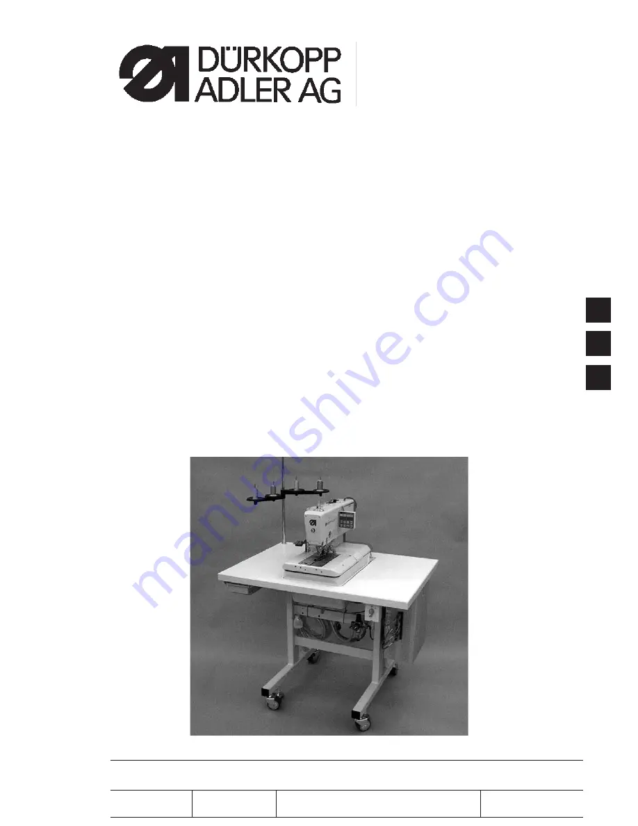
Doppelkettenstich Knopflochautomat

Einfachkettenstich Schnürlochautomat

Automatic double-chainstitch buttonholer

Automatic single-chainstitch eyelet machine

Bedienanleitung / Operating Instructions

Aufstellanleitung / Installation Instructions

Serviceanleitung /

Service Instructions

Postfach 17 03 51, D-33703 Bielefeld

Ÿ

Potsdamer Straße 190, D-33719 Bielefeld

T49 (0) 5 21/ 9 25-00

Ÿ

T49 (0) 5 21/ 9 25 24 35

Ÿ

www.duerkopp-adler.com

1

2

3

Ausgabe / Edition:

Änderungsindex

Teile-Nr./Part.-No.:

07/2007

Rev. index:

01.0

Printed in Federal Republic of Germany

0791 559001

Summary of Contents for 559

Page 1: ...rating Instructions Aufstellanleitung Installation Instructions Serviceanleitung Service Instructions Postfach 17 03 51 D 33703 Bielefeld Potsdamer Straße 190 D 33719 Bielefeld Telefon 49 0 5 21 9 25 00 Telefax 49 0 5 21 9 25 24 35 www duerkopp adler com 1 2 3 Ausgabe Edition Änderungsindex Teile Nr Part No 07 2007 Rev index 01 0 Printed in Federal Republic of Germany 0791 559001 ...

Page 2: ...rty of Dürkopp Adler AG and copyrighted Reproduction or publication of the content in any manner even in extracts without prior written permission of Dürkopp Adler AG is prohibited Copyright Dürkopp Adler AG 2007 Übersicht Summary Bedienanleitung Aufstellanleitung Serviceanleitung Bauschaltplan 9890 580001 B Pneumatikgeräteplan 9770 559001 Operating Instructions Installation Instructions Service I...

Page 3: ... fabric waste Service maintenance inspection repair and or Transport The user also has to assure that only authorized personnel work on the machine The user is obliged to check the machine at least once per shift for apparent damages and to immediatly report any changes including the performance in service which impair the safety The user company must ensure that the machine is only operated in pe...

Page 4: ...ersons with appropriate training 7 For service or repair work on pneumatic systems disconnect the machine from the compressed air supply system max 7 10 bar Before disconnecting reduce the pressure of the maintenance unit Exceptions to this are only adjustments and functions checks made by appropriately trained technicians 8 Work on the electrical equipment must be carried out only by electricians...

Page 5: ...ate 15 8 Clamping plates 8 1 Inserted clamping plates 17 8 2 Aligning the clamping plates as to the fabric support plate 18 8 3 Adjusting the spreading 19 8 4 Height of the fabric clamps 21 8 5 Adjusting the locking sheet 22 8 6 Arrest of the clamping plates 23 8 7 Adjusting the fabric clamping pressure 24 9 Adjusting the seam width 9 1 Presetting the seam width 25 9 2 Needle zero position 26 10 C...

Page 6: ...perations without head cover 49 23 2 Fuses in the control box 50 23 3 Exchange of the control 50 24 Service menu technician level 24 1 Activating the service menu 51 24 2 Selection of a menu item submenu item 51 24 3 Multitest 51 24 4 Quitting the service menu 51 24 5 List of menu and submenu items 52 24 6 Menu items 500 Configuration automatic buttonholer 53 24 7 Menu items 520 Tension data for t...

Page 7: ...ry In case of repair alteration and maintenance work Switch the main switch off Exception Adjustments carried out with the help of test or adjusting programs Adjusting operations and function tests when the machine is running Carry out adjusting operations and function tests of the running machine only under observation of all safety measures and with utmost caution Adjusting operation in the need...

Page 8: ... the eccentrics for the spreaders the loopers and the connecting stitch have to be in staking out position too The positions have been set by the manufacturer in such a way that standard material can be sewn with the 559 If you want to use other needle sizes thread sizes or materials you may have to set positions slightly differing from the staking out position The locking pegs are included in the...

Page 9: ...ut the arm shaft with arresting pin 1 Important In this position the needle bar must be in the top dead center in front of the left entry point Check with the arresting pin 2 whether the looper eccentric 5 and the spreader eccentric 6 can be staked out Correction Stake out the arm shaft with the arresting pin 1 Loosen the screws at the looper eccentric 3 Turn and stake out the eccentric Tighten th...

Page 10: ...sition left entry point the rotary thread take up disc 6 should be in the right position for a needle 4 that is put on the bore hole of the rotary thread take up disc to butt against the right surface 3 Correction Remove the tension plate 1 Loosen the screws on the belt pulley 5 Push the needle 4 through the bore hole in the rotary thread take up disc 6 Turn the rotary thread take up disc until th...

Page 11: ...d in the eccentric 2 should abut in the notching 1 at the arm Turn the arm shaft in such a way that the looper turret is on the right side right entry point Put the arresting pin 4 in the drill hole 3 of the eccentric 2 Check whether the arresting pin 4 abuts in the notching 1 of the arm Correction Loosen the screws at the eccentric 2 Position the eccentric with the arresting pin right on top agai...

Page 12: ...ry point Correction Switch the machine on The machine positions automatically Move the needle bar in the correct position by handwheel right entry point Switch to the technician level For this purpose press the keys P and ç simultaneously Enter code 2548 Press key OK The control switches to the technician level Select menu 603 Press key OK Loosen screw 1 at the switching segment 2 Turn the segment...

Page 13: ...rret 2 with the arresting pin 1 Switch the machine on The machine and the fabric support plate run to their initial position Switch the machine off Check whether the looper turret 2 can be staked out with arresting pin 1 Correction Remove the clamping plates 4 Switch the machine on The machine runs to its initial position Switch the machine off Loosen the clamping screw at the toothed belt wheel w...

Page 14: ...10 5 6 9 10 8 5 7 ...

Page 15: ...te Do not separate the cable from the head cover Switch the machine on The machine runs to its initial position Switch the machine off Stake out the looper turret with arresting pin 2 Position an angle 5 at the right side 6 of the looper turret Check whether the screw 7 at the needle bar guide 8 abuts on the angle Correction Loosen the screws 9 at the toothed belt wheel 10 Turn the needle bar guid...

Page 16: ...12 X1 X2 1 1 4 3 2 ...

Page 17: ...plate is adjusted correctly The distance between reference switch 5 and switch sheet 6 must not exceed 0 5 mm Switch the machine on Press the keys P and ß on the control panel simultaneously Enter code 2548 Press key OK The control switches to the technician level Select the menu 608 with the key Switch the menu on with key OK The machine runs to its initial position Switch the machine off Check t...

Page 18: ...n such a way that the dimensions X1 and X2 are equal Loosen screw 7 Turn the switch sheet 6 to the switch actuation point When turning the switch sheet 6 the switching signals are indicated on the control panel inlet r1 Tighten screw 7 Switch the machine off and on again Let the machine move to its initial position and check the position of the fabric support plate Correction of the distance betwe...

Page 19: ...ont edge 1 of the throat plate support should amount to approx 113 mm The distance between reference switch and switch sheet must not exceed 0 5 mm Switch the machine on Press the keys P and ß on the control panel simultaneously Enter code 2548 Press key OK The control switches to the technician level Select the menu 608 with the key Switch on the menu with key OK The machine runs to its initial p...

Page 20: ... support plate manually to the desired measurement Loosen the screws 5 Set the switch sheet 4 to the switch actuation point When shifting the switch sheet 4 the switching signals are indicated on the control panel inlet r2 Tighten the screws 5 Switch the machine off and on again Let the machine move to its initial position and check the measurement Correction of the distance between reference swit...

Page 21: ...ping plates 1 and 2 should be in the holding groove 4 of the fabric support plate in parallel position and without clearance Inserting and removing must however be fingertip easy Insert both clamping plates and check whether there is as little clearance as possible Remove the clamping plates and check whether this is easily possible Correction Adjust the screws 3 correspondingly 3 17 4 3 2 1 ô 0 ...

Page 22: ... be adjusted in such a way that the distance between clamping plate and fabric support plate 1 is equal everywhere distance X1 distance X2 Put on the right clamping plate Check distance X1 and X2 Correction Insert the right clamping plate Loosen the screw 4 with a hexagonal spanner Turn the eccentric 2 correspondingly Tighten screw 4 Insert and adjust the left clamping plate 18 4 3 2 1 X1 X2 ...

Page 23: ...lamping plates 2 and switch the machine on Press the keys P and F on the control panel simultaneously Enter code 2548 Press key OK The control switches to the technician level Select the menu 601 with the key Switch the menu on with key OK Select the function Y03 closing the fabric clamp Press key OK The fabric clamps close Check whether the distance X amounts to 1 3 mm Select the function Y04 Pre...

Page 24: ... the fabric clamp Press the key OK The fabric clamps close Loosen the screws 6 Set the distance X to 1 3 mm basic adjustment with the hexagonal spanner 5 Tighten the screws 6 Select the function Y04 Press key OK The fabric clamps spread Loosen screw 7 Set the distance X to 0 3 mm with the hexagonal spanner 8 Tighten screw 7 Adjust the left clamping plate as well Note The desired spreading must onl...

Page 25: ...chine switched off Standard checking The distance between the open fabric clamps 2 and 3 should amount to 12 mm Remove the clamping plates Open the clamping plate and test e g with a twist drill Ø 12 mm whether the fabric clamps 2 and 3 have the required distance Correction Adjust the distance with core pin 1 3 21 Ø 12 mm 3 2 1 3 2 ...

Page 26: ...ched off Standard checking The locking sheets 1 must be adjusted in such a way that the stops 3 of the clamping plates abut centrally and as tight as possible Insert the clamping plates Check the position of the locking sheet 1 to the stop 3 Correction Adjust the locking sheet 1 with the special spanner 2 in the accessories 22 2 1 3 3 1 ...

Page 27: ...prox 8 mm thick material is loaded and the clamps are closed Insert the clamping plates Switch the machine on Close the fabric clamps Check at the fabric clamp fixture 1 whether the clamping plate can be minimally lifted Load 8 mm thick material Check at the fabric clamp fixture 1 whether the clamping plate can be minimally lifted Correction Switch the machine off Remove the clamping plates Loosen...

Page 28: ...n such a way that the sewing material is clamped safely and tightly Please observe that the sewing material is not damaged by a too high pressure The standard pressure amounts to 4 bar Correction Switch the machine off and tilt it up Loosen the counter nut 3 at the regulator 2 so that the scale 4 is visible Set the pressure with the hexagonal spanner 1 Tighten the counter nut 3 Check the clamping ...

Page 29: ...h sewing equipment are to be used only with one seam width and so cannot be changed or adjusted either in the sewing equipment configuration When the sewing equipment is changed the sewing width will automatically match the sewing equipment Both sewing width electronical and mechanical must be either both narrow or both wide Under the menu 502 it is possible to check the value of the electronical ...

Page 30: ... equipment the seam width will then be adjusted automatically to match the sewing equipment see table Class Sewing equipment narrow wide 559 151 E1501 E1521 E1502 E1522 E1504 E1524 E1551 E1571 E1553 E1573 E1590 E1595 Correction Unscrew the side cover at the arm 1 Screw out screw 3 Screw the screw in drill hole A or B according to the desired seam width Switch the machine on Attention Danger of bre...

Page 31: ...Notes 27 3 ...

Page 32: ...ease observe the necessary program setting as described in chapter 1 1 Set the wide seam width See chapter 9 1 Insert a short needle Part Number 0558 006066 Adjust the fabric clamps right to the outside See chapter 20 Load a piece of cardboard as sewing material Sew a buttonhole without cutting it open In case of a wide throw the inner stitches of the lip must lie exactly one on top of the other C...

Page 33: ... absolute care that the cutting knife corresponds to the subclass and to the sewing equipment According to the sewing equipment the position of cutting knife 2 and cutting block 1 not in use on the photo can be different Please take care in any case that the correct position of cutting knife and cutting block is adjusted when the sewing equipment is changed on the control panel The position of the...

Page 34: ...osen screw 4 Shift the cutting knife 2 to the front or to the back As a presetting shift the cutting knife to the setting dimension X center of buttonhole eyelet to the groove of the throat plate holder listed in the table below As a fine adjustment shift the cutting knife in such a way that it cuts in the center of the buttonhole shape Tighten screw 4 Loosen screw 6 Position guide 7 close to the ...

Page 35: ...10 2 Adjusting the knife parallel to the cutting block Loosen screws 1 2 and 3 Put the key 4 in the accessories on the hexagonal bolt 5 and twist it Push the cutting block 6 downward 31 3 3 2 1 7 6 5 4 ...

Page 36: ...ing block 3 must be in parallel position to the cutting knife 4 The cutting block stop 5 has to be adjusted so that the knife mark on the cutting block 3 reaches the indicated cutting length Correction Loosen screws 1 Adjust the cutting block 2 laterally to the cutting knife 4 Tighten screws 1 Loosen screw 2 Adjust the cutting block 3 in longitudinal direction to the cutting knife 4 Tighten screw ...

Page 37: ...switched off Standard checking Before the fabric support plate continues transporting the fabric the cutting stamp must be in its upper position In order to avoid a possible collision switch 1 checks the position of the cutting stamp Correcting the height of the switch Loosen screw 2 Adjust the height of switch 1 accordingly Tighten screw 2 33 3 2 1 1 ...

Page 38: ... pressure should be adjusted as low as possible However it has to be adjusted in such a way that the material is safely cut The cutting pressure is coordinated to the different cutting lengths in the program Correction See menu item 601 10 6 Cutting duration Standard checking It is possible to set the cutting duration to avoid an unnecessary long cut on the material to be processed thus allowing a...

Page 39: ...ust be on top right The tip of the left looper must be under the edge 3 of the gauge The tip of the right looper must be under the edge 4 of the gauge The looper points must just abut on the gauge Remove the thread trimmer 9 the throat plate 10 the spreader stops 5 and 8 as well as the spreaders 6 and 7 from the looper turrets Bring the needle bar in position up by turning the handwheel Put the ga...

Page 40: ...ation direction until the needle is in the bottom dead center Measure the distance between the edge 1 and the top edge of needle bar 2 with a slide gauge Scale down the measurement on the slide gauge by 2 7 mm Put the slide gauge with the scaled down measurement on the edge 1 Slowly continue turning the handwheel in rotation direction until the needle bar hits the slide gauge The needle bar is in ...

Page 41: ...edle Loosen the screws at the clamping rings 3 and 4 Adjust the looper position as described by shifting the clamping rings Tighten the screws 3 and 4 It must still be possible to turn the looper turret easily after tightening the screws If the looper points are not at the level of the middle of the needle loosen the screws at the eccentric 5 Turn the eccentric 5 until the looper points are at the...

Page 42: ...tween the edge 1 and the top edge of needle bar 2 with a slide gauge Scale down the measurement on the slide gauge by the looping stroke dimension 2 5 mm Example Looping stroke 2 7 mm 2 5 mm Scale the measurement down by 5 2 mm Put the slide gauge with the scaled down measurement on the edge 1 Slowly continue turning the handwheel in rotation direction until the needle bar hits the slide gauge Cor...

Page 43: ... the handwheel until the left looper point is at the level of the middle of the needle Check the distance between needle and looper point in the following positions 1 Looper point basic position 2 Looper turret manually turned by 90 3 Looper turret manually turned by 180 If the distance between looper point and needle is different in the three positions first align the rotary centers of needle bar...

Page 44: ...2 until the looper point have reached the needle The distance between looper and needle must amount to 0 1 mm The needle guard has been adjusted by the manufacturer In general a readjustment is not required If the needle size changes it may be necessary to re adjust the needle guard correspondingly Correction Loosen the locknut Twist the Allen screw 3 correspondingly Tighten the locknut 40 1 2 3 ...

Page 45: ...spreaders being under spring pressure are held in their end position by the stops 1 and 6 The fork of the left spreader 5 should be exactly above the thread hole of the left looper 4 see illustration opposite and the point of the right spreader 2 centrally above the tip of the right looper 3 see illustration at the bottom of the page Correction For adjusting the distance between spreader and loope...

Page 46: ...tance between spreader plate 2 and spreader shank 1 must be exactly the same as that between spreader plate 2 and spreader shank 3 dimension X1 dimension X2 when the needle is in the bottom dead center for the left stitch Correction Loosen the screws at the clamping rings 4 and 6 Turn the clamping rings in such a way that there is an equal distance of the spreader plates to the spreader shanks Tig...

Page 47: ...ng the sewing process there must be a small distance to the throat plate at the following points Under the sewing material or the closed upper fabric clamps It must be possible for the sewing material to move over the throat plate unhindered Under the lower fabric clamps Above the needle thread knife The needle thread knife must move as closely as possible under the throat plate but without touchi...

Page 48: ...e should cut through the needle thread loop taken up from the right looper at the looper front 5 only If the needle thread loop is cut through on both sides this results in a too short thread end and thus in skipped stitches at the seam beginning In the right final position the needle thread knife must neither be in the thread zone nor touch the spreader stop There must be a distance of approx 0 2...

Page 49: ... the counter nuts 5 and 8 Adjusting the height of the knife Loosen screw 10 Adjust the height of the knife holder 9 correspondingly Swing the knife holder 9 manually to check the free movement Tighten screw 10 again Adjusting the distance to the needle Loosen screw 11 Shift knife 12 Tighten screw 11 3 45 8 7 6 5 12 11 10 9 ...

Page 50: ... and in the eyelet Press key P Select the menu 150 Enter 0 5 Select the menu 162 Set the cutting area to 0 7 Insert the clamping plates Insert a new needle Check the distance between the upper fabric clamp 1 and the needle 2 Correction Loosen screws 3 underside Align the clamp bow 7 with fabric clamp 5 laterally to the needle Tighten screws 3 Loosen screws 4 Align the clamp arm 6 with fabric clamp...

Page 51: ...ngle formed by the spreader Insert and clamp the material Turn the machine manually and check whether the thread controller spring tightens the looper thread firmly and long enough Correction of the spring travel Loosen screw 4 Adjust the stop disc 3 Disc to the right longer spring travel Disc to the left shorter spring travel Tighten screw 4 Correction of the spring tension Loosen screw 5 Adjust ...

Page 52: ...tructions This is only listed in the following table to complete the picture Maintenance work to be carried out Operating hours 8 40 160 500 Automatic buttonholer Remove the sewing dust from the area under the throat plate X Check the oil level X Check and clean the toothed belt X Oil the cutting stamp 1 X Oil the clamp arms 3 at the felt 2 X Oil felt 6 at the cam X Pneumatic system Check the wate...

Page 53: ...onal starting If you want to operate the machine without head cover for adjusting purposes the plug 2 can be put on the connecting cable 3 The plug is in the switch casing 1 Caution Danger of injury Remove the head cover for adjustment work only Exercise utmost caution when making adjustments with the machine running 3 49 3 2 1 ...

Page 54: ...re on the back of the control box Only insert the fuses indicated in the circuit diagram 23 3 Exchange of the control See Part 2 Installation Instructions Assembly of the main switch Assembly of the control Potential equalization Installing the sewing software 50 1 2 ...

Page 55: ...Press key OK The menu item is activated Select the desired submenu item with the keys ñ or ò Example 551 Press key OK The submenu item is activated Press key ï Switch back to the level before in the menu 24 3 Multitest The functions of the Multitest menu input test etc can be reached as described under 28 2 However some functions require that the motors are dead Press the keys P and ï simultaneous...

Page 56: ... 525 Value 5 526 Value 6 550 Configuration operation 551 Push button 552 Brightness of sewing lamp 553 Brightness of the display 554 Keyboard signal 600 Multitest 601 Output test 602 Manual input test 603 Automatic input test 604 Sewing motor test 605 Step motor test 606 ROM or flash test 607 RAM test 608 Running to the reference position 609 Starting continuous operation 610 Checking the setting ...

Page 57: ...on Danger of breakage The throw width must match the mechanical position of the throw eccentric See chapter 2 3 Input 1 Narrow 2 Wide Quit the menu item with the ESC key 24 6 3 Menu item 503 Thread monitor In this menu the needle thread monitor is set The set value means 0 Thread monitor off 1 10 Number of stitches after which the sewing process is aborted because of thread breakage Input 0 14 Sta...

Page 58: ...s are included with the delivery of a new solenoid 24 8 Menu items 550 Configuration operation 24 8 1 Menu item 551 Push button In this menu the function of the push button is converted 1st adjustment 1 Standard Key 1 The clamping plates are opened or closed Key 2 The sewing process only starts with the clamping plates closed 2nd adjustment 2 Key 1 The clamping plates are opened or closed Key 2 Th...

Page 59: ...et The set value means Input 0 3 Standard 2 Quit the menu item with key ESC 24 8 4 Menu item 554 Keyboard signal In this menu the keyboard signal is switched on and off The set value means 0 Keyboard signal off 1 50 Keyboard signal in milli seconds Standard 0 Quit the menu item with key ESC 3 55 ...

Page 60: ...aution Danger of injury Exercise utmost caution when making the output test with the machine running In this menu the individual output elements can be switched Select the desired output element with the keys ñ or ò The current status is shown in the display 0 output inactive 1 output active Press key OK The output is converted Output Designation Y01 Needle thread trimmer Y02 Bobbin thread tension...

Page 61: ...tive Input Designation S09 Push button 1 S10 Push button 2 S11 Foot pedal 1 S12 Foot pedal 2 S13 Foot pedal 3 R0 Sewing motor R1 X axis R2 Y axis R3 Z axis Quit the menu item with key ESC 24 9 3 Menu item 603 automatic input test Caution Danger of injury Exercise utmost caution when making the input test with the machine running With this menu item the function of all input elements is checked If ...

Page 62: ...ed with the related reference switches Attention Danger of breakage Before starting the step motor test remove the clamping plates in any case Caution Danger of injury Exercise utmost caution when making the step motor test Select the corresponding step motor A1 A3 with the keys ï or ð With the keys ñ or ò the step motor runs each 20 steps forwards or backwards On the right of the display the step...

Page 63: ...tem 608 Moving to the reference position In this menu the it is possible to start a reference run This testing program is particularly helpful for the setting of the sewing machine Caution Danger of injury Exercise utmost caution when setting the machine 24 9 9 Menu item 609 Starting continuous operation In this menu item it is possible to start a continuous operation Before the sewing starts a sa...

Page 64: ...of the looping stroke needle stroke needle guard and spreader position Caution Danger of injury Exercise utmost caution when setting the machine Select the menu item 610 by using the key ñ or ò Press the OK key The machine references The display reads 6 1 0 0 0 Insert the locking peg 1 and check whether the peg engages in the groove of the arm shaft In this position the needle bar should be positi...

Page 65: ... 2 Check whether the tip of the left looper 2 points to the middle of the needle If the looper s position needs adjustment proceed as follows Press the F key The machine drives back to position 0 The display reads 6 1 0 9 9 Lift up the sewing machine The screws for the looper setting are now accessible 3 61 2 ...

Page 66: ...ion appears Select the positions one after the other and check their settings Position Setting 1 Setting the locking positions see chapter 2 2 Left looper to the needle s middle see chapter 12 3 Right looping stroke see chapter 12 4 Needle bar height see chapter 13 ATTENTION Contrary to chapter 13 with this setting a position is selected so that the complete needle s eye is to be seen under the le...

Page 67: ...he valve of the respective thread trimming system on 3 the sewing cycle is stopped after switching each valve on Select the desired item with the keys ñ or ò Press the OK key The breakpoint mode will be turned on Press the ESC key The control unit switches back to the main menu Start the testing program through the control panel hand switches or the foot pedal The machine moves to the first breakp...

Page 68: ...ewing motor defective Control defective Eliminate the rough running Replace the sewing motor Replace the control 1058 Sewing motor speed Sewing motor defective Replace the sewing motor 1062 Sewing motor IDMA Autoincrement Malfunction Switch the machine off and on again 1302 Sewing motor current supply fault Encoder cable not connected defective Encoder defective Eliminate the blocking Check Replac...

Page 69: ...upply fault Step motor Y axis blocked Encoder cable not connected defective Encoder defective Eliminate the blocking Check Replace the encoder cable Replace step motor Y axis 2252 Step motor Y axis excess current Step motor Y axis defective Control defective Replace step motor Y axis Replace the control 2253 Step motor Y axis excess voltage Too high mains voltage Check the mains voltage 2255 Step ...

Page 70: ...ctive Eliminate the blocking rough running Replace step motor Z axis Replace the control 2356 Step motor Z axis excess temperature Step motor Z axis moves too heavy Step motor Z axis defective Control defective Eliminate the rough running Replace step motor Z axis Replace the control 2362 Step motor Z axis IDMA Autoincrement Malfunction Switch the machine off and on again 2911 2914 Step motor faul...

Page 71: ...e Inform DA Service 7451 7453 7454 Communication test interface Internal fault Switch the machine off and on again 7452 7455 Communication test interface Line fault Cable test interface defective Internal fault Eliminate the cause of the fault Replace the cable Switch the machine off and on again 7551 7555 7558 7559 Communication control panel interface Internal fault Switch the machine off and on...

Page 72: ...rvice 8252 8254 8256 8258 Boot failure Malfunction Switch the machine off and on again 8351 8801 8805 8806 8890 8891 Infrastructure fault Internal fault Switch the machine off and on again Software update Inform DA Service 9000 9099 Seam description fault Internal fault Switch the machine off and on again Software update Inform DA Service 68 ...

Page 73: ... Check compressed air fluctuations Check all compressed air hoses and connections Display Info 220 Thread breakage Activate the threading mode and thread the sewing thread anew Display Info 500 Threading mode is active Deactivate the threading mode Display Err 501 Deactivate the threading mode Display Err 502 Put on head cover or bridge Skipped stitches The needle is blunt bent or incorrectly inse...

Page 74: ... stroke Looper or spreader are adjusted wrongly Even if no wrong adjustment is to be seen and the above mentioned measures did not lead to an improvement check the opposite points once again Check the adjustments described in the following chapters of the Service Instructions Adjusting the locking positions Adjusting the looping stroke Needle bar height Distance between looper and needle Needle pr...

Page 75: ...tly Check the threading of needle and looper thread see Operating Instructions Thread the needle thread Thread the looper thread The buttonhole is cut open inaccurately The set cutting pressure is too low Increase the cutting pressure see chapter Cutting pressure Too short duty cycle of the cutting stamp Increase the duty cycle See menu item 504 The knife edge is blunt or chipped Insert a new knif...

Page 76: ...ponents Check the motion of the fabric support plate at low speed to find possible collisions The fabric support plate is only heavily movable when the machine is switched off Check all components belonging to the drive of the fabric support plate Faulty rotation of the sewing works The toothed belts are insufficiently tightened Retighten toothed belts or replace them if necessary Toothed belts an...

Page 77: ...ound the problem can in some cases be solved by altering the following parameters Speed reduction Increase of the stitches in the eyelet Reduction of the stitch distance Reduction of overlapping Increase of the stitches in the round tack Reduction of the stitch distance in the straight bartack Reduction of the throw width in the straight bartack see Operating Instructions Altering the buttonhole p...

Reviews: