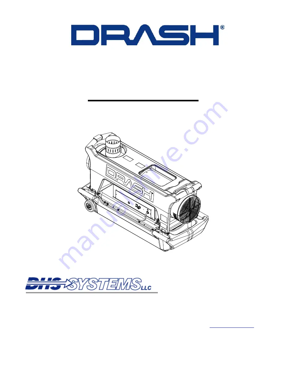
background image


D-1000B HEATER 


Outdoor Use Only 

OPERATIONS & MAINTENANCE MANUAL 


  ISO 9001:   2000 Registered   
 Quality Management System 

33 Kings Highway, Orangeburg, NY 10962 


Phone: 845-359-6066


Fax: 845-365-2114  

          Hotline: 

800-977-3647 

DHS Manual Part Number: 1006395 


Web: www.drash.com  

Revision 

Date: 

01 

APRIL 

2010 

     Email: 


[email protected]


Summary of Contents for D-1000B

Page 1: ...CE MANUAL ISO 9001 2000 Registered Quality Management System 33 Kings Highway Orangeburg NY 10962 Phone 845 359 6066 Fax 845 365 2114 Hotline 800 977 3647 DHS Manual Part Number 1006395 Web www drash com Revision Date 01 APRIL 2010 Email drash drash com ...

Page 2: ...res and Section 8 Illustrated Parts Breakdown Rev B This manual contains privileged and confidential information proprietary to DHS Systems LLC and is intended solely for use by its customers No portion of this document may be reproduced for release to a third party without written consent of DHS Systems LLC Additional copies of this manual are available from DHS Systems LLC Copyright 2010 DHS SYS...

Page 3: ... Shipping 3 1 4 OPERATIONS 4 1 4 1 General 4 1 4 2 Control Panel 4 1 4 3 Start Up Procedure for Normal Operations 4 1 4 4 Start Up Procedures for Cold Weather Operations 4 2 4 5 Shut Down Procedure 4 3 4 6 Filling the Fuel Tank 4 3 5 MAINTENANCE and REPAIR PROCEDURES 5 1 5 1 General 5 1 5 2 Maintenance 5 1 5 2 1 Periodic Maintenance 5 1 5 2 2 Daily Maintenance 5 1 5 2 3 50 Hour Maintenance 5 1 5 2...

Page 4: ...1 6 3 Smoke Test 6 1 6 4 Fuel Pressure Test 6 2 7 TROUBLESHOOTING 7 1 7 1 General 7 1 7 2 D 1000B Heater 7 1 8 ILLUSTRATED PARTS BREAKDOWN 8 1 8 1 D 1000B Heater Exploded Detail 8 1 8 2 Burner Head and Nozzle Assembly Exploded View 8 2 8 3 Fuel Pump Assembly Exploded View 8 3 8 4 Pre Heated Fuel Filter Exploded View 8 4 8 5 Control Panel Assembly Exploded View 8 5 8 6 Parts List for Exploded View ...

Page 5: ...INTENDED FOR OUTDOOR USE ONLY WARNING The D 1000B is rugged lightweight rust resistant shock proof and easy to operate and maintain providing nearly 100 000 BTUs hr of dry clean heat at a rate of 880 CFMs The heater includes an electronic control system that monitors for high heat conditions and flameout and operates on 120V 60Hz The D 1000B heater is a compact and mobile indirect fuel fired air h...

Page 6: ...rer Data Plate and DRASH Serial Number Location Accessory Bag Compartment Skid Body Top Cover Air Intake Fuel Cap Tank Power Cord Control Panel Accessory Bag Compartment Figure 1 2 D 1000B Heater GENERAL 1 2 DHS SYSTEMS LLC No rights are conveyed except as indicated in the legend on the inside front cover of this document ...

Page 7: ...stion chamber After switching the heater off a post ventilation time is electronically set by a control flame box to lower the combustion chamber temperature This free heat is blown into the area 1 4 4 Burner Head The burner head contains the fuel nozzle dual electrodes ignition cables and a flame detector 1 4 5 Electric Motor The electric motor drives the fuel pump assembly and a fan which propel...

Page 8: ...heater will include the following auxiliary equipment An exhaust stack Two heater ducts supply and return 12 dia x 15 L 0 3m dia x 4 5m length with transport bags A remote control Thermostat CO Carbon Monoxide Detector with a 26 foot 7 9m power cord An Operational and Maintenance Manual 1 5 Specifications Color Green Overall Dimensions Length 53 2 inches 1 4 meters Width 23 8 inches 0 6 meters Hei...

Page 9: ...this manual The words and symbols convey the following advice 2 3 1 Danger Danger refers to immediate hazards that will result in severe personal injury or death 2 3 2 Warning Warning refers to a hazard or unsafe method or practice that may result in severe personal injury or death 2 3 3 Caution Caution refers to a hazard or unsafe method or practice that may result in equipment damage or personal...

Page 10: ...tely stop the heater and fix any fuel leaks Do not perform maintenance while the heater is operating CAUTION Keep all solvents cleaners or flammable liquids away Adequate ventilation must be available Avoid breathing vapors Avoid fire explosion and any other health hazards Always use protective equipment to prevent personal injuries to the head face eyes hands and feet 2 4 2 Safety Protections The...

Page 11: ...traps and secure exhaust stack with straps Reinstall all protective covers and replace accessories bag into compartment in the base of the heater see Figure 1 2 Drain the fuel from the tank using the following steps 1 Remove the four quick release pins 2 Remove the top cover 3 Carefully lift the heater up and remove the skid body 4 Using a suitable container remove drain plug and drain fuel You ma...

Page 12: ...00B Heater Operations Maintenance STORAGE TRANSPORT 3 2 DHS SYSTEMS LLC No rights are conveyed except as indicated in the legend on the inside front cover of this document THIS PAGE INTENTIONALLY LEFT BLANK ...

Page 13: ...Normal Operations 1 Remove protective fabric covers from each end and check for debris 2 Remove exhaust stack from heat outlet fabric cover 3 Remove the operators manual and the thermostat CO detector from the accessories bag 4 Install exhaust stack 5 Inspect fuel level and fill if necessary use Diesel fuel or JP8 6 Install the ducts and secure ducts by tightening strap Minimize any bends Keep duc...

Page 14: ... enough to be stopped by the filter preventing fuel flow This is known as the gel point and generally occurs about 15 F 9 5 C below the cloud point Untreated ordinary diesel fuel must therefore NOT be used 1 Connect heater to a 120V 60Hz grounded power supply for 15 minutes to pre heat fuel filter 2 Remove protective fabric covers from each end and check for debris 3 Remove exhaust stack from heat...

Page 15: ... 6 Repack heater ducts into transport bag 7 Replace protective fabric covers on each end of the heater 4 6 Filling the Fuel Tank WARNING DO NOT USE GASOLINE USING ANY UNAPPROVED FUELS FOR THE HEATER COULD RESULT IN DAMAGE TO THE HEATER VOID WARRANTY AND OR PERSONAL INJURY Ensure the power switch is in the OFF 0 position It is recommended to allow 5 minutes for the D 1000B heater to cool before ref...

Page 16: ... 1000B Heater Operations Maintenance OPERATIONS 4 4 DHS SYSTEMS LLC No rights are conveyed except as indicated in the legend on the inside front cover of this document THIS PAGE INTENTIONALLY LEFT BLANK ...

Page 17: ... Logistics Before calling DHS for assistance please identify the heater by its DRASH serial number The serial number is located on the control panel side of the heater as shown in Figure 1 1 Only authorized DHS technicians should perform Service and Repairs beyond the scope of this manual 5 2 Maintenance This section describes preventive and regular maintenance schedules Preventive and regular mai...

Page 18: ... clean Diesel fuel the fuel tank may be flushed If a leak is detected the fuel tank is a non repairable item it must be replaced For information on how to replace the fuel tank please contact DHS 5 4 Repairs Procedures 5 4 1 General Access To gain internal access to the motor assembly combustion chambers and the burner head remove the four pins that secure the top cover to the skid body as shown i...

Page 19: ...l tank at the fuel pump 70 see Figure 5 6 7 Using a 13mm open end wrench loosen and disconnect the fuel feed hose 65 at the fuel pump to the burner head 61 8 Using a 2 5mm Allen wrench loosen DO NOT REMOVE three set screws on the fuel pump collar to the back of the electric motor remove fuel pump 70 from electric motor 10 9 Using a Phillips screwdriver loosen and remove two control panel mounting ...

Page 20: ...6 3 Using an 8mm nut driver reinstall four screws 78 and tighten 4 Using a 13mm socket wrench reinstall capacitor 11 to the electric motor 10 install and tighten the lock washer and nut 5 Reconnect two female terminal couplers from the electric motor 10 to the capacitor 11 and reinstall the plastic cover as shown in Figure 5 4 6 Position fuel pump 70 behind electric motor 10 aligning tabs on the p...

Page 21: ...6 see Figure 5 2 14 Reinstall the control panel assembly 29 Using a Phillips screwdriver install and tighten two control panel mounting screws 81 15 Reinstall upper heat shield 05 16 Using an 8mm nut driver install and tighten six screws 79 and two sheet metal screws 78 17 Reinstall top exterior cover and install the four quick release pins see Figure 5 1 18 Connect power cord to a ground power su...

Page 22: ...ess panel 7 rearward 4 Slide the plastic cover off the capacitor 11 and disconnect two female terminal couplers as shown in Figure 5 3 5 Using a 13mm socket wrench loosen and remove the nut and lock washer 6 Remove capacitor 11 from electric motor 10 5 4 3 2 Installation procedures 1 Install capacitor 11 onto the electric motor 10 2 Using a 13mm socket wrench install lock washer and nut Tighten ha...

Page 23: ...nstall new fuel filter cartridge 76 and new O ring from kit 75 95 96 21 76 21 21 75 21 Figure 5 5 Fuel Filter Assembly 2 Fill the fuel filter assembly with clean diesel fuel 3 Place the fuel filter assembly into housing and install bolt washer and new o ring from kit 75 4 Using a 10mm open end wrench tighten the fuel filter assembly mount bolt 5 Insert pre heat probe into bottom of fuel filter ass...

Page 24: ...OVE three set screws on the fuel pump collar see Figure 5 4 remove fuel pump from electric motor assembly 5 4 5 2 Installation Procedures 1 Using a 15mm open end wrench connect and tighten the fuel supply line 22B from fuel filter and fuel return line 22A to fuel tank at the fuel pump 70 see Figure 5 6 2 Using a 13mm open end wrench connect and tighten the fuel feed hose 65 from the burner head 61...

Page 25: ...79 and two sheet metal screws 78 remove heat shield and set aside 4 Disconnect the fuel solenoid leads 5 Using a 15mm open end wrench loosen and disconnect at fuel pump 70 the fuel supply line 22B from the fuel filter and fuel return line 22A to the fuel tank see Figure 5 6 6 Using a 13mm open end wrench loosen and disconnect at the fuel pump the fuel feed hose 65 to burner head 61 7 Using a 2 5mm...

Page 26: ...re the fuel pump to the electric motor assembly see Figure 5 4 3 Using a 13mm open end wrench connect and tighten the fuel feed hose 65 from the burner head 61 to fuel pump 70 4 Using a 15mm open end wrench connect and tighten the fuel supply line 22B from fuel filter and fuel return line 22A to the fuel tank at the fuel pump 70 5 Reconnect the fuel solenoid leads 6 Install heat shield 05 7 Using ...

Page 27: ...wn in Figure 5 6 6 Remove fuel solenoid 71 off of fuel pump 5 4 7 2 Installation procedures 1 Install new fuel solenoid 71 onto the fuel pump assembly See Figure 5 8 2 Install wave washer 71B and cap nut 71A as shown in Figure 5 6 3 Using a 4mm Allen wrench tighten cap nut 71A 4 Reconnect electrical leads to fuel solenoid 5 Using an 8mm nut driver install two middle screws on the maintenance acces...

Page 28: ...ustion head 40 9 Using a 19mm open end wrench hold Nozzle holder 60 and with a 15mm open end wrench remove nozzle 59 To Ground Terminal Board 91 94 40 103 91 61 63 85 64 62 65 66 93 60 59 Figure 5 9 Burner Head Nozzle Assembly 5 4 8 2 Installation procedures 1 Install the new nozzle 59 into nozzle holder 60 2 Using a 19mm open end wrench hold nozzle holder 60 and with a 15mm open end wrench tighte...

Page 29: ... Fuel Nozzle Installation Procedures Cont 7 Reconnect ground wire 103 to the terminal lug 94 on combustion head 40 8 Install heat shield 05 Using an 8mm nut driver install and tighten six screws 79 and two sheet metal screws 78 to secure heat shield 9 Install the top cover and four quick release pins as shown in Figure 5 1 10 Test heater in accordance with the operations manual See Chapter 6 ...

Page 30: ...5 to secure the electrodes 63 3 To achieve the required gap of 3mm refer to Step 5 4 9 3 before proceeding with installation procedures 4 Align slots in burner flange 61 with tabs on the combustion head 40 Rotate burner flange 61 clockwise to lock tabs 5 Reconnect H T ignition cables 64 onto the electrodes 63 see Figure 5 9 6 Install upper heat shield 05 Using an 8mm nut driver install and tighten...

Page 31: ...ol panel assembly 29 Pull assembly straight out and lay down exposing Ignition Control Assembly 53 and electrical wires 5 Disconnect four quick disconnect wire connectors from ignition control assembly as shown in Figure 5 11 6 Disconnect both H T ignition cables 64 from ignition control assembly 53 7 Using a Phillips head screwdriver remove two screws 88 securing from ignition control assembly 53...

Page 32: ... to cool 2 Remove four quick release pins and remove top cover see Figure 5 1 3 Using a 8mm nut driver remove the upper heat shield 05 by removing six screws 79 and two sheet metal screws 78 remove heat shield and set aside 4 Using a Phillip head screwdriver remove two screws 81 securing control panel assembly 29 Pull assembly straight out and lay down exposing internal components and electrical w...

Page 33: ... see Figure 5 9 6 Disconnect quick disconnect wire connector blue and brown wire connector from ignition control assembly 53 see Figure 5 11 7 Gently pull photocell lead through lower heat shield 06 into base 30 8 Discard photocell Figure 5 12 Photocell 5 4 12 2 Installation procedures 1 Install new photocell lead through base 30 up into lower heat shield 06 2 Install photocell lead 66 into flame ...

Page 34: ...ce and allow heater to cool 2 Remove four quick release pins and remove top cover see Figure 5 1 3 Using a Phillip head screwdriver remove two screws 81 securing control panel assembly 29 Pull assembly straight out and lay down exposing internal components and electrical wires 4 Using an 8mm nut driver remove two screws 79 securing pressure switch bracket 99 to base 30 5 Pull pressure switch assem...

Page 35: ...ressure switch 43 see Figure 5 13 5 Install pressure switch and bracket assembly into base 30 6 Using an 8mm nut driver install and tighten two screws 79 securing pressure switch bracket 99 to base 30 7 Slide control panel assembly 29 back into base 30 Ensure that electrical wires do not get pinched when sliding control panel assembly into base 8 Using a Phillip head screwdriver install and tighte...

Page 36: ...r Operations Maintenance MAINTENANCE and REPAIR PROCEDURES 5 20 DHS SYSTEMS LLC No rights are conveyed except as indicated in the legend on the inside front cover of this document THIS PAGE INTENTIONALLY LEFT BLANK ...

Page 37: ...ld turn on 5 If thermostat CO detector does not work turn off heater loosen and disconnect the 5 pin connector 6 Replace the thermostat CO detector control device and repeat step 1 thru step 4 WARNING The following two tests Smoke Test and Fuel Pressure Test must be ONLY performed by a trained DHS Technician 6 3 Smoke Test 1 Refer to Chapter 4 for start up procedures operate heater for five minute...

Page 38: ...wrench remove screw plug labeled P on the side of the fuel pump 70 4 Attach a M10 MNPT elbow into labeled P port on the side of the fuel pump 70 as shown in Figure 6 2 5 Attach hose from the Pressure Gauge to the quick disconnect end of elbow 6 Push down on the black tab and insert hose pull on hose to ensure that it is properly seated 7 Turn heater on normal operating pressure is 170 psi verify t...

Page 39: ...tab and removing hose 11 Loosen and remove the M10 MNPT elbow from fuel pump 70 12 Using a 7mm Allen wrench reinstall the screw plug into the P labeled port on the side of the fuel pump 70 13 Wipe up any spilled fuel 14 Install the upper heat shield 05 15 Install and tighten six screws 79 to secure the upper heat shield 5 16 Reinstall top cover and four quick release pins 17 Test heater in accorda...

Page 40: ...r Test Elbow Connection Adjustment Screw Plug Clockwise to Increase Counter Clockwise to Decrease Figure 6 2 Pressure Gauge Tester TEST PROCEDURES 6 4 DHS SYSTEMS LLC No rights are conveyed except as indicated in the legend on the inside front cover of this document ...

Page 41: ...r as much information as is possible from the person s that may have been present when failure occurred Information such as how long the unit has been operating for weather conditions and if any protective equipment or device malfunctioned can help isolate the problem 7 2 D 1000B Heater TROUBLESHOOTING 7 1 DHS SYSTEMS LLC No rights are conveyed except as indicated in the legend on the inside front...

Page 42: ...otocell defective Clean or replace Photocell Check condition of Electric Motor Fuel Pump plastic coupling Check fuel line system including fuel filter for possible leaks Clean or replace fuel filter Not enough or no fuel at all at burner Clean or replace fuel nozzle Check electrical connection Motor starts no ignition or cuts out Solenoid defective Replace solenoid Make sure air inlet and outlet a...

Page 43: ...0B Heater Exploded Detail To Fuel Pump Return From Fuel Pump to Tank From Fuel Pump to Burner Head Figure 8 1 D 1000B Heater Detail ILLUSTRATED PARTS BREAKDOWN 8 1 DHS SYSTEMS LLC No rights are conveyed except as indicated in the legend on the inside front cover of this document ...

Page 44: ...loded View To Ground Terminal Board 91 94 40 103 91 61 63 85 64 62 65 66 93 60 59 Figure 8 2 Burner Head and Nozzle Assembly Detail ILLUSTRATED PARTS BREAKDOWN 8 2 DHS SYSTEMS LLC No rights are conveyed except as indicated in the legend on the inside front cover of this document ...

Page 45: ...71 70 72 73 65 74 19 22A Return to Tank 22B Supply from Fuel Filter 22A Fuel Return 22B Fuel Supply Figure 8 3 Fuel Pump Assembly Detail ILLUSTRATED PARTS BREAKDOWN 8 3 DHS SYSTEMS LLC No rights are conveyed except as indicated in the legend on the inside front cover of this document ...

Page 46: ...ted Fuel Filter Exploded View 95 96 21 76 21 21 75 21 Figure 8 4 Pre Heated Fuel Filter Assembly Detail ILLUSTRATED PARTS BREAKDOWN 8 4 DHS SYSTEMS LLC No rights are conveyed except as indicated in the legend on the inside front cover of this document ...

Page 47: ... Exploded View 85 86 87 47 46 85 44 45 41 54 88 53 49 97 98 58 57 56 55 85 77 Figure 8 5 Control Panel Assembly Detail ILLUSTRATED PARTS BREAKDOWN 8 5 DHS SYSTEMS LLC No rights are conveyed except as indicated in the legend on the inside front cover of this document ...

Page 48: ...8415 Shield Lower Heat Rev B 1 7 1003785 Cover Access 1 8 1003786 Knob Thumb Screw M5x15mm 3 9 1003787 Bushing 4 10 1003788 Motor 200W 1 11 1003789 Condenser 20 µF 1 12 1008416 Plate Motor Assembly Rev B 1 13 1003784 Inlet Duct 1 14 1003791 Shutter Fresh Air 1 15 1003792 Fan 1 16 1003793 Nut U Style Clip On 8 17 1003794 Grill Inlet Duct 1 18 1008417 Hose Braided 10 L 1 4 female end 1 19 1003796 Fi...

Page 49: ...9 O ring Ø16mm x 2 62mm 1 29 1008420 Assembly Panel Control Rev B 1 30 1008421 Base Rev B 1 31 1003808 Tube Silicone Ø5x900mm 2 32 1008422 Fitting Connector Straight 1 8 NPT 1 34 1003811 Holder Power Cord 1 35 1003812 Nut Ring for Power Cord 1 36 1003813 Grommet Rubber Ø35mm 1 40 1008423 Head Combustion 1 41 1008424 Panel Control Rev B 1 42 1003819 Bracket for pressure switch 1 43 1008425 Switch P...

Page 50: ...mostat remote 1 58 1003835 Switch Power 3 Position 1 59 1008427 Nozzle 0 55GPH 80 B 1 60 1003837 Holder Nozzle 1 61 1008428 Flange Burner 80mm 1 62 1003839 Nut M14 1 63 1003840 Electrode 2 64 1008429 Cable Ignition 2 65 1003842 Tube Micro Fuel 1 66 1008430 Detector Flame FC13 1 70 1003847 Pump Fuel BFP01 1 71 1003848 Coil Solenoid BFP11 21 1 71A Call DHS Specialty Nut Cap 1 71B Call DHS Washer Wav...

Page 51: ...Phil Pan Hd M4 x 9mm 6 85 1004140 Screw Tapping Phil Pan Hd 8 x 3 8 9 86 1004141 Washer Tooth Lock 5mm Zinc Plated 2 87 1004142 Screw Tapping Phil Pan Hd 4 x L 1 88 1008432 Screw Tapping Phil Pan Hd 8 x L 2 92 1004147 Screw Set Socket Standard M8 x 8mm 1 93 1008433 Holder Flame Detector 1 94 1008434 Board Terminal 1 95 1008435 Bracket Safety Overheat Switch 1 96 1008436 Switch Safety Overheat 1 97...

Page 52: ...00B BTU 100 000 1 2 1002815 Skid Body Assembly Heater D 1000B 1 3 1002774 Heater D 1000B BM2 1 4 1002777 Cover Top Heater D 1000B 1 5 1002806 Pin Quick Release 6 L 4 6 RD300145 Washer Flat 18 8 SS 8 7 RD300495 Washer Lock 18 8 SS 8 8 RD300150 Bolt Hex Hd 20 x L 18 8 SS 8 ILLUSTRATED PARTS BREAKDOWN 8 10 DHS SYSTEMS LLC No rights are conveyed except as indicated in the legend on the inside front co...

Page 53: ...stic 1 2 1002807 Strip Wear Alum 2 Wide x 42 5 Long 2 3 1004781 Screw Cap Flat Hd 20 x L 18 8 SS 6 4 1002808 Rod Carbon Steel OD x 20 1 2 L 1 5 H100088 Wheel 0 5 dia 2 6 1004785 Collar Shaft 1 1 8 dia Clamp On 2 7 T230909 Clip Spring Vinyl Coating 1 ILLUSTRATED PARTS BREAKDOWN 8 11 DHS SYSTEMS LLC No rights are conveyed except as indicated in the legend on the inside front cover of this document ...

Page 54: ... 12 dia x 15 L Includes Bag 1 4 T270921 Lanyard Nylon Eye Loop 8 x 4 Black 2 5 1002812 Thermostat CO Detector Remote 1 6 1006395 Operations and Maintenance Manual 1 7 1002816 Accessory Bag 1 8 H100223 Duct Assembly Insulated Heater Supply 12 dia x 15 L Includes Bag 1 9 1004241 Cap Duct with Strap 12 5 dia Fabric Green 1 10 1003779 Exhaust Stack 1 ILLUSTRATED PARTS BREAKDOWN 8 12 DHS SYSTEMS LLC No...

Page 55: ...rations Maintenance 8 10 Wiring Schematic Figure 8 10 Wiring Schematic ILLUSTRATED PARTS BREAKDOWN 8 13 DHS SYSTEMS LLC No rights are conveyed except as indicated in the legend on the inside front cover of this document ...

Page 56: ...egend on the inside front cover of this document Wiring Schematic Cont Table 8 10 Wiring Schematic Key KEY CODE AP Control Box TA Room Thermostat Plug ST Electric Pilot Lamp FU Fuse LM Overheat Thermostat EV1 Solenoid Valve RV Control IT Transformer H V FO Photocell CO Condenser MV Fan Motor FUA Fuse AT Transformer PA Air Pressure Switch ...

Page 57: ...rty not authorized by DHS Systems LLC may void this warranty This warranty is contingent upon a proper operation of the products in accordance with the operating instructions provided and b proper maintenance and care of the equipment in accordance with the operating instructions provided Warranty claims must contain a detailed explanation of the defect and be supported by summary extracts of pert...

Page 58: ...PMENT MANUAL FROM PRINT YOUR UNIT S CORRECT ADDRESS DATE SUBMITTED PUBLICATION TITLE OPERATIONS AND MAINTENANCE MANUAL for the DRASH D 1000B HEATER DRASH D 1000B Heater Serial Number MANUAL P N 1006395 PUBLICATION DATE 01 APRIL 2010 BE EXACT PIN POINT WHERE IT IS PAGE NO PARAGRAPH FIGURE NO TABLE NO USE THIS SPACE TO DESCRIBE WHAT IS WRONG AND WHAT SHOULD BE DONE ABOUT IT PRINTED NAME GRADE OR TIT...

Page 59: ...nance fold Return Address DHS Logistics 33 Kings Highway Orangeburg New York 10962 Place Stamp Here fold WARRANTY 9 3 DHS SYSTEMS LLC No rights are conveyed except as indicated in the legend on the inside front cover of this document ...

Reviews: