Doosan G625XF, Operation & Maintenance Manual
The Doosan G625XF Operation & Maintenance Manual is a comprehensive guide that ensures the smooth operation and maintenance of your Doosan G625XF equipment. This user manual is available for free download at manualshive.com, providing you with instant access to the essential information you need to maximize productivity and extend the lifespan of your machinery.
Share
Download


Reviews:
No comments
Related manuals for G625XF

BC-MINI
Brand: BEARCOM Pages: 2

DVD-P 7644
Brand: Grundig Pages: 34

GG3500D
Brand: GENTRON Pages: 33
M-335 TV
Brand: Muse Pages: 14
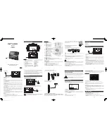
TFTV992
Brand: Coby Pages: 9

ElectroMate VEC097
Brand: Vector Pages: 20

MMA3683n
Brand: Magnavox Pages: 10

MHT825
Brand: Magnavox Pages: 12

POWER 12
Brand: CAMPAGNOLA Pages: 70

AE 6370
Brand: Philips Pages: 2

AE 4230
Brand: Philips Pages: 2

AE 6545
Brand: Philips Pages: 5

AE 6745
Brand: Philips Pages: 10

AE1125
Brand: Philips Pages: 10

AE1500
Brand: Philips Pages: 14

AE 5250
Brand: Philips Pages: 17

AE 5252
Brand: Philips Pages: 27

IC-F3022S
Brand: Icom Pages: 32


