Donaldson Downflo Evolution DFE 2-12, Installation, Operation And Maintenance Manual
The Donaldson Downflo Evolution DFE 2-12 is a powerful dust collector designed for industrial use. For complete guidance on installation, operation, and maintenance, be sure to download the free "Installation, Operation And Maintenance Manual" from manualshive.com. This comprehensive manual will ensure optimal performance and longevity of your equipment.
Share
Download


Reviews:
No comments
Related manuals for Downflo Evolution DFE 2-12
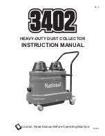
3402
Brand: National Pages: 28

Mini-Gorilla
Brand: Oneida Air Systems Pages: 24

60-101
Brand: Rikon Power Tools Pages: 16

47911
Brand: Central Machinery Pages: 6

MADC20
Brand: FOREDOM Pages: 2

ABS3000
Brand: HOLZMANN MASCHINEN Pages: 34

ABS850DBK
Brand: HOLZMANN MASCHINEN Pages: 35

ABS 1500FF
Brand: HOLZMANN MASCHINEN Pages: 37

10-810
Brand: General International Pages: 10

BT8008
Brand: General International Pages: 40

NOVA FLAIR TAIFUN II Premium GreenTech
Brand: ebm-papst Pages: 12


