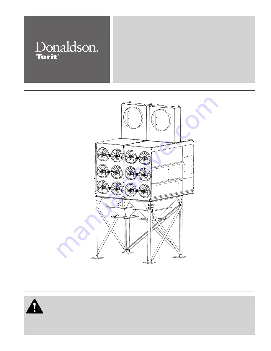
background image

Downflo

®

 Evolution 

DFE 2-8, 2-12, 3-12, 3-18, 3-24, 3-36, 3-48, 3-60, 3-72, 4-16, 4-24, 

4-32, 4-48, 4-64, 4-80, 5-20, 5-30, 5-40, 5-60 and 5-80

Installation and Operation Manual

Installation, Operation, and Service Information

This manual contains specific precautions related to worker safety. The hazard alert image denotes 
safety related instructions and warnings in this manual. DO NOT operate or perform maintenance on this 
collector until you have read and understood the instruction and warnings contained within this manual.

IOM AG8249101 (ENG)

Revision 3

English 

Master Language

Summary of Contents for DFE 2-4

Page 1: ...and Service Information This manual contains specific precautions related to worker safety The hazard alert image denotes safety related instructions and warnings in this manual DO NOT operate or per...

Page 2: ...ipment This manual has been supplied to assist with the installation operation and maintenance for the collector purchased Please read the manual before installing operating or performing maintenance...

Page 3: ...cal Wiring 13 Solid State Timer Installation 15 Solenoid Connection 15 Timer and Solenoid Specifications 15 Preliminary Start Up Check 17 Maintenance Information 18 Operational Checklist 18 Filter Rem...

Page 4: ...owner retains responsibility to comply with applicable codes and standards and to manage the risks associated with the process or materials Donaldson is neither an expert nor a certified consultant in...

Page 5: ...ude metal grinding plasma cutting dry bulk pharmaceutical thermal spray welding metal manufacturing glass and food processing Each application is different and selecting the correct filter for the app...

Page 6: ...id and diaphragm valve aligned to each row of filters provides the pulse cleaning The cleaning sequence starts at the top filter row and continues down through the module Removal inspection or replace...

Page 7: ...e collector will compromise collector performance Inspect collector to ensure all hardware is properly installed and tight prior to operating collector Installation Use proper equipment and adopt all...

Page 8: ...ions to simplify solids collection container handling and routine maintenance and to ensure the straightest inlet and outlet ducts Provide clearance from heat sources and avoid any interference with u...

Page 9: ...in diameter rope type sealant around inlet opening 10 Lift inlet onto collector Secure with bolts washers and nuts supplied Tighten all hardware before removing crane 11 Remove crane 12 Apply sealant...

Page 10: ...All four hopper styles except the screw conveyor hopper provide a 10 inch square discharge opening The screw conveyor hopper provides a single 18 inch discharge opening Use proper equipment and adopt...

Page 11: ...steel anchors Leg and Cross Brace Assembly flat washer hex nut hex nut cross brace leg flat washer hex bolt flat washer hex bolt flat washer leg Typical Foundation Anchor Anchor should project a mini...

Page 12: ...s shown in Detail A 3 Remove outlet cover from the bottom of the clean air plenum and set aside 4 Apply a generous amount of sealant to one module to create an airtight seal between the clean and dirt...

Page 13: ...and tighten hardware starting with the joint between the clean and dirty air plenums Remove excess sealant Detail B Detail C Detail D 3 8 16 x 1 in bolt flat washer sealant module flange module flang...

Page 14: ...tighten hardware at this time 3 Adjust jam nut against the filter cartridge panel Have one person hold the yoke in position as shown in Detail F while another person tightens the three hex nuts from t...

Page 15: ...ail G filter cartridge panel 3 8 in flat washer 3 8 in hex nut venturi 3 8 in hex jam nut 1 2 in gasket washer yoke shoulder 7 16 x 3 4 in thread forming screw sealant detail clean air plenum 3 8 in f...

Page 16: ...tem requirements of 90 100 psig supply pressure The compressed air supply must be oil and moisture free Contamination in the compressed air used to clean filters will result in poor cleaning cleaning...

Page 17: ...ll power before performing installation service or maintenance work Turn compressed air supply OFF bleed and lock out lines before performing service or maintenance work shut off valve safety exhaust...

Page 18: ...ich in turn clean the filters Solenoid enclosures are mounted near or on the collector s compressed air manifold Wire the solenoids to the solid state timer following the wiring diagram supplied with...

Page 19: ...et to clean one or more filters every 10 seconds during a cleaning cycle Do not increase supply pressure above 100 psig as component damage can occur 1FU 2FU 3FU 208 230V 60 Hz 3Ph IL1 IL2 IL3 1M 1OL...

Page 20: ...hat all optional accessories are installed properly and secured 9 Turn power ON at source 10 Turn the compressed air supply ON Set compressed air supply pressure to a level suitable for the filters 90...

Page 21: ...ons and possibly a fault to be corrected For example prolonged lack of compressed air will cause an excess build up of dust on the filters resulting in increased pressure drop Cleaning off line with n...

Page 22: ...below the collector if servicing the dust storage device while the fan is running 1 Empty dust container s drum or bin as necessary to minimize dust in the hopper 2 If the optional 55 gallon drum atta...

Page 23: ...Downflo Evolution DFE 2 8 to 5 80 20 Filter Removal and Installation access cover cover knob yoke filter cartridge alignment marker alignment marker...

Page 24: ...drive VFD is required to control airflow through the collector Lack of a control damper or VFD will shorten filter life Optional Equipment The collector can accept direct mounted fan blowers Torit Bac...

Page 25: ...upport Bracket For complete information see the most current version of the TBI or TRB Fan Installation Operation and Maintenance manual Side and Top Mount Damper and Silencer Support Bracket silencer...

Page 26: ...the cover to the drum if equipped 5 Connect the flexible hose between the drum cover and slide gate Secure with hose clamps Without Slide Gate 1 Place 1 4 in diameter rope type sealant between the hop...

Page 27: ...asher 3 8 16 hex nut flexible hose hose clamp customer supplied 55 gallon drum optional latch hopper flange 1 8 in gasket spacer slide gate drum cover 3 8 16 bolt flat washer lock washer 3 8 16 hex nu...

Page 28: ...e independently supported Rotary Valves are used to maintain a seal on the hopper outlet while material is discharged from the hopper A transition allows a valve to be connected to the hopper discharg...

Page 29: ...two self drilling screws 5 Thirty five feet of plastic tubing is supplied and must be cut in two sections Connect one section of tubing from the gauge s high pressure port to the pressure fitting loc...

Page 30: ...he pressure based switch function provides high pressure ON and low pressure OFF control of the filter cleaning system 1 Choose a convenient accessible location on or near the collector for mounting t...

Page 31: ...or Installation NPT male adapter 1 8 in NPT male adapter Photohelic gauge clean air plenum pressure tap location high pressure port low pressure port plastic tubing 1 8 in NPT male adapter dirty air p...

Page 32: ...ting a pressure drop The Delta P Controller measures the pressure drop and provides a visual display in inches water gauge or metric SI units of daPa Filter Cleaning When the pressure drop across the...

Page 33: ...The Delta P Plus Controller offers three filter cleaning options 1 Differential Pressure Cleaning DFF When the pressure drop across the filters reaches the Controller s High Pressure On setpoint the C...

Page 34: ...standard on Downflo Evolution collectors unless another inlet plenum option has been selected The inlet plenum directs the dirty air stream to the back of the dirty air plenum over the venturi sectio...

Page 35: ...enum Air Management Module Air Management Module The air management module is used in applications involving heavy grain loading large or abrasive particles in the airstream or in applications when a...

Page 36: ...ructions are shipped with the platform Dropping the platform can result in personal injury and or property damage Secure the platform assembly to the crane or forklift with straps or clamps Stationary...

Page 37: ...f the basic kit plus a heat cable to deliver heat to the large pulse valves This kit is customer installed and detailed installation instructions are provided 1 Install the power connection kit on the...

Page 38: ...ng of an explosion must be safely directed outdoors away from areas occupied by personnel to reduce risk of personal injury and or property damage The risk of personal injury and or property damage ca...

Page 39: ...properly Check airflow in duct Adjust damper control until proper airflow is achieved and the blower motor s amp draw is within the manufacturer s rated amps Electrical circuit overload Check that the...

Page 40: ...and input power is present but output voltage to the solenoid is not replace the timer board See Solid State Timer Installation Solid State timer out of adjustment See Solid State Timer and Solid Sta...

Page 41: ...Delta P arrow keys do not work Improper operation Press and hold one of the three setpoint keys to use arrow keys Programming keys disabled Remove the Program Disable jumper from Terminals 3 and 4 on...

Page 42: ...A 1 Donaldson Company Inc Appendix A Clean Change Bag In Bag Out Filter and Liner System...

Page 43: ...latable valve and or 50 ft continuous containment liner for discharge Contact your Donaldson Torit representative for additional information on custom collector options Typical Clean Change Filter and...

Page 44: ...charge the hopper The liner system attaches directly to the collector via the continuous liner collar Liner bands and clamps are used to secure the 50 ft liner Each 50 ft liner provides the equivalent...

Page 45: ...ntain containment The following pre installed items are located in each filter access port to facilitate Bag In Bag Out BIBO replacement of the filter Hinged BIBO Cover provides a safety barrier to co...

Page 46: ...he filter opening 6 Place separate unattached O ring gasket in the first groove furthest from collector of the collar This will give two levels of containment between collar and bag 7 Take open steel...

Page 47: ...bag and cartridge on the end of the shelf 6 Loosely reposition the access cover to the end of the filter yoke Filter Removal and Installation Use proper safety and protective equipment when removing c...

Page 48: ...le ties 13 Securely wrap tape around the cut end of the bag covering a minimum of 3 inches around the bag end 14 Properly dispose of the BIBO bag containing the filter 15 If collector contains two fil...

Page 49: ...posure 22 Slowly and carefully slide the bag and both O ring gaskets towards the front of the collar until the back o ring gasket engages the front collar groove furthest from collector illustrated be...

Page 50: ...gasket adjacent to the back O ring gasket 6 Reinstall the band clamp on the front O ring gasket closest to collector 7 Invert the BIBO bag extension with both hands and pull off the bag stub section a...

Page 51: ...ment mark r at the top of the filter endcap non gasketed end must match with the alignment mark s at the top of the filter access opening If knob fails to thread onto yoke on the opposite side of the...

Page 52: ...llowing procedure if replacement of the breather filter should become necessary 1 Press on the metal trigger to release the breather filter and disconnect the assembly 2 Remove and properly dispose of...

Page 53: ...and the sealing surface 5 Place the bag out bag around collar surrounding port hole Starting from the bottom of the collar roll the bag opening over the edge of the collar With both hands move around...

Page 54: ...5 Position the drum cover carefully on top of the 55 gallon drum 6 Secure the 4 clamps of the drum cover clamp assembly to the drum by tightening the knobs Make sure the clamps engage the top rim of...

Page 55: ...llected Dust _________________________________________________________________________ Dust Properties Kst_______________Pmax______________MIE____________MEC_________________ Accessories______________...

Page 56: ...B 2 Donaldson Company Inc Service Notes Date Service Performed Notes...

Page 57: ...Downflo Evolution DFE 2 8 to 5 80 B 3 Date Service Performed Notes...

Page 58: ...B 4 Donaldson Company Inc Date Service Performed Notes Service Notes...

Page 59: ...the foregoing warranty on services Products manufactured by a third party Third Party Product may constitute contain be contained in incorporated into attached to or packaged together with the goods B...

Page 60: ...rs beyond the control of Donaldson can affect the use and performance of Donaldson products in a particular application including the conditions under which the product is used Since these factors are...

Reviews: