


InstallatIon GuIde
7760 LCD Glass Keypad
Description
The DMP Model 7760 LCD Glass Keypad offers the same functionality and flexible features as standard DMP keypads.
The contemporary glass touch design offers an elegant, sleek look to accent any decor. Each 7760 keypad provides a
32‑character touchscreen backlit display, keyboard with easy‑to‑read lettering, three Panic icons, a multi‑functional AC
Power/Armed LED, and an internal speaker.
Installing the Keypad
The keypad housing is designed to easily install using two #6 screws on a flat surface or optional 778 backplate. The
keypad housing is made up of two parts: a hinged cover and a base which contains the circuit board, glass touchscreen,
and keyboard components. A single 4‑wire harness is used to connect the 7760 to the keypad bus of a DMP control panel.
Figure 2 shows the back of the keypad with the 4‑wire harness connected.
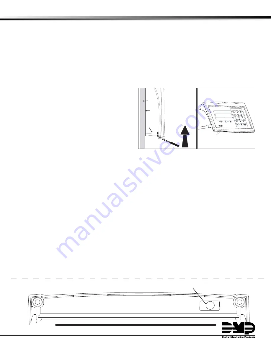
Remove the Cover
Use the following steps and Figures 1 and 2 to remove the
hinged keypad cover.
1. Insert a flat screwdriver into one of the slots on the
bottom of the keypad and gently lift the screwdriver
handle toward you while pulling the halves apart.
Repeat with the other slot.
2. Using your screwdriver, gently separate the left and
right sides of the cover by applying slight inward
pressure along the seam to disengage the internal
side snaps.
3. Gently lift the cover and remove from the four cover
hinges at the top and set aside.
Install the Base
Use the following steps to install the keypad base. Cut off the template below to use for mounting.
1. Place the template on the wall where the keypad is to be mounted and level using the horizontal alignment line.
2. Mark the two #6 screw locations and the wiring harness opening locations on the wall.
3. Install the two supplied #6 wall anchors where marked.
4. Drill a wiring harness hole no larger than 1/4” in diameter where indicated. Feed the 4‑conductor wire through
the created opening.
Note
:
Make sure the wire harness opening is small enough to be covered by the keypad base.
5. Connect the 4‑wire harness to the 4‑conductor Keypad bus wire from the wall.
6. Gently plug the 4‑wire harness connector onto the 4‑pin header through the opening in the back of the keypad.
See Figure 3.
7. Mount the 7760 keypad base to the #6 wall anchors using the provided #6 screws.
Replace the Cover
Use the following steps to reinstall the keypad cover.
1. Gently realign the top four hinges and set the cover into place.
2. Lower the cover and gently snap the two bottom latches and two internal side latches into place by squeezing the
base and cover together to reduce the stress on the legs. (See Figure 3)
Mounting Template
*
*
*
drill 1/4" hole for the Wiring harness
horizontal alignment Line
#6 Screw
Location
#6 Screw
Location
✁
Cut along dotted line and use as a drill template to create mounting and wiring holes.
Figure 1: Loosen bottom
of cover
Legs
glass
Keypad
Front
building
Wall
778
backplate
Lift screwdriver
handle up
toward you to
separate keypad
cover from base.
Figure 2: Loosen side
of cover


