


2015006.1
USER’S MANUAL
Revision: 1
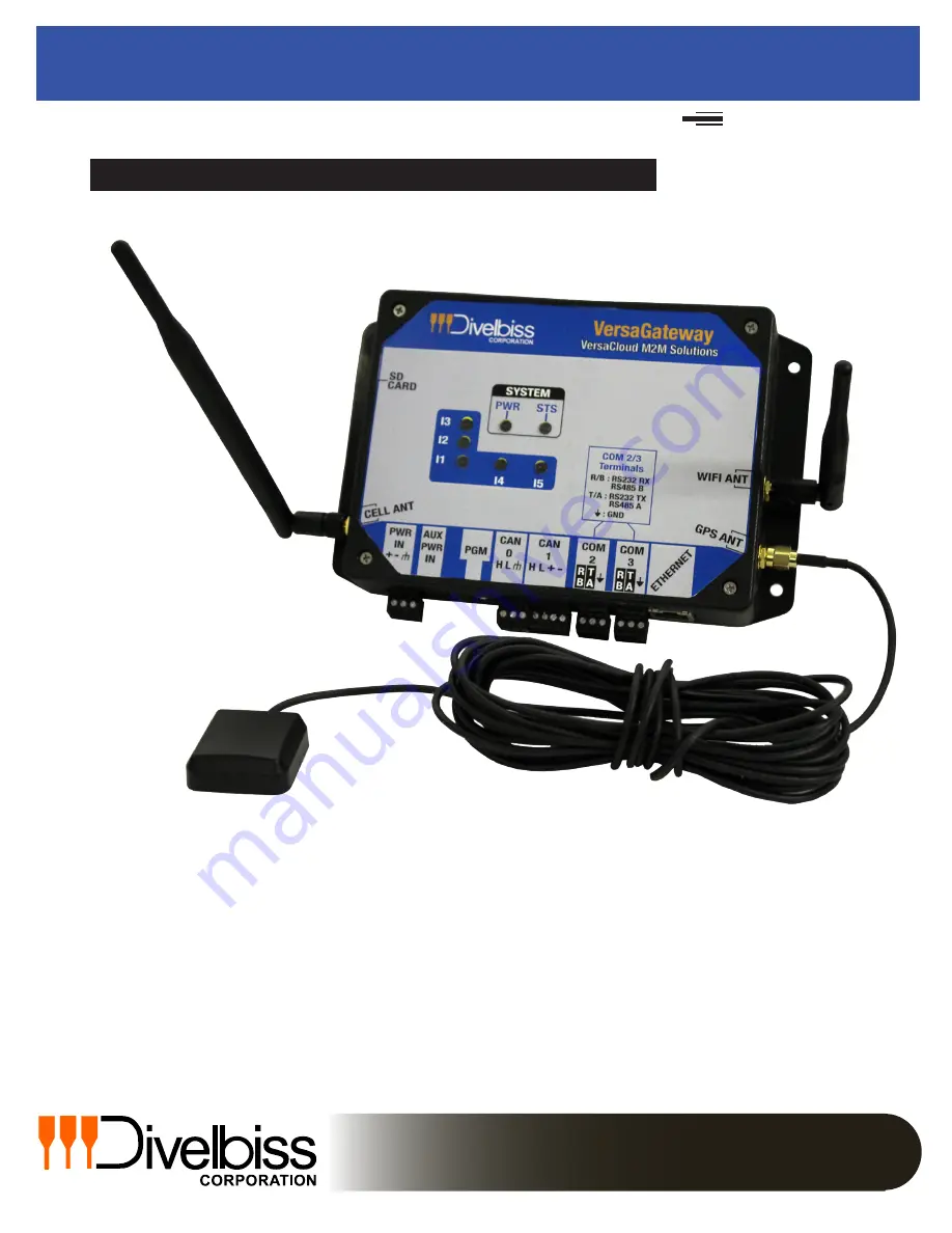
VersaGateway
Covered Models:
VCG-E-C-G
VCG-E-C-X
VCG-E-X-G
VCG-E-X-X
Divelbiss Corporation
9778 Mt. Gilead Road,
Fredericktown, Ohio 43019
Toll Free: 1-800-245-2327
Web: http://www.divelbiss.com
E-mail: [email protected]
Based on P-Series PLC on a Chip
VCG-W-C-G
VCG-W-C-X
VCG-W-X-G
VCG-W-X-X


