background image

PP8 Plus 

       IN50001  Rev. C  04/30/2008 
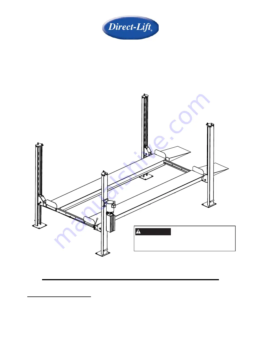


PP8 Plus 

Four Post Lift 

8,000 lbs. Capacity 

(4,000 lbs. per axle)  

Minimum wheelbase 100" at rated capacity 


INSTALLATION / OWNERS MANUAL 


Read this manual thoroughly

 before installing, operating, or maintaining this lift.  When done with 

installation be sure to return documents to package and give all materials to lift owner/operator.  When 

installation is complete be sure to run lift up and down a few cycles with and without “typical” vehicle 

loaded on lift. 

IMPORTANT

Reference ANSI/ALI ALIS,

Safety Requirements for

Installation and Service of Automotive Lifts

before installing lift.

Summary of Contents for PP8 Plus

Page 1: ...talling operating or maintaining this lift When done with installation be sure to return documents to package and give all materials to lift owner operator When installation is complete be sure to run lift up and down a few cycles with and without typical vehicle loaded on lift IMPORTANT Reference ANSI ALI ALIS Safety Requirements for Installation and Service of Automotive Lifts before installing ...

Page 2: ... enough room to install the lock rods You will need at least 9 of clearance from the opposite end of the power unit end of the lift and 6 at the power unit end See floor plan on page 6 The power unit may be installed on the driver s front or the passenger rear corner 7 Never raise a car until you have double checked all bolts nuts and hose fittings 8 Always lower the lift to locks before going und...

Page 3: ...gth 36 3 4 3 3 4 Runway Width 18 1 2 1 6 1 2 Runway Length 165 1 2 13 9 1 2 Runway Height 5 Height of Columns 95 3 4 7 11 3 4 Clearance between Columns 94 7 10 Clearance between Runways 37 3 4 Outside Runway to Outside Runway 74 3 4 6 2 3 4 Clearance Under Runway 81 6 9 Motor specs 110VAC 1HP Shipping Weight 1 733 LBS NOTE WILL NEED AT LEAST 6 FT CLEARANCE TO INSTALL HANDLE ROD NOTE WILL NEED AT L...

Page 4: ...the Cylinder Pulley Now verify that the Main Lifting Cable and both Hex Nuts Item 41 are pre installed and fully tightened to the welded anchor plate and Cable Lock Plate Item 46 4 Locate the four cable ends with Washer and Nyloc Nuts attached Route the appropriate Cable through each hole in corners of the Mainside Runway as shown in Figure 6 Take up as much cable slack as possible and lay each ca...

Page 5: ...p Caps Items 3 4 Figure 1 on the columns 10 Be aware of the offset hole in Top Caps Arrange them so that the cable mounting holes are closest to the runways Use provided bolts nuts washers and lock washers to install Top Caps as shown in Figure 1 11 Secure Top Cap and Lock Ladder assemblies together with Washer and Nut Items 32 92 Position the Crossbeams at the second lowest locking position on al...

Page 6: ... the Nut on the Lock Rod underneath the Top Cap on each post This will lock the Lock Ladder in position 21 Raise lift off all locks until cables are supporting the lift Adjust the Cable Nylon Lock Nut Item 39 located on the top of each post until lift is level on crossbeams and runways This will ensure the lift travels up and down level NOTE YOU MAY NEED TO USE LOCKING PLIERS TO HOLD THE CABLE FRO...

Page 7: ... to caster frames as shown NOTE Hitch Pin and Hairpin Clip will be used to attach casters to lift in following steps DO NOT Install at this time M10 x 1 3 8 Bolt Ø10 Flat Washer Hairpin Clip Hitch Pin Ø10 Flat Washer Ø10 Lock Washer M10 Nut 1 Raise lift 2 3 high 2 Place caster assemblies under crossbeams as shown Secure with Hitchpin and Hairpin Clip 3 Lower lift and the columns will automatically...

Page 8: ...d criteria below FOUNDATION and ANCHORING REQUIREMENTS 1 Concrete shall have compression strength of at least 3 000 PSI and a minimum thickness of 4 in order to achieve a minimum anchor embedment of 3 NOTE When using x 5 long anchors if the top of the anchor exceeds 2 above the floor grade you DO NOT have enough embedment 2 Maintain a 6 minimum distance from any slab edge or seam Hole to hole spac...

Page 9: ...tensions plumb 4 If anchors do not tighten to 85 ft lbs installation torque replace the concrete under each column base with a 4 x 4 x 6 thick 3 000 PSI minimum concrete pad keyed under and flush with the top of existing floor Allow concrete to cure before installing lifts and anchors typically 2 to 3 weeks ...

Page 10: ...ll the hole to depth equal to the length of anchor Note Drilling thru concrete recommended will allow the anchor to be driven thru the bottom of foundation if the threads are damaged or if the lift will need to be relocated 5 For better holding power blow dust from the hole 6 Place a flat washer and hex nut over threaded end of anchor leaving approximately inch of thread exposed carefully tap anch...

Page 11: ...recommended by the manufacturer or ANSI ALI ALOIM 2000 American National Standard for Automotive Lifts Safety Requirements for Operation Inspection and Maintenance Shall display the lift manufacturer s operating instructions ALI SM 93 1 ALI Lifting it Right safety manual ALI ST 90 ALI Safety Tips card ANSI ALI ALOIM 2000 American National Standard for Automotive Lifts Safety Requirements for Opera...

Page 12: ...my device and tag it appropriately as mentioned above 4 Attempt to operate lift to assure the lockout is working Be sure to return any switches to the OFF position 5 The equipment is now locked out and ready for the required maintenance or service Restoring Equipment to Service 1 Assure the work on the lift is complete and the area is clear of tools vehicles and personnel 2 At this point the autho...

Page 13: ...ended attachments 13 ALWAYS WEAR SAFETY GLASSES Everyday eyeglasses only have impact resistant lenses they are not safety glasses SAVE THESE INSTRUCTIONS SAFETY PROCEDURES Never allow unauthorized persons to operate lift Thoroughly train new employees in the use and care of lift Caution the power unit operates at high pressure Remove passengers before raising vehicle Prohibit unauthorized persons ...

Page 14: ...icle on lift runways by having another person guide you onto the runways Check for proper weight distribution center of gravity should be evenly distributed between columns Set vehicle parking brake and chock tires to prevent vehicle movement Use caution before lifting pickup trucks suv s and other vehicles The individual axle weight capacity should not exceed 1 2 of lift capacity Make sure vehicl...

Page 15: ...THE LOCK LEVER TO THE LOCK POSITION IF ANY CORNER STOPS MOVING OR IS SLOWER IN DESCENT ALWAYS LOCK THE LIFT BEFORE GOING UNDER THE VEHICLE NEVER ALLOW ANYONE TO GO UNDER THE LIFT WHEN RAISING OR LOWERING NOTE It is normal for an empty lift to lower slowly it may be necessary to add weight Read and heed all WARNING CAUTION and SAFETY INSTRUCTION labels on lift ...

Page 16: ...nsive property damage lost production time serious personal injury and even death The safety latch system must be checked and working properly before the lift is put to use Failure to heed this warning can result in death or serious injury or damage to equipment If you hear a noise not associated with normal lift operation or if there is any indications of impending lift failure CEASE OPERATION IM...

Page 17: ...and chemical composition of fluid should be considered If operating in dusty environment shorter interval may be required Special Maintenance Tasks NOTE The following items should only be performed by a trained maintenance expert Replacement of hydraulic hoses Replacement of cables and sheaves Replacement or rebuilding air and hydraulic cylinders as required Replacement or rebuilding pumps motors ...

Page 18: ...here should be 1 16 clearance 3 Remove the check valve cover and clean ball and seat WARNING Failure to properly relieve pressure in the following step can cause injury to personnel This lift uses ISO Grade 32 or other good grade non detergent hydraulic oil at a high hydraulic pressure Be familiar with its toxicological properties precautionary measures to take and first aid measures as stated in ...

Page 19: ... not let this overheat power unit Oil Leaks Oil leak causes at the power unit and cylinders are normally caused by the following 1 Power unit if the power unit leaks hydraulic oil around the tank mounting flange check the oil level in the tank The level should be two inches below the flange of the tank A screwdriver can be used as a dipstick 2 Cylinder Piston Rod the rod seal of the cylinder is ou...

Page 20: ...s Cables Columns Runways and other lift parts should be kept free of corrosive agents solvents and road salts If such agents are spilled or splashed on any lift component immediately rinse thoroughly with water and wipe down with a clean rag Spray wire rope cables as required with Penetrating Oil and wipe down Failure to keep lift free of corrosive agents and solvents will lead to reduced componen...

Page 21: ...or bolts for tightness Re torque anchors bolts to 65 ft lbs If anchors do not tighten to the required installation torque replace concrete under each column base per installation instructions Let concrete cure before installing lifts and anchors 4 Columns Look for corrosion giving special attention to the area at the base of the column Check severely corroded areas by pecking with an awl or welder...

Page 22: ...placed as a set every 20 000 cycles estimated or every 6 years unless earlier replacement is indicated during inspection 2 Sheaves and Pins Inspect sheaves and pins in yokes and runways Sheaves are expendable items Sheaves and pins should be replaced when worn Use of sheaves and pins with excessive wear will lead to reduced service life of cables 2 1 Inspect sheaves pulleys in yoke ends with lift ...

Page 23: ...le down to lower lift onto latches Pull on cables under runway to create cable slack c Check for excessive side to side wobble Grasp rim of sheave and attempt to wobble tilt side to side refer to figures above If sheaves wobble tilt more than 1 16 1 6 mm side to side or move in and out more than 1 32 0 8 mm the sheave and sheave pin shaft should be replaced refer to figures above 3 Hydraulic Cylin...

Page 24: ...nspect for worn or missing parts Replace worn or damaged parts as required 2 Observe both locking latches and slack cable devices during lift operation to ensure that all latches line up with slots in latch bar located in all four columns Cable Adjustment 1 Initial Adjustment Adjust cable with lift fully lowered Loosen jam nut and tighten nut on cable stud on top of column until yoke end is raised...

Page 25: ...icle j Raise the lift to full height LISTEN and WATCH as the first locking latch clicks into place Synchronize the other three columns with this column by adjusting their cables so all four latches click at same time Tighten jam nuts When making changes to adjustment nuts on cable end or latch bar stud always leave at least two threads showing between nut and stud end Latches may not click in at t...

Page 26: ...LUSTRATED PARTS LIST 14 25 2 94 A 1 10 1 2 3 4 5 2 7 8 9 17 11 12 13 15 16 4 18 19 20 24 36 10 53 22 37 23 25 26 18 28 28 29 30 92 32 20 22 22 22 23 27 25 23 24 15 23 24 24 33 34 35 25 6 3 96 A 97 98 99 91 100 GENERAL ILLUSTRATED PARTS LIST FIGURE 1 ...

Page 27: ... Plus 27 IN50001 Rev C 04 30 2008 62 62 8987 61 60 59 31 70 67 66 71 18 19 20 72 31 47 57 53 20 56 54 19 20 55 62 38 58 61 60 59 87 89 6 31 64 67 66 65 68 31 62 38 69 63 102 101 CROSSBEAM ASSEMBLY FIGURE 2 ...

Page 28: ...PP8 Plus 28 IN50001 Rev C 04 30 2008 74 91 73 91 38 33 76 76 20 91 75 74 19 74 77 74 38 74 55 75 38 54 90 91 91 RUNWAY COMPONENTS FIGURE 3 33 10 11 12 9 7 37 17 16 HYDRAULIC COMPONENTS FIGURE 4 ...

Page 29: ...PP8 Plus 29 IN50001 Rev C 04 30 2008 86 B 86 64 78 84 84 85 88 83 85 83 85 79 87 87 80 84 93 A 80 A 82 78 81 78 79 30 B 84 83 85 70 78 SAFETY LATCH LINKAGE COMPONENTS FIGURE 5 ...

Page 30: ...PP8 Plus 30 IN50001 Rev C 04 30 2008 50 52 95 9 45 38 38 38 38 39 41 41 41 42 43 51 44 46 47 47 48 49 95 92 CYLINDER CABLE COMPONENTS FIGURE 6 ...

Page 31: ... 1 17 SW 002 30400 9053YZ 90 Degree Fitting 1 18 B30 8 Nut M8 10 19 B40 8 Lock Washer Ø 8 26 20 B41 8 Flat WasherØ 8 62 22 B10 18 100 Hex Head Bolt M18 100 8 23 B41 18 Flat WasherØ 18 8 24 B40 18 Lock Washer Ø 18 8 25 B30 18 Nut M18 8 26 H4D 7001 07 Bolts M8 50 2 27 B10 12 30 Hex Head Bolt M12 30 16 28 B41 12 Flat WasherØ 12 32 29 B40 12 Lock Washer Ø 12 16 30 B30 12 Nut M12 18 31 DP8 2013 Flat Wa...

Page 32: ...M8 10 4 60 DP8 2007 Bushings 4 61 DP8 2006 Cable Pulley Pin 4 62 DP8 2014 Flat WasherØ 24C Level 12 63 NH4D 1011 Spring 8 64 DP8 2011DC Work Lock 2 65 NH4D 1004 Spring 2 66 DP8 2008 Spacer 4 67 DP8 2005 Lock Shaft 4 68 DP8 2010DC Safety Lock 2 69 DP8 2002 Pulley Cover 2 70 DP8 2011 Work Lock 2 71 NH4D 1004DC Spring 2 72 DP8 2010 Safety Lock 2 73 DP8 3007 Plastic Plate 1 74 B23 5 10 Discal Head Scr...

Page 33: ...heel Chock 2 97 H4P R3101 Angle Iron 2 98 H4P R3102 Rubber 8 99 B23 5 16 Discal Head Screw M5 16 8 100 B30 5 Nut M5 8 101 B10 8 40 Hex Head Bolt M8 40 4 102 B33 8 Nylon Lock Nut M8 4 PP8P 7000CK Caster Kit Assembly 4 1 PP8S 2000 Caster Kit Frame Weldment 4 2 B80 6 2A Caster Kit Caster Wheel Assembly 6 2 4 3 PP8S 2100 Caster Kit Hitch Pin 4 4 H4D 5006 03 Caster Kit Hairpin Clip 4 5 B30 10 Hex Nut M...

Page 34: ... adjustments damage or malfunction caused by improper handling installation abuse misuse negligence carelessness of operation or normal wear and tear In addition this warranty does not cover equipment when repairs or alterations have been made or attempted to the Manufacturer s products THIS WARRANTY IS EXCLUSIVE AND IS LIEU OF ALL OTHER WARRANTIES EXPRESSED OR IMPLIED INCLUDING ANY IMPLIED WARRAN...

Reviews: