Digitus Biometrics CodeLock, Руководство по установке
Digitus Biometrics CodeLock - это надежная система безопасности с биометрическим кодом доступа. Проверьте нашу установочную инструкцию для правильной установки и использования устройства. Скачайте бесплатно руководство пользователя с нашего сайта. manualshive.com.
Поделиться
Скачать


Отзывы:
Нет отзывов
Похожие инструкции для CodeLock
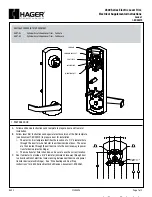
4500 Series
Бренд: hager Страницы: 3

TL100
Бренд: ZKTeco Страницы: 17

Neo RIM N B1 1 Series
Бренд: Salto Страницы: 2

COMPAD
Бренд: Connective Touch Страницы: 24

AR-1203P Series
Бренд: Soyal Страницы: 6

11801
Бренд: LAS Страницы: 4

Real Living Assure Lock YRD226
Бренд: Yale Страницы: 24

SL36E
Бренд: Sylvan Страницы: 13
Saflok Quantum Pixel
Бренд: Dormakaba Страницы: 14

Touch 57
Бренд: Abus Страницы: 9

GKDL-5000Z
Бренд: Z-Wave Страницы: 9

2310
Бренд: Zephyr Страницы: 2

KEYLOCK 2270
Бренд: La Gard Страницы: 2

TL400B
Бренд: Syscom Video Страницы: 14

C8735
Бренд: Stock Loks Страницы: 1

C8724
Бренд: Stock Loks Страницы: 1

Ins-20703
Бренд: Paxton Страницы: 8

ACC518
Бренд: Zap Страницы: 2


