Digi SM-5300 Series, Service Manual
The Digi SM-5300 Series Service Manual is a comprehensive guide designed to assist users in operating and maintaining their Digi SM-5300 product. Download this user-friendly manual for free from our website, ensuring that you have all the necessary information to maximize your product's performance and longevity.
Share
Download


Reviews:
No comments
Related manuals for SM-5300 Series
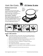
CS Series
Brand: OHAUS Pages: 2

S-100
Brand: Salter Brecknell Pages: 17

Defender D30BR
Brand: OHAUS Pages: 8

MRW series
Brand: Tree Pages: 18

aria
Brand: Fitbit Zip Pages: 26

KH 5502
Brand: Balance Pages: 13

BF-681
Brand: Tanita Pages: 26

BB-300 BF
Brand: Fagor Pages: 64

BK150
Brand: Black & Decker Pages: 12

AMW-150
Brand: AMW Pages: 4

PCS220
Brand: Supco Pages: 9

HDB 5K5
Brand: KERN Pages: 4

FXN-N 10K -3
Brand: KERN Pages: 27

FCE 15K5
Brand: KERN Pages: 13

UOB 1.5T0.5
Brand: KERN Pages: 21

RPB 15K5HM
Brand: KERN Pages: 27

SFB 100K10HIP
Brand: KERN Pages: 43

Detecto 8435
Brand: Cardinal Pages: 12


