

Dialogic
®
IPT10000C IP Board
Quick Install Card
Part Number 64-0082-02
Copyright © 2004-2007
Dialogic Corporation.
All Rights Reserved.
Before You Begin
Protecting the Board from Damage
CAUTION:
All computer boards are sensitive to
electrostatic discharge (“ESD”). Handle all static-
sensitive boards and components at a static-safe work
area, and observe anti-static precautions at all times.
If you are not familiar with ESD safety precautions, visit
http://www.dialogic.com/support/hwinstall
to learn more.
Unpacking the Board
Unpack the Dialogic
®
IPT10000C IP Board (“board”)
according to the following steps:
1.
Prepare a static-safeguarded work area.
2.
Carefully remove the board from the shipping
carton and anti-static packaging. Handle the
board by the edges and avoid touching the
board’s components.
3.
Lay the board on the static-dissipative work
surface.
Note:
Place boards in static-shielding bags when
carrying boards from station to station.
CAUTION
: Do not remove the board from the anti-static
packaging until you are ready to install it. Observe
proper anti-static precautions at all times.
Installing the Hardware
Note:
The hardware must be installed before the system
software.
1.
Turn the power to the chassis
OFF
if you do not have
a live insertion system. If you have live insertion
capability, the power to the chassis can remain
ON
.
2.
Remove the cover plate or open front chassis door.
3.
Select an empty peripheral expansion bus slot.
4.
Use the slot’s board guides as you insert the board
into the chassis slot. Make sure that the tabs on the
board extractors engage the guide holes in the
chassis card cage, then lock down the board
extractors until the red locking tabs snap shut.
CAUTION:
cPCI backplane pins are bent easily. Make
sure that the board is seated with hand pressure before
fully seating board. If the board extractors are used to
seat the board, make sure to seat evenly.
Note:
If the power to the chassis is on, power is
automatically applied to the board, the Out of Service
LED lights briefly and then goes out, and the Power LED
goes on.
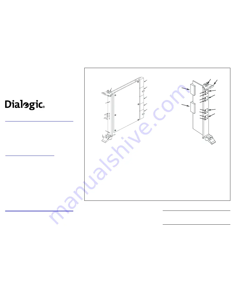
Physical Description
4
2
1
5
OUT OF
SERVICE
POWER
7
8
9
10
CompactPCI
ETHERNET
STATUS
100BT0
100BT1
1000BT0
1000BT1
3
6
11
5
2
2
3
12
12
13
13
15
17
18
19
14
16
1000BT0
100BT0
100BT1
1000BT1
3
20
Main Board
Rear I/O Module
1.
Power LED
2.
Green LED
: Link Established indicator for 100BASE-TX port
3.
Green LED
: Link Established indicator for 1000BASE-T port
4.
Out of Service LED
: Indicates board is out of service or in reset from
the host.
5.
Board Extractor (with red locking tab)
6.
J1
: Connector to Compact PCI backplane
7.
J2
: Connector to Compact PCI backplane
8.
J3
: Connector to Compact PCI backplane
9.
J4
: Connector to Compact PCI backplane
10.
J5
: Connector to Compact PCI backplane
11.
Baseboard retaining screw
12.
Yellow LED:
Activity indicator for 100BASE-TX port
13.
Yellow LED:
Link Not Established indicator for
1000BASE-T port
14.
100BT 0:
Port 0 connector to 100BASE-TX Ethernet
Network
15.
100BT 1:
Port 1 connector to 100BASE-TX Ethernet
Network
16.
1000BT 0:
Port 0 connector to 1000BASE-T
Ethernet Network
17.
1000BT 1:
Port 1 connector to 1000BASE-T
Ethernet Network
18.
J5:
Rear I/O module connector to Compact PCI
backplane
19.
J3:
Rear I/O module connector to Compact PCI
backplane
20.
Rear I/O module retaining screw


