background image

8533-104-001(1/18)

Dexter Commercial OPL Stack Washer Dryer

T-350

Parts & Service Manual

Starting serial number

Summary of Contents for T350

Page 1: ...8533 104 001 1 18 Dexter Commercial OPL Stack Washer Dryer T 350 Parts Service Manual Starting serial number ...

Page 2: ...HE RISK OF DAMAGE OR INJURY refer to accompanying documents follow all steps or procedures as instructed This is the electrical hazard symbol It indicates that there are DANGEROUS HIGH VOLTAGES PRESENT inside the enclosure of this product TO REDUCE THE RISK OF FIRE OR ELECTRIC SHOCK do not attempt to open the enclosure or gain access to areas where you are not instructed to do so REFER SERVICING T...

Page 3: ... on this equipment Prohibited Do not operate without all guards and covers in place Prohibited Do not operate without all guards and covers in place Prohibited Do not wash clothing impregnated with flammable liquids petrochemical Prohibited Do not allow children to play in or around equipment Equipment Safety Warnings Symbols and Terminology Used in this Equipment Part 8533 104 001 1 18 ...

Page 4: ...perty This is the user caution symbol It indicates a condition where damage to the equipment re sulting in injury to the operator could occur if operational procedures are not followed TO REDUCE THE RISK OF DAMAGE OR INJURY refer to accompanying documents follow all steps or procedures as instructed This is the electrical hazard symbol It indicates that there are DANGEROUS HIGH VOLTAGES PRESENT in...

Page 5: ...ined in the installation and op eration instructions unless qualified Do not install washers in an explosive atmosphere Care must be stressed with all foundation work to ensure a stable unit installation eliminating pos sibilities of excessive vibration Foundation must be level within 13 mm to ensure proper washer operation Do not operate washer if door glass is damaged in any way Do not wash clot...

Page 6: ...ensory or mental capabilities or lack of experience and knowledge unless they have been given supervision or instruction concerning use of the appliance by a person responsible for their safety A washer should not be allowed to operate if any of the following occur Excessive high water level Machine is not connected to a properly earthed circuit Door does not remain securely locked during the enti...

Page 7: ...pace Prohibited Do not step or stand on this equip ment Prohibited Do not operate without all guards and covers in place Prohibited Do not operate without all guards and covers in place Prohibited Do not wash clothing impregnated with flammable liquids petrochemical Prohibited Do not allow children to play in or around equipment Part 8533 104 001 1 18 ...

Page 8: ...documentation be fore operating or maintaining equipment Mandatory Disconnect power before servicing equipment Mandatory Lock out and tag out before servicing this equipment Mandatory Disconnect water supply before servic ing equipment Mandatory Children should be supervised to ensure they do not operate equipment Part 8533 104 001 1 18 ...

Page 9: ...g Tips 57 60 Dryer Schematics 60hz 62 63 Section 6 Dryer Parts Data 66 85 Section 7 50hz Gas Dryers 50hz Dryer Parts 88 91 50hz Dryer Schematics 92 93 Section 8 Electric Dryer Parts 208 vac 3ph parts 96 97 240 vac 3ph parts 97 400 vac 3ph 50hz parts 98 Dexter Safety Guidelines FOR SAFETY 1 Always shut off power and water supply and also discharge capacitors before servicing 2 Do not overload the w...

Page 10: ...isplay Push Button 112 Add Bleach LED 113 Power Connection Terminal Block 113 Pressure Switch 114 115 Delta Variable Frequency Drive 116 Delta VFD Motor Leads 116 Delta VFD Dynamic Braking Resistors 116 Delta VFD Cooling Fan 116 Washer Trouble Shooting and F Codes 117 126 Section 9 Washer Electrical Wiring Schematics Start Circuit 128 Fill Circuit 128 129 Wash Circuit 129 Drain Rinse 1 2 Final Rin...

Page 11: ...11 Part 8533 104 001 1 18 Section 1 Washer and Dryer Specifications and Mounting ...

Page 12: ...84EP3X SWKCG USX 9999 711 003 DNS020ED 84EB2X SWKCG USX 9999 709 007 208 60 3 3 wires plus neutral and ground 15kW Heating Elements WNS350XB 12EV3X SWKCS USX 9999 707 001 208 240 60 1or3 Single 2 Wire Ground 3 Phase 3 Wire Ground SN0350ED 85EP3X SWKCG USX 9999 711 004 DNS020ED 85EB2X SWKCG USX 9999 709 009 240 60 3 3 wires plus neutral and ground 15kW Heating Elements N is earthed midpoint of phas...

Page 13: ... DNS020ND 39XB2Z SWKCS VRX 9999 709 014 230 50 1 Single 2 Wire Ground WNS350XB 39XV3Z SWKCS VRX 9999 707 004 230 50 1 Single 2 Wire Ground SN0350ND 17EP3X SWKCS USX 9999 711 008 DNS020ND 15EB2X SWKCS USX 9999 709 002 115 120 208 240 60 1 Single 2 Wire Ground WNS350XB 12EV3X SWKCS USX 9999 707 001 208 240 60 1or3 Single 2 Wire Ground 3 Phase 3 Wire Ground SN0350ND 39AP3X SWKCS VRX 9999 711 009 DNS0...

Page 14: ...cuit Protection Amps 15 amp Electrical Wire Size 12 gauge Electrical Service Single 2 wire ground Electrical Service Three 3 wire ground Water Water Inlet Size 3 4 19mm Flow Rate per min 9 gal 34 1 L Pressure min max 30 120 psi 207 827 Kpa Drain Diameter O D 2 25 5 7 cm Floor to Center of Drain 5 875 14 9 cm Installation Recommendations Clearance Between Machines 1 2 min 1 31 cm Clearance Behind M...

Page 15: ...15 Part 8533 104 001 1 18 ...

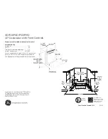
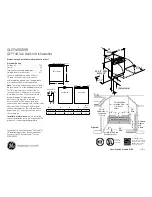
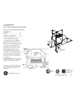
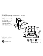
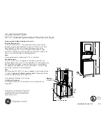
Page 16: ...16 Machine Dimensions Part 8533 104 001 1 18 ...

Page 17: ...17 SWD Mounting Pad Dimensions SWD Mounting Pad Dimensions Part 8533 104 001 1 18 ...

Page 18: ...18 Part 8533 104 001 1 18 Notes ...

Page 19: ...19 Part 8533 104 001 1 18 Section 2 Washer and Dryer Installation Operating Instructions ...

Page 20: ... vibration or movement between the machine and the base or floor Proper Machine Grout Required Installation Machine grout must be installed between base if used and concrete floor on all side rails and crossmem bers If using a base you must grout between base top and machine frame and all side rails and cross members Plumbing Water supply hoses are furnished with each machine The threaded connecti...

Page 21: ...nsformer for the primary incoming power Use the terminal marked 208V for power supplies between 200 and 215 volts Use the terminal marked 230V for power supplies between 216 and 240 volts NOTE Transformer must be set at proper tap for proper operation Electrical Connections Electrical power connections are made to the small terminal block located in the rear of the control trough The terminal bloc...

Page 22: ...t side 0 3 Back 18 Certified for 1 clearance however 18 is required to clean service and maintain the dryer 4 Front 48 to allow use of dryer 5 Top Refer to figure labelled Vertical Clearance Dimensions 6 Floor This unit may be installed upon a combustible floor Makeup Air Adequate makeup air must be supplied to replace air exhausted by dryers on all types of installations Provide a minimum of 100 ...

Page 23: ...ided in the unit gas piping to catch dirt and other foreign articles All pipe connections should be checked for leakage with soap solution Never check with an open flame For altitudes above 2 000 feet 610m it is necessary to derate the BTU input Contact your local distributor for instructions L P gas conversion kits are available for this dryer Contact your local distributor CAUTION The dryer must...

Page 24: ...d on top of the exhaust and must be of such a type as to be free from clogging The type using a cone shaped roof over the pipe is suitable for this application Exhausting the dryer into a chimney or under a building is not permitted In either case there is a danger of lint buildup which can be highly combustible Installation of several dryers where a main discharge duct is necessary will need the ...

Page 25: ...ation B Make the appropriate cycle selection for the wash load by pushing the UP and DOWN arrows on the touch pad Preprogrammed Cycles 1 2 3 4 5 or 6 Each cycle is completely programmable and for instructions see next section in this manual C To manually add wash compounds pour low sudsing powdered detergent into the detergent dispenser on front of the machine Rinse conditioners may also be added ...

Page 26: ... not show this word then press and release the STOP touch pad switch on the dryer controller twice 2 Press and release the UP or DOWN touch pad switch on the dryer controller to select a dry cycle 3 Once the desired dry cycle is selected press and release the START touch pad switch 4 After the dryer controller START touch pad switch is pressed the dryer cylinder will start rotating and the two dig...

Page 27: ...circuit board Jumper Options The jumper located at the lower right side of the circuit board controls whether the controller display shows and operates in the Fahrenheit or Celsius mode This jumper is labeled as TEMP SELECT and has three pins The bottom and middle pins are for Celsius and the top and middle pins are for Fahrenheit which is indicated by the letter C for Celsius and the letter F for...

Page 28: ...28 Part 8533 104 001 1 18 Notes ...

Page 29: ...29 Part 8533 104 001 1 18 Section 3 Washer and Dryer Programming Instructions ...

Page 30: ...d value but for a coinwasher only LO will be put into the cycle Bath Delay Fill dF The selections are d for delay the bath time until water level is reached or t for decrement bath time during the fill Bath Spin Time S 0 to 10 minutes for Prewash Wash Rinse1 and Rinse 2 3 4 1 to 10 minutes for Final Spin Bath IS The owner can change the displayed value but for a coin washer only 0 will be put into...

Page 31: ...e Water Water Delay Spin Injection Time min Temp Level Fill Time min Source Flush 3 CH HI d Prewash 2 CH HI d Wash 7 HH LO d 1 Detergent Rinse 1 1 HH HI d Rinse 2 7 HH LO d 2 Bleach Rinse 3 2 CH HI d 1 Rinse 4 2 CH HI d Final Rinse 4 CH LO d 5 4 Sour Soft Cycle 3 White Towels Hotel Motel Bath Bath Cycle Water Water Delay Spin Injection Time min Temp Level Fill Time min Source Flush Prewash Wash 7 ...

Page 32: ... Delay Spin Injection Time min Temp Level Fill Time min Source Flush 3 CH HI d Prewash 2 CH HI d Wash 2 CH HI d Rinse 1 7 HH LO d 1 Detergent Rinse 2 2 HH HI d Rinse 3 7 HH LO d 2 Bleach Rinse 4 2 CH HI d 1 Final Rinse 2 CH LO d 5 Cycle 6 Colored Cotton Linen Hotel Food Service Bath Bath Cycle Water Water Delay Spin Injection Time min Temp Level Fill Time min Source Flush 2 CH HI d Prewash Wash 10...

Page 33: ... mode 3 Press the DOWN or UP buttons to select which cycle to alter When the desired cycle number is displayed press START 4 The display should now show a b The b and the cycle indicator lights indicate which bath is being selected to alter Press the UP and DOWN buttons to select a bath to change and then press START The indicator lights are shown above When RINSE is selected b r1 through b r4 may...

Page 34: ... cycle and the door lock may remain activated for up to 3 minutes after the cycle has been completed Chemical 120 volt signals will be lost after Rapid advance Mode has been activated until cycle resets To exit the Rapid Advance mode push and hold the STOP button Injection Source Details The washer control may be programmed to send output signals for a chemical injection system There is a separate...

Page 35: ...35 Part 8533 104 001 1 18 Notes ...

Page 36: ...36 Part 8533 104 001 1 18 ...

Page 37: ...g an operating cycle SWITCHES Pushbuttons Description UP INCREASE This touch pad switch will increment increase dry time cool down time and drying temperature It will also scroll upwards when selecting a dry cycle DOWN DECREASE This touch pad switch will decrement decrease dry time cool down time and drying temperature It will also scroll downwards when selecting a dry cycle PROGRAM This touch pad...

Page 38: ...s opened Prog This message is displayed when entering the permanent programming mode 15 This message appears while the dryer is in the heating time of a dry cycle The decimal point will blink if the output for the gas valve is on or remain on constantly if the output for the gas valve is not on The number repre sents the total time left in the dry cycle includes cool down time C02 This message app...

Page 39: ... dryer controller twice 2 Press and release the UP or DOWN touch pad switch on the dryer controller to select a dry cycle 3 Once the desired dry cycle is selected press and release the START touch pad switch After the dryer controller START touch pad switch is pressed the dryer cylinder will start rotating and the two digit total dry cycle time along with a decimal point will appear on the dryer c...

Page 40: ...le pins are for Fahren heit which is indicated by the letter C for Celsius and the letter F for Fahrenheit The other jumper located at the upper right side of the component side of the dryer con troller circuit board is used for choosing either a reversing or non reversing type of dryer This jumper is labeled as REV and NON REV This jumper must be in the non reversing position which are the bottom...

Page 41: ...ontroller can be pressed and re leased to enter the flashing value shown on the 4 digit numeric display and allow you to start the tempo rary dry cycle If you start the temporary dry cycle the 4 digit numerical display will change the total dry time and count down to 0 as the dry cycle progresses PROCEDURE 1 Make sure the dryer is not in a dry cycle The 4 digit numeric display on the dryer control...

Page 42: ... will remain on the cool down L E D will illuminate and the cool down time will be shown on the 4 digit numeric display 8 Press and release either the UP or DOWN touch pad switch on the dryer controller to change the cool down time Once either the UP or DOWN touch pad switch is pressed the temperature L E D and the cool down time on the 4 digit numeric display will flash If you press and hold down...

Page 43: ...ease the SELECT ENTER touch pad switch on the dryer controller The number 45 will stop flashing the dry time L E D will switch off the dryer controller display will now show 180 the temperature L E D will illuminate and the programming L E D and dry cycle 1 L E D will remain on 5 Press and release the UP touch pad switch on the dryer controller one time so the con troller display will show a flash...

Page 44: ...lluminate and the 4 digit numeric display on the dryer controller will change to Prog 4 Press and release either the UP or DOWN touch pad switch to choose the dry cycle you want to change dry cycle 1 through 5 The dry cycle L E D will illuminate to indicate which dry cycle you are choosing If you press and hold down either the UP or DOWN touch pad switch the controller will sequence through the fi...

Page 45: ...e UP or DOWN touch pad switch on the dryer controller to change the cool down time Once either the UP or DOWN touch pad switch is pressed the cool down L E D and the cool down time on the 4 digit numeric display will flash If you press and hold down either the UP or DOWN touch pad switch you will increment UP arrow or decrement DOWN arrow through the cool down times available 2 through 60 minutes ...

Page 46: ...ryer controller will show the number 35 5 Press the UP touch pad switch 18 times until the display of the dryer controller shows the number 53 6 Press and release the SELECT ENTER touch pad switch of the dryer controller once The dry time L E D and programming L E D will remain on the dry time L E D will switch off the temperature L E D will illuminate and the dryer controller display will show th...

Page 47: ...47 Part 8533 104 001 1 18 Section 4 Dryer Service Trouble Shooting ...

Page 48: ... a solid surface NOTE Prewarming the gasket makes the installation much easier 2 Install the window gasket on the clothes door flange The wider lip of the gasket should be on the bottom side or front face of the clothes door and the ridges should be up 3 Locate the seam at the latching stud 4 Apply a soapy water solution or rubber lubricant to the gasket 5 Slide the glass into the middle of the do...

Page 49: ...e regulator cover screw on the gas valve 5 Open the shutoff valve and operate the dryer 6 Adjust the pressure for a manometer reading of 3 5 water column gas pressure 11 0 for L P NOTE The main burners must be operating when adjusting the pressure regulator 7 Shut off the gas supply to the dryer Remove the manometer and install the 1 8 pipe plug in the manifold 8 Open the shut off valve start the ...

Page 50: ...oved to remove the front panels on this model 1 Remove the left two screws with finish washers 2 Remove the right two screws with finish washers at this time the front panel is loose but connected by the harness to the door switch NOTE Always remove power from the machine before changing drive belts or working with the drive system Final Drive Motor Belt Replacement To replace the final drive belt...

Page 51: ...on module is located inside the electrical box This is the metal box on the back of the tumbler area directly to the left of the final drive pulley 2 The red wire from the transformer traveling thru the 1 5 amp fuse and into the module supplies the 24VAC required to operate the entire direct ignition system 3 The black colored hi voltage wire spark plug type plugs onto the post connector on the mo...

Page 52: ...heckout 1 If flame is present during Trial For Ignition period but the system shuts down there may be an improper ground The entire ignition system is grounded together including the electrode assembly the electrode mounting bracket the burners and the burner bracket Shutdown can also occur if for some reason the system isn t sensing the flame Check the sensor for damage and check the connections ...

Page 53: ...he side channels 3 Open the clothes door and insert a 1 4 thick shim at the 3 and 9 o clock positions and a 1 8 thick shim at the 6 o clock position 4 Tighten the two bottom adjusting nuts and tighten locking nuts 5 Tighten the bottom right mounting bolt then the top left mounting bolt Tighten the remaining two bolts Shim where and if necessary 6 Tighten the two top adjusting bolts 7 Remove all th...

Page 54: ...54 Part 8533 104 001 1 18 Notes ...

Page 55: ...55 Section 5 Troubleshooting Wiring Schematics Part 8533 104 001 1 18 ...

Page 56: ... 4 digit display The power to the dryer must be cycled to reset the controller Fault should only occur when starting a dry cycle F4 Gas valve on fault The drying temperature did not increase 1 F in 5 minutes F4 will flash on the display and the dry cycle will finish with out calling for heat energizing gas valve Opening the door or pressing the STOP touch pad switch will reset the fault and clear ...

Page 57: ...or Replace if failed Door switch Check door switch contacts and adjustment Adjust or replace the door switch Electronic Control Is electronic control closing motor relay to power drive motor Check for motor light on electronic control If no light change control If light is on check voltage and wiring to motor Troubleshooting Tips Part 8533 104 001 1 18 ...

Page 58: ...ontrol Check for 24VAC coming into the control on the at burner red wire If voltage then check for 24VAC out on the brown wire Also check for spark at the ignitor If no 24VAC output or no spark to the ignitor replace ignition control Air Flow Switch Check air flow switch to be sure it closes when dryer is running If not adjust or replace switch Hi limit Check for continuity Should be 0 ohms resist...

Page 59: ...cuts to allow no signal back to ignition control Slow drying Temperature Setting Check program for correct high temperature setting Adjust if necessary Air flow restrictions necessary 1 Check lint screen and clean if necessary 2 Check exhaust for correct length and clean if necessary 3 Check exhaust damper to insure that it opens when dryer is running and closes when dryer is not in use 4 Check ma...

Page 60: ...t Accumulation Remove manual overtemp thermostat and inspect in chamber for excessive lint build up Access also gained to this chamber by removing recirculation duct mounted at bottom of chamber or the panel inside burner chamber between burners and rear back panel Exhaust ducting Excessive lint buildup Remove exhaust duct at rear of dryer and inspect for excessive lint build up in complete duct f...

Page 61: ...61 Part 8533 104 001 1 18 Notes ...

Page 62: ...62 Wiring Schematic Dryer Part 8533 104 001 1 18 ...

Page 63: ...63 Wiring Diagram Dryer Part 8533 104 001 1 18 ...

Page 64: ...64 Part 8533 104 001 1 18 Notes ...

Page 65: ...65 Section 6 Dryer Parts Data SWD Part 8533 104 001 1 18 ...

Page 66: ... 9960 314 003 1 6 Plate Assy Hinge SS 9982 393 001 1 Screw Hinge to Door 9545 012 015 4 Nut Hinge to Door 8640 413 002 4 Cover Hinge Plate 9074 377 002 1 Screw Phillips 10B x 3 8 9545 008 010 2 7 Glass Door 9212 002 005 1 8 Gasket Glass Black 9206 413 003 1 Support Door Glass 9548 117 000 1 Tool Install Dryer Door Gasket 8545 064 001 1 9 Gasket Outer Rim Black 9206 420 006 1 10 Handle Loading Door...

Page 67: ...67 8 7 Cabinet Group 1 2 3 4 11 12 13 14 15 17 10 2 3 6 5 9 16 Part 8533 104 001 1 18 ...

Page 68: ...68 Dryer Cabinet Group 24 25 27 21 22 23 20 22 Part 8533 104 001 1 18 ...

Page 69: ...een Assembly ONLY no front 9805 036 002 1 Replaceable Lint Screen Only 9555 057 011 1 24 Lock Door Service Thumb Turn 8650 026 002 1 Cam Lock 9095 044 001 1 Lint Screen Strap Hold Down Screws 10Bx 1 4 9545 008 001 32 25 Controls Assy 24VAC Black 9857 227 001 1 Harness Electronic Control 9627 770 005 1 Control Board 9471 016 001 1 Screw trhdtorx 6bsdx1 2blk 9545 031 009 4 Harness Heat Sensor 9627 6...

Page 70: ...er 9208 132 001 1 6 Warning Label 8502 763 001 1 7 Label Instructions 8502 645 001 1 8 Lighting and Clearance Label 8527 112 001 1 9 Duct Transition 9109 127 001 1 Optional Duct w Cleanout 9973 035 001 1 10 Door Cover Control Box 9108 141 001 1 Cabinet Cover 9074 374 001 1 Insulation 9277 041 028 1 Screw 10AB x 3 8 9545 008 024 10 Wiring Diagram Schematic 9506 821 001 1 1 2 3 4 6 7 9 10 8 5 Part 8...

Page 71: ...01 2 2 Shield Switch 9550 169 003 2 3 Switch Micro 9539 461 009 2 4 Nut Twin 4 40 8640 401 001 2 5 Screw 625 4 40 9545 020 001 2 6 Actuator Air Flow Switch 9008 007 001 2 7 Pin Cotter 09375x 75 9451 169 002 2 8 Screw 10BX x 1 4 9545 008 001 3 Harness Assembly Overtemp Airflow 9627 861 001 1 3 1 2 8 5 6 7 4 Part 8533 104 001 1 18 ...

Page 72: ... 2 x 3 1 2 BLK 8655 073 047 1 11 Control Assy Gas 9857 134 001 1 Wireasy yel 47 8 8220 001 466 1 12 Manifold Assy 9381 012 001 1 Orifice Burner Natural 40 9425 069 030 2 Orifice Burner LP 54 9425 069 031 2 13 Bracket Manifold 9029 306 001 2 14 Pipe Plug in end of Burner Manifold 8615 104 038 1 Screw 10AB x 3 8 9545 008 006 2 15 Bracket High Limit Thermostat 9029 192 001 1 16 Thermostat Hi Limit 95...

Page 73: ...73 1 2 3 4 6 7 9 10 11 12 15 16 18 8 19 13 14 5 17 1 23 Part 8533 104 001 1 18 ...

Page 74: ...Includes bearings Spacer 9803 160 003 1 1 Housing Bearing 9241 161 002 1 Spacer Bearing 9538 139 002 1 2 Bearing Ball Front Rear 9036 130 001 2 3 Screw Wizlock 3 8 24x3 4 9545 049 002 4 4 Nut 5 16 18 8640 400 002 4 5 Screw 3 8 24x1 9545 049 001 2 6 Nut 3 8 24 8640 415 002 2 Part 8533 104 001 1 18 ...

Page 75: ...vinized front 9848 155 002 1 2 Rod Tumbler 9497 019 004 3 3 Washer Special 8641 554 001 3 4 Shim 9552 013 000 AR 5 Spider Assy 9568 018 001 1 6 Nut Wiz Lock 8640 415 004 3 7 Spacer Shaft 9538 164 001 1 8 Tolerance Ring 9487 234 005 1 9 Pulley Driven 9908 052 002 1 10 Washer Flat 1 2 8641 581 026 1 11 LockWasher IntTooth 1 8641 582 016 1 12 Screw 1 2 13x1 1 4 9545 017 009 1 Belt Drive 9040 073 013 ...

Page 76: ...rew 9278 045 001 1 7 Plate Motor Mtg 9982 390 002 1 Bolt 3 8 16 x 3 4 9545 029 008 1 Lockwash Spring 3 8 8641 582 003 1 8 Screw Motor to Plate Screw hxflgwhzlk 5 16 18x5 8 9545 014 004 4 Nut hextwinwhzlk 5 16 18 8640 400 003 4 9 Nut 1 4x20 Motor Plate to Cabinet 8640 414 007 7 10 Clamp cable 3 4 8654 125 004 2 Screw hxhdsltdmach 12abx1 2 9545 048 001 2 11 SupportAssy lntermed Pulley 9991 053 002 1...

Page 77: ...77 Rear View Photos 14 12 2 5 1 6 8 7 11 4 3 13 10 9 Part 8533 104 001 1 18 ...

Page 78: ...1 582 016 1 18 Screw 1 2 13x1 1 4 9545 017 009 1 19 Belt Drive Motor 9040 076 012 1 20 Belt Drive Tumbler 9040 073 013 1 21 Spring Tension 9534 319 002 1 22 Chain Tension 9099 012 011 1 23 Hook Tension 9248 022 002 1 Damper Inside Duct Exhaust 9125 009 001 1 24 Pin Damper Hinge 9451 146 007 1 Box duct lower 9041 113 001 1 Nut Spring 8520 141 000 1 Screw 10B x 1 2 9545 008 026 3 Cover Duct Upper 90...

Page 79: ...79 Rear View Photos 17 14 21 18 27 20 19 15 26 22 20 16 23 24 28 Part 8533 104 001 1 18 ...

Page 80: ...80 Control Assembly Group 1 2 4 10 9 6 7 5 12 11 8 3 13 14 15 Part 8533 104 001 1 18 ...

Page 81: ...8 Relay Motor 30Amp 24VAC 5192 299 002 1 Screw Phillips 8AB x 1 2 9545 045 012 2 9 Terminal Block Power 9897 026 001 1 Screw Phillips 8AB x 1 2 9545 045 012 2 Harness Assembly Low Voltage Upper 9627 867 011 1 10 Ignition Module 9857 182 001 1 Screw 10AB x 3 4 9545 008 018 2 11 Wire Assembly High Voltage 9631 403 009 1 Door Control Box 9108 141 001 1 Screw 10AB x 3 8 9545 008 024 3 12 Harness Main ...

Page 82: ...Y 1 Door Switches 9539 487 001 2 2 Bracket Mounting lint tray switch 9029 297 001 1 3 Conduit Wire 6068 049 001 1 Grommet Wire 1 2 i d 9029 089 001 1 Key Description T 20 SWD QTY 1 Cover Hinge Black 9074 377 002 1 2 Screw TRHDCR 10B x 3 8 Black 9545 008 010 2 Part 8533 104 001 1 18 ...

Page 83: ...801 111 001 1 Wire Assembly Green Yellow 8220 137 001 1 Wire Assembly Green 8220 001 478 1 2 Nut Hex 6 32 8640 411 003 1 3 Nut Hex 6 32 8640 411 001 3 4 PCB Assyembly Controller opl 9471 016 001 1 5 Plastic Spacer 6x1 2 9538 157 016 4 6 Plate Assembly opl ptd 9982 391 002 1 1 4 3 6 5 2 Part 8533 104 001 1 18 ...

Page 84: ...84 Wiring Diagram Part 8533 104 001 1 18 ...

Page 85: ...85 Wiring Schematic Part 8533 104 001 1 18 ...

Page 86: ...86 Part 8533 104 001 1 18 Notes ...

Page 87: ...87 Part 8533 104 001 1 18 Section 7 50 Hz Gas Dryer ...

Page 88: ... 2 Ignition Control 39 Models 9857 182 001 1 Harness Ignition Control 9627 867 011 1 3 Wire Assembly High Voltage 9631 403 009 1 4 Motor 9376 332 001 1 5 Pulley Motor Drive 9453 185 002 1 6 Harness Motor Extension 9627 864 007 1 Wiring Label Schematic Diagram 39 models 9506 823 001 1 Owner s Manual 8514 282 001 1 Lint Drawer Assembly 39 Models 9866 008 005 1 Part 8533 104 001 1 18 ...

Page 89: ...89 Rear View Photos 5 2 4 3 1 3 Part 8533 104 001 1 18 ...

Page 90: ...0 SWD 39 Gas Control Parts 1 2 Key Description Part Number Qty 1 Kit Honeywell VR86 Valve Flange 9732 162 001 1 Orifice Main Burner 43 9425 069 025 2 2 Gas Control Valve 9857 132 004 1 Part 8533 104 001 1 18 ...

Page 91: ... 169 003 1 3 Switch Micro 9539 461 009 1 4 Nut Twin 4 40 8640 401 001 1 5 Screw 625 4 40 9545 020 001 1 6 Actuator Air Flow Switch 9008 007 001 1 7 Pin Cotter 09375x 75 9451 169 002 1 8 Screw 10ABx1 4 9545 008 001 4 Harness Assembly Overtemp Airflow 9627 861 001 1 3 1 2 8 5 6 7 4 Air Flow Switch Assembly Part 8533 104 001 1 18 ...

Page 92: ...92 Wiring Schematic for Dryer 50hz 230V 21CR Part 8533 104 001 1 18 ...

Page 93: ...93 Wiring Diagram for Dryer 50hz 230V Part 8533 104 001 1 18 ...

Page 94: ...94 Part 8533 104 001 1 18 ...

Page 95: ...95 Section 8 Electric Dryer Parts Part 8533 104 001 1 18 ...

Page 96: ...1 19 LABEL EXHAUSTWARNING ENGLISH 9074 293 001 1 20 LABEL EXHAUSTWARNING FRENCH 9074 294 001 1 21 LABEL WARNINGFOR208V 9114 044 001 1 22 LABEL DRYERLINT ENGLISH 9114 045 001 1 23 LABEL DRYERLINT FRENCH 9114 046 001 1 24 LABEL WIRING INDIVIDUALBRANCH 9185 007 001 1 25 MANUAL OPERATORS DNS020E 9208 142 001 1 26 DECAL CLEARANCE 9277 041 014 1 27 NUT HEXKEPS 1 4 20UNC 2B 9295 004 002 3 28 TERMINAL GRO...

Page 97: ...DE CONTROL HEATER 9551 040 001 2 56 SIDE HOUSING HEATER RH 9551 063 001 1 57 SIDE HOUSING HEATER LH 9551 064 001 1 58 STRIP MARKER TERMINAL 9558 029 006 1 59 WIREHARNESS OVERTEMP AIRSWITCH 9627 861 002 1 60 WRAPPER HOUSING HEATER 9636 217 001 1 61 WRAPPER CONTROL 9636 218 001 1 62 CONTROLASSY OPL NONREV ELEC 9857 227 003 1 63 CNTROLASY T20SWD ELEC OPL84 85 9857 232 003 1 64 CONTROLSASSY ELEC HTR 8...

Page 98: ...ARNING ENGLISH 8502 708 001 1 8 LABEL EXHAUSTWARNING FRENCH 8502 708 002 1 9 LABEL WARNINGFOR208V 8502 711 001 1 10 LABEL DRYERLINT ENGLISH 8502 727 001 1 11 LABEL DRYERLINT FRENCH 8502 727 002 1 12 JUMPER FORMED 9295 004 002 1 13 JUMPER STRAIGHT 9295 005 002 2 14 PULLEY MOTOR 60HZ 9453 185 001 1 15 WIRINGLABEL SCHEMATIC DIAGRAM 9506 835 001 1 16 STRIP MARKER TERMINAL 9558 029 006 1 17 CNTROLASY T...

Page 99: ...99 Part 8533 104 001 1 18 Notes ...

Page 100: ...100 Part 8533 104 001 1 18 Notes ...

Page 101: ...1 0 1 Part 8533 104 001 1 18 Section 9 Washer Service and Trouble Shooting ...

Page 102: ...ove Soap Box mounting bracket and Soap Box followed by removing gasket Step 3 Reasemble reverse operation Note Be sure to note position of washers and spacers behind mounting bracket Tub Front Here carrage bolt Spacer Gasket and Soap Dish Here Soap Box mounting bracket Part 8533 104 001 1 18 ...

Page 103: ...lowing the drive spring to open the valve With the valve open all water in the washer will drain out Drain Valve Cleaning Step 1 Loosen the clamp on the tub hose at the drain valve end and remove the hose from the drain valve Step 2 Loosen the drain hose clamp on the back of the drain valve Remove two drain valve mounting racket screws from the frame of the washer Step 3 Disconnect red black wire ...

Page 104: ...r locked for approximately two minutes after a power failure occurs The lock thermoactuator does not delay the door opening at the end of a normal cycle Unlock Thermoactuator To insure that the lock thermoactuator has retracted by the end of the cycle one minute prior to the end of the cycle the unlock thermoactuator is powered with control voltage making it extend and unblock the door locking gea...

Page 105: ...e to unlock The second job is to close the two piggyback lock sensing switches These switches control power to all of the controls If the door unlocks for any reason these two switches will stop the machine When the door handle is 1 4 to 1 2 of an inch from its fully closed position the latching switch should close The two piggyback lock sensing switches should be open when the door is unlocked an...

Page 106: ...tep 5 Check that lock pawl arm swings to cam lobe to lock position Step 6 The lock stacked switches piggyback must be adjusted as door lock solonoid pulls up on door rod and locking pawl is now blocking door cam from turning and is in full up position The stacked swtiches piggyback have a single actuator arm and it must actuate when single actuator roller wheel rolls to flat side of locking pawl Y...

Page 107: ...r pressure can be evaluated by inserting a dollar bill in several positions and tugging on it See Parts Section for kit to increase door sealing pressure Loading Door Removal Step 1 Support door to prevent dropping Step 2 Remove the bottom 2 bolts holding the lower leaf hinge and then remove it The door can now be lifted from the upper post of the hinge assembly Loading Door Hinge Removal Step 1 F...

Page 108: ...anel Name Plate Removal The name plate may be removed by simply peeling it off Re Installation of Name Plate Step 1 Remove any remaining glue from the control panel Step 2 Before removing the paper backing from the name plate check fit to the control panel The program push buttons are the locating guides Step 3 Remove the paper backing from the right side of the name plate position it on the panel...

Page 109: ...se from the bottom of the switch Step 5 Disconnect the door lock wires from all switches and the door lock gear motor The following illustration of their locations should be consulted Step 6 Disconnect pull rod between solenoid and door lock assembly Step 7 Disconnect the wires to the drain valve at the bottom of the machine Step 8 Remove 4 four bolts at outer tub ring and slide complete assembly ...

Page 110: ... Make sure that the tolerance ring is in place inside the pulley Step 2 The shoulder inside the pulley that holds the tolerance ring should face the back of the washer when installed correctly Step 3 Use a stack of flat washers and a longer bolt to press the pulley onto the basket shaft Step 4 Reinstall the retaining bolt lock washer and flat washer The shaft end bolt with washer should be install...

Page 111: ...shaft Before installing the new sealing ring a bead of silicone should be put on the basket shaft see picture After installing the seals lubricate the faces of the seals with silicone grease see picture Removal Step 1 Remove the drive belt as explained in previous instructions Step 2 Remove the tension spring and bracket Step 3 Disconnect the motor wires in the control area at the top of the machi...

Page 112: ...at front of control trough that is powered with 120 VAC primary and two secondary outputs of 24 27 VAC Controls Transformer This transformer is mounted at the back of the control trough and steps a range of 208 to 240 volts down to 120 volts for the controls There are two terminals on the controls transformer for incoming power One terminal tap is marked for 208 volts use this tap for measured vol...

Page 113: ...s polarity sensitive and must be connected correctly Power Connection Terminal Block This terminal block sets at the very back of the control trough Incoming power to the washer should connect here see Electrical under Installation and Operation Section for exact connections Part 8533 104 001 1 18 ...

Page 114: ...hines manufactured before this date can be upgraded with Kit 9732 213 001 The Pressure sensor is adjustable The Factory settings chart will let you know the starting values for each machine and by following the Switch position chart you can adjust the water levels in 1 4 inch increments from that starting value Part 8533 104 001 1 18 ...

Page 115: ...115 Water Level C Part 8533 104 001 1 18 ...

Page 116: ... current reading is not possible a balanced current reading should be present while the motor is running Delta VFD Dynamic Braking Resistors Two 200 Ohm braking resistors are connected in parallel and attached to the drive at terminals B1 and B2 These resistors allow voltage which is generated by the motor when decelerating to be dissipated They will become hot while the motor is slowing down so c...

Page 117: ... at door hinge for proper operation Door Handle Closed Switch Check single door closed switch at left side of door handle to close when handle is vertical Control Breaker Or Fuse Check 1 5 amp T 1200 uses 2 5 amp breaker or fuse for continuity If no continuity replace breaker Main PCB Replace Door does not lock Check Display For Fault Code Does F1 show on the front of display If yes follow tests d...

Page 118: ...s If no con tinuity check pressure switch hose for obstruction If hose okay change pressure switch No cold wa ter to tub in wash Water Valve Coil Check coil continuity at terminals and replace if no continuity Water Inlet Screens Check water inlet screens for blockage and clean if necessary Water Check to insure that water is turned on and operating Blk or White Wire at Controller and Main Relay P...

Page 119: ... Mounting bolts may be loose and need tightening Drive Belt Worn drive belt can cause vibration and noise Loading Note Small loads contribute to out of balance loading and increase vibration Machine does not spin Pressure Switch Check pressure switch for continuity across terminals 21 22 indicating pressure switch has reset to the empty posi tion If no continuity change pressure switch Machine sta...

Page 120: ... off power Try to clear the fault with the Palm Try a soft Reset of the controller with the white button If problem Replace PCB controller F4 Washer controller communication error Check VFD fault code before turning off power Try the data cable first Move around cable and remove any side loading tension from data cable connector ends Check connection P25 24 23 to P15 Turn power back on to the wash...

Page 121: ...ar at the end of the cycle Check VFD fault code before turning off power Check to ensure the drain valve is operating properly slow drain has potential to cause this code Check to ensure the pressure switch tube is clear of any blockage and the pressure switch is operating properly Check the pressure switch harness F10 After a spin the washer tub does not stop within 150 seconds Check VFD fault co...

Page 122: ...lice them together or replace the motor Step 3 Check braking resistors to see if they measure the correct resistance If a resistor does not measure the proper value replace it F15 The variable frequency drive VFD senses that the internal voltage is too high The source of the problem can originate from two different areas Area 1 The input voltage can be too high or there may be a high level of elec...

Page 123: ...washer and test See Note Measure the incoming line voltage F20 Internal drive error Check VFD fault code before turning off power Turn the power off to the washer Wait one minute Turn the power on to the washer If problem reappears contact your Dexter representative F21 Data error on communications between the controller and drive Internal drive error 32 This error also has CEXX errors associated ...

Page 124: ...layed at washer front A fault code F 13 or F 21 will appear on front display if this procedure has not been reset correctly Note Should a power loss occur during cycle and then power returns P U S H will be displayed and customer must push a temperature selection button to continue the cycle Drive Motor Inverter Type Motor Winding Resistance Chart 20lb C Series Stack Washer Resistance Motor Windin...

Page 125: ...oller problem Reset drive CE14 Command message includes unused characters Possible controller problem Reset drive Normal operation of the VFD VFD display shows operating frequency first very quickly then changes to F0 0 at time power is returned This will stay displayed until the VFD receives a command from main control PCB Pushing start button A CE 10 fault will display at drive if improper commu...

Page 126: ...deflection at center Check braking resistors GF Ground Fault to the drive Check VFD fault code before turning off power Check the wiring connections to the drive and motor Check the ground wiring of the drive motor and incoming connection to ensure a proper ground is present Check for damaged motor wires LU Low Voltage to the drive Check VFD fault code before turning off power Turn the power off t...

Page 127: ...1 2 7 Part 8533 104 001 1 18 Section 10 Washer Electrical Wiring Diagrams Schematics ...

Page 128: ... the door and 24VAC will go to the door lock gear motor on the white red wire from the P17 connector of the relay PCB The door lock gear motor engages and pulls up on the door locking rod locking the door and closing the S2 and S3 door locking switches The S2 locking switch is a backup to the S1 latching switch so that once the cycle starts the S1 isn t criti cal The S3 locking switch provides 26 ...

Page 129: ...itch back to an empty level and restores the 5VDC connection through the pressure switch from the red wires to the orange and yellow wires Rinse 1 2 For Rinse 1 2 3 4 the rinse LED will illuminate the drain valve will receive 24VAC and close The basket will fill and tumble the same as the wash bath for the programmed time The rinse water temperatures are programmable and factory default is cold Fi...

Page 130: ...See wiring diagrams for quantities and resistor ohm values The washer will then tumble for 45 seconds to let the clothes shake loose from the basket and then stop End of Cycle and Door Open Circuit Once the machine stopped 3 things occur 1 The enunciator will signal for 3 seconds letting the user know that it is the end of the cycle 2 The Display of the Washer will scroll CYCLE DONE THANK YOU 3 Th...

Page 131: ...131 Part 8533 104 001 1 18 Notes ...

Page 132: ...132 Wiring Schematic for 60hz OPL Washer Part 8533 104 001 1 18 ...

Page 133: ...133 Wiring Diagram for 60hz OPL Washer Part 8533 104 001 1 18 ...

Page 134: ...134 Part 8533 104 001 1 18 Notes ...

Page 135: ...1 3 5 Part 8533 104 001 1 18 Section 11 Washer Parts ...

Page 136: ...ellow Jumper water valve 8220 123 001 1 Harness Power Terminal Block 9627 747 003 1 10 Harness Extention Transformer 9627 826 001 1 12 Harness P5 Pressure Switch 9627 823 001 1 Circuit Breaker 7 AMP 5198 211 002 1 Wiringlabel schematic 9506 822 001 1 Lock Run Program w Harness 8650 027 001 1 Key Description Part Number Qty Hose Water Supply 3 8 I D 9990 027 011 2 Washer Inlet Hose furnished 8641 2...

Page 137: ...137 1 4 6 8 9 10 7 2 3 5 7 12 9 Part 8533 104 001 1 18 ...

Page 138: ...crew 9545 008 026 4 Nut Spring 8640 399 001 4 Hose Overflow to drain 9242 449 002 1 Clamp Hose overflow to drain 8654 117 009 2 9 Hose Overflow Vent Top 9242 463 005 1 Clamp Hose Vent 8654 117 014 1 10 Vacuum Breaker ALL 9610 001 001 1 11 Bracket Vacume Breaker 9029 288 001 1 12 Screw 10B x 1 2 9545 008 026 4 Hose injectorassembly 9242 461 001 1 13 Injector assembly soap 9883 015 001 1 Cap injecto...

Page 139: ...139 1 4 5 6 7 8 11 12 13 14 15 16 10 1 3 2 9 9 Part 8533 104 001 1 18 ...

Page 140: ...140 1 3 4 5 6 7 8 11 12 13 10 Top 14 15 16 17 Part 8533 104 001 1 18 ...

Page 141: ...h Control Black 9035 060 004 1 10 Panel Top Front Painted 9989 590 002 1 Screw Hex 10B x 1 2 9545 008 026 12 Cover Top Rear 9454 939 001 1 Screw Hex 10B x 1 2 9545 008 026 4 11 Lock Run program w harness 8650 027 001 1 12 Soap Dispenser Assembly Complete Does not include lid 9807 087 001 1 Soap Box mounting Gasket 9206 425 001 1 13 Lid Assembly soap box 9987 104 001 1 Lid screws 10 32x1 2 SS 9545 ...

Page 142: ...ating Ring 9487 261 002 1 12 Bolt 1 2 13x1 1 4 Tub end of bearing Housing 9545 017 009 6 12 Nut 1 2 13 8640 417 005 6 Washer 8641 581 034 6 13 Support Arm Assy Bearing Housing 9991 057 001 6 14 Bolt Pulley end of bearing housing 3 8 16x1 1 2 9545 029 003 6 Nut Flange Locking 3 8 8640 415 004 6 15 Pulley Driven 9453 168 005 1 16 Ring Tolerance 9487 234 001 1 17 Washer 1 2 8641 581 026 2 18 Bolt 1 2...

Page 143: ...143 11 7 9 8 10 10 13 12 13 15 14 16 18 19 8 9 11 11 G 8 9 11 2 Part 8533 104 001 1 18 ...

Page 144: ...g Actuating 9534 364 002 1 10 Screw Hx 10 32 x 1 9545 012 020 1 11 Nut Elastic Stop 10 32 8640 413 004 2 12 Spring Return 9534 364 001 2 13 Pin Guide 9451 193 001 1 14 Ring Retaining 9487 200 005 1 15 Washer 8641 581 031 1 16 Switch Latching Sensing 9539 461 008 1 17 Shield Switch 9550 169 003 3 18 Screw 4 40 x 5 8 9545 020 001 2 18 Nut Twin 8640 401 001 1 19 Switch Locking Sensing 9539 461 007 2 ...

Page 145: ... 4 5 Arm Door Lock 9001 063 001 1 6 Thermoactuator Door Lock Relay 24v 9586 001 003 2 7 Spring Extension 9534 350 001 1 8 Motor Gear Assembly 24v 9914 137 014 1 9 Screw Hxwshrhdslsems 6 32 x 3 16 9545 044 003 6 10 Cross Recessed PAn Hd Tapping screw 9545 031 011 4 11 Screw Pnhdcr 10 32 UNFx0 75 9545 012 029 4 Rod Door Lock 9497 225 014 1 Harness Door Lock Drain P17 9627 820 002 1 Screw 10ab x 3 8 ...

Page 146: ...146 9 13 14 10 11 12 15 1 3 2 4 5 6 7 8 5 Part 8533 104 001 1 18 ...

Page 147: ...534 360 002 1 9 Handle Door 9244 091 001 1 10 Pin Door Handle groove 9451 181 005 1 11 Screw Loading Door Mtg 5 16 TF 9545 056 002 3 Shim Loading Door Hinge Thin 9552 037 001 1 12 Door Hinge Assembly Mounts to Tub Front 9955 030 001 1 Screw Hinge Mtg 5 16 18x 3 4 9545 014 009 3 Lockwasher 5 16 Ext tooth 8641 582 009 3 Wiring Harness doorlock safety Switch Assembly 9627 816 002 1 Wire Assembly Door...

Page 148: ...omplete 9914 137 019 1 4 Plate Motor Mtg 9452 538 001 1 5 Screw 8639 994 001 1 6 Spring Drive 9534 340 001 1 7 Screw 9545 054 001 1 8 Screw 9545 054 002 1 9 Seal V Packer 9532 134 001 1 10 Washer 8641 584 001 1 11 Pin Main Drive 9451 196 001 1 Plate spacers needed for replacement motor mtg plate 9538 149 001 1 8 3 4 5 6 7 9 10 11 8 13 1 2 3 4 5 6 7 Part 8533 104 001 1 18 ...

Page 149: ...sys 9379 183 013 2 1 Screen Inlet end of valve 9555 056 001 2 2 Coil Assy 24 V Invensys 9089 017 004 2 3 Diaphragm Invensys EPDM 9118 049 003 2 4 Guide Solenoid Invensys 9211 021 002 2 5 Armature Invensys 9015 008 001 2 6 Spring Armature Invensys 9534 298 001 2 2 2 4 4 6 5 5 3 1 3 6 Part 8533 104 001 1 18 ...

Page 150: ...t 1 2 13 x 1 1 4 Tub Rings to Base Front Rear 9545 017 009 4 7 Nut 1 2 13 Wizlok 8640 417 005 4 8 Hose Overflow 9242 449 002 1 9 Clamp 8654 117 018 2 10 Tube Over Suds 9242 463 005 1 Clamp 8654 117 014 1 11 Hose Tub to Drain Valve 9242 468 001 1 12 Valve Drain 9379 199 002 1 Screw Valve to Bracket 1 4x3 4 9545 030 002 2 13 Hose Drain Valve to Tube 9242 451 002 1 Clamp Hose Drain Valve to Tube Drai...

Page 151: ...151 1 2 4 3 5 6 7 8 9 13 16 12 10 11 15 20 14 12 Part 8533 104 001 1 18 ...

Page 152: ...crew 8B x 1 4 9545 045 001 2 Lockwasher External Tooth 10 8641 582 006 2 Wire Assembly P12 Red 7 9631 381 018 1 4 PCB assembly Relay Main 9473 006 001 1 PCB support 3 8 edge Holding 9548 285 001 10 Wiring Harness Door Lock P15 P4 9627 816 002 1 Wiring Assembly Yel 32 P14 P13 8220 064 023 2 5 Wiring Harness Drain Thermo Door Gear Motor P17 9627 820 002 1 6 Wiring Harness WaterValve P19 9627 795 004...

Page 153: ... Harness Power Terminal To VFD Control Transformer and ground wire 9627 747 003 1 4 VFD Delta drive 208 240 volt 9375 032 014 1 Cable Data Communication 9806 015 002 1 Wiring Assembly Yel 32 8220 064 023 2 5 Braking resistors 200 ohm 9483 004 002 2 Wire Assembly Jumper BLK Breaking Resistors 8220 117 002 2 6 Circuit Breaker 5198 211 002 1 7 Terminal Block Assy Injector 9897 032 002 1 8 Strip termm...

Page 154: ...9538 157 018 5 Nut Elasticstop 6 32 8640 411 002 4 Nut Hexkeps 6 32 8640 411 003 1 2 Harness LEDPCB 9627 797 001 1 3 Harness Doorlock Switches 9627 816 002 1 4 PCB assembly Mode lights 9473 005 001 1 Spacer Plastic 6x9 16 9537 157 018 2 Nut Hexkeps 6 32 8640 411 003 2 6 Door Locking Actuator 24 volts 9892 017 002 1 Hex Nuts mounting gear motor to control 8640 412 005 4 7 Battery 8612 001 001 1 8 A...

Page 155: ...ver controls 9074 267 001 1 2 Label Fusing Installation 8502 619 004 1 3 Label Warning Risk of Injury Black 8502 759 001 1 4 Label Warning Door Opening Black 8502 757 001 1 Booklet Owners operators 8514 283 001 1 5 Label Dispenser Instructions Black 8502 745 001 1 6 Cover Motor Control 9074 268 001 1 1 2 3 4 5 6 7 Part 8533 104 001 1 18 ...

Page 156: ...156 Wiring Schematic for 60hz opl Washer Part 8533 104 001 1 18 ...

Page 157: ...157 Wiring Diagram for 60hz opl Washer Part 8533 104 001 1 18 ...

Page 158: ...158 Part 8533 104 001 1 18 Notes ...

Page 159: ...159 Part 8533 104 001 1 18 Section 12 50 Hz Washer Models Parts in this section used only in these models All other parts are same as standard 60 Hz pages ...

Page 160: ...LABEL WATERMARK 8502 777 001 1 4 INSTRUCT TRANSFORMERCONN 50HZ 8507 449 002 1 5 MANUAL OPERATORS WNS350 50HZ 8514 283 002 1 6 DRIVE DELTAE 350SWD23 180GOPL 9375 032 020 1 7 WIRINGLABEL SCHEMATIC DIAGRAM 9506 824 001 1 8 WIRINGHARNESS POWERTERMINALBLK 9627 747 006 1 9 HOSEASSY INLET BLACK 1 2 9990 027 014 1 Part 8533 104 001 1 18 ...

Page 161: ...161 Part 8533 104 001 1 18 Notes ...

Page 162: ...162 Wiring Schematic for 50hz Washer 39 Part 8533 104 001 1 18 ...

Page 163: ...163 Wiring Diagram for 50hz Washer 39 Part 8533 104 001 1 18 ...

Page 164: ...164 Part 8533 104 001 1 18 Notes ...

Page 165: ...165 Part 8533 104 001 1 18 Section 13 Maintenance Washer and Dryer ...

Page 166: ...ight oil on top and bottom pivots of the clothes door hinge 6 Grease bearings and shaft of intermediate drive pulley Quarterly 1 Check belts for looseness wear or fraying 2 Inspect gasket of door glass for excessive wear 3 Check tightness of all fasteners holding parts to support channel 4 Check tightness of tumbler shaft retaining nut MUST MAINTAIN 150 FOOT LBS 5 Remove lint accumulation from pri...

Page 167: ...s 1 Check the drive belt for wear and proper tension 2 Clean lint and other foreign material from around drive motor 3 Check all water connections for leaks 4 Wipe and clean the inside of the washer and check all electrical components for moisture and dust 5 Remove and clean water inlet hose filters Replace if necessary 6 After any service always replace all panels before reconnecting electrical p...

Page 168: ...168 Part 8533 104 001 1 18 Notes ...

Reviews: