Detex ECL-620, Installation Instructions Manual
The Detex ECL-620 is a high-quality access control device that ensures maximum security for your premises. With its state-of-the-art features and user-friendly interface, this reliable product guarantees smooth operation. To ensure a hassle-free installation experience, visit our website to download the free Installation Instructions Manual in just a few clicks.
Share
Download


Reviews:
No comments
Related manuals for ECL-620
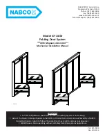
GT-1400
Brand: Nabco Pages: 28

C760
Brand: Waferlock Pages: 21

Smart Keybox v1.0
Brand: Igloohome Pages: 9

Biolock BAC-100
Brand: Camos Pages: 2

Cremone Bolt
Brand: Baldwin Pages: 2

Premis
Brand: Kwikset Pages: 11

808 Reef
Brand: Abus Pages: 2

LAMP HC-30H
Brand: SUGATSUNE Pages: 2

NB IoT
Brand: DigitalKeys Pages: 11

Trilogy ET-PDL Sargent 8812
Brand: Alarm Lock Pages: 2

Sirenlock 710
Brand: Alarm Lock Pages: 2

Trilogy ETPL
Brand: Alarm Lock Pages: 28

3441ZN-GKAG
Brand: Pauli + Sohn Pages: 12

National D8836
Brand: COMPX Pages: 1

SELO-B
Brand: Phoenix Pages: 4

FS1300
Brand: Phoenix Pages: 2

Solar
Brand: Phoenix Pages: 13

LR6600 PS
Brand: ABH Pages: 3


