Denon MC3000, Owner'S Manual
The Motorola MC3000 Operating and Installation Manual is a comprehensive guidebook that provides step-by-step instructions on how to efficiently operate and install the MC3000 product. This invaluable manual is available for free download from manualshive.com, ensuring easy access to all users seeking detailed information and support.
Share
Download


Reviews:
No comments
Related manuals for MC3000

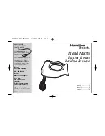
Drink Master
Brand: Hamilton Beach Pages: 5

64650
Brand: Hamilton Beach Pages: 20
62630
Brand: Hamilton Beach Pages: 8

Into the Unknown
Brand: PARASIT STUDIO Pages: 5

MX40
Brand: Avantco Equipment Pages: 16

PT-100 023-9994-000
Brand: Fender Pages: 2

CONVERGE Matrix
Brand: Clear One Pages: 24
APTMIC110AR
Brand: Akura Pages: 10

LPC-48V
Brand: Leprecon Pages: 23

CRAM04
Brand: Clever Acoustics Pages: 12

Pedal I/O 7U Case Adapter
Brand: Intellijel Pages: 13

KSB-200W
Brand: Kemar Pages: 62

116553
Brand: Far Tools Pages: 13

Hummingbird
Brand: EarthQuaker Devices Pages: 2

SM-200
Brand: Doyon Pages: 55

MX410B
Brand: Black & Decker Pages: 2

PERFORMANCE HELIX MX610 Series
Brand: Black & Decker Pages: 2

Perormance Helix MX610B
Brand: Black & Decker Pages: 2


