background image

INSTRUCTION

MANUAL

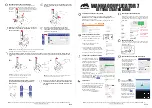
Wood Turning Duplicator

(Model 46-408)

PART NO. 904419 - 02-05-02

Copyright © 2001 Delta Machinery

To learn more about DELTA MACHINERY 
visit our website at: 

www.deltamachinery.com.

For Parts, Service, Warranty or other Assistance,

please call 

1-800-223-7278 (

In Canada call

1-800-463-3582).

Summary of Contents for 46-408

Page 1: ...l 46 408 PART NO 904419 02 05 02 Copyright 2001 Delta Machinery To learn more about DELTA MACHINERY visit our website at www deltamachinery com For Parts Service Warranty or other Assistance please ca...

Page 2: ...tes 2 10 M8 x 40mm Hex Head Screws 2 11 M8 Hex Nuts 2 12 Pattern Support Brackets 2 13 M6 Hex Nut for DL 40 Wood Lathe 2 14 M6 x 30mm Hex Head Screw for DL 40 Wood Lathes 2 15 M8 Hex Nuts for Top Turn...

Page 3: ...hannel on tailstock end of lathe bed NOTE Loosely tighten hardware E 5 Slide the remaining mounting bracket assembly C Fig 6 onto the lathe bed at the headstock end of the wood lathe Move it to about...

Page 4: ...dware F 5 Slide the remaining mounting bracket assembly D Fig 12 at the headstock end of the wood lathe in the same manner NOTE Position the left side of mounting bracket assembly D Fig 12 so it is ap...

Page 5: ...d inside duplicator rail 8 Wrap the loose end of the belt L Fig 19 around the guide on the left side of the rail C and under the lip M of the guide rail Fasten the belt L to the side of the carriage G...

Page 6: ...mounting pad to the other end of duplicator pad in the same manner 4 IMPORTANT To prevent personal injury or damage to the duplica tor use two or more people to mount the duplicator to the mounting br...

Page 7: ...ugh to hold the duplicator rail in place on the mounting brackets 6 Slide duplicator rail C Fig 31 to the left until edge of rail is approximately 1 from right side G of headstock 7 Tighten hardware F...

Page 8: ...removed from handle assembly D in STEP 1 Correct spring tension is determined by the operator and can be adjusted later ATTACHING HANDLES TO CARRIAGE SHAFT 1 Thread four handles J Fig 42 into hub K o...

Page 9: ...iage assembly A and rail Tighten the two corresponding lock screws B 4 Rotate handwheel D Fig 44 and move carriage assembly A back and forth the entire length of the duplicator guide rail E Check for...

Page 10: ...ve cutting tool holder G in or out any further until duplicator is aligned with the lathe 6 Loosen two screws H Fig 50 and slide bracket J to the left until it is flush with the left edge of rail K Ti...

Page 11: ...complete remove leveling screws B and C Fig 53 I Firmly tighten mounting bolts A D Fig 53 Fig 54 Fig 55 Fig 53 FOR MODEL DL 40 16 WOOD LATHES ONLY 10 Loosen four socket head bolts E and F Fig 56 Move...

Page 12: ...carriage assembly N Fig 60 to the headstock until the point of cutting tool P Fig 61 is on the same plane up or down with headstock center O Fig 60 D If the point of cutting tool P Fig 61 is above or...

Page 13: ...utting tool P Fig 65 is above the headstock center O turn leveling screw F Fig 67 counter clockwise until the edge of cutting tool P Fig 65 contacts headstock center O Snug up locknut E Fig 67 F Move...

Page 14: ...plied with the duplicator To adjust the hold ing brackets 1 DISCONNECT MACHINE FROM POWER SOURCE 2 The holding brackets one of which is shown at A Fig 74 can be moved to any area along the duplicator...

Page 15: ...ating operation Tighten two locknuts E after adjustments are made ADJUSTING FOLLOWER ARM The follower arm A Fig 78 rides against either a turning or a template and controls the depth of the cutting to...

Page 16: ...Mount the workpiece between the lathe centers and lock tailstock in position on the lathe bed Adjust the tool advancement arm K Fig 82 so the follower arm G is against the largest diameter of the turn...

Page 17: ...r of the finished piece should be set directly over the center pins of the pattern support brackets D and fastened in position with four screws supplied NOTE After a test cut minor adjustments can eas...

Page 18: ...eturned prepaid to a motor manufacturer s authorized station for inspection and repair or replacement Delta will not be responsible for any asserted defect which has resulted from normal wear misuse a...

Page 19: ...19 NOTES...

Page 20: ...1 Los Angeles 3949A East Guasti Road Phone 909 390 5555 Fax 909 390 5554 San Leandro 94577 Oakland 3039 Teagarden Street Phone 510 357 9762 Fax 510 357 7939 FLORIDA Davie 33314 Miami 4343 South State...

Reviews: