background image

To learn more about 

DELTA MACHINERY

visit our website at: 

www.deltamachinery.com.

For Parts, Service, Warranty or other Assistance,

please call 

1-800-223-7278

 (

In Canada call 

1-800-463-3582

).

Part No. 1238007

Copyright © 2003 Delta Machinery

Dated 11-01-03

I

N

S

TR
U

C

TI

O

N

 MA

N

U

A

L

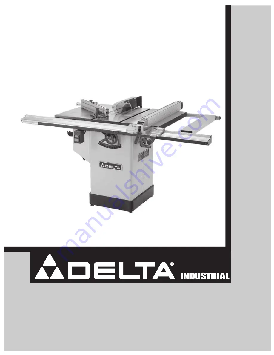
10” Tilting Arbour Saw

(Model 36-655)

Summary of Contents for 36-655

Page 1: ...site at www deltamachinery com For Parts Service Warranty or other Assistance please call 1 800 223 7278 In Canada call 1 800 463 3582 Part No 1238007 Copyright 2003 Delta Machinery Dated 11 01 03 I NSTRUCTION MANUAL 10 Tilting Arbour Saw Model 36 655 ...

Page 2: ...2 GENERAL SAFETY RULES ...

Page 3: ...s dangerous don t try it Figure out an alternative procedure that feels safer REMEMBER Your personal safety is your responsibility This machine was designed for certain applications only Delta Machinery strongly recommends that this machine not be modified and or used for any application other than that for which it was designed If you have any questions relative to a particular application DO NOT...

Page 4: ...ing a workpiece that is twisted or warped or does not have a straight edge to guide along the fence F using featherboards when the anti kickback device cannot be used G never sawing a large workpiece that cannot be controlled H never using the fence as a guide when crosscutting I never sawing a workpiece with loose knots or other flaws 6 ALWAYS USE GUARDS SPLITTER AND ANTI KICKBACK FINGERS except ...

Page 5: ...e switch s is in the OFF position and be sure that the electric current is of the same characteristics as indicated on the machine All line connections should make good contact Running on low voltage will damage the machine POWER CONNECTIONS DO NOT EXPOSE THE MACHINE TO RAIN OR OPERATE THE MACHINE IN DAMP LOCTIONS GROUND INSTRUCTIONS THIS MACHINE MUST BE GROUNDED WHILE IN USE TO PROTECT THE OPERAT...

Page 6: ... to 50 18 AWG 6 10 240 50 100 16 AWG 6 10 240 100 200 14 AWG 6 10 240 200 300 12 AWG 10 12 240 up to 50 16 AWG 10 12 240 50 100 16 AWG 10 12 240 100 200 14 AWG 10 12 240 200 300 12 AWG 12 16 240 up to 50 14 AWG 12 16 240 50 100 12 AWG 12 16 240 GREATER THAN 100 FEET NOT RECOMMENDED MINIMUM GAUGE EXTENSION CORD RECOMMENDED SIZES FOR USE WITH STATIONARY ELECTRIC MACHINES Ampere Rating Volts Total Le...

Page 7: ...Assembly 6 Table Insert with Button Head Screw 1 7 Depth Stop Assembly with Special Washer 1 Socket Head Cap Screw 1 Lock Nut 1 Hex Socket Screws 2 Hex Nuts 2 and Lock Knob 1 8 Cross Cut Fence 9 Blade with Blade Flange 1 and Blade Hex Nut 1 10 Leveling Pads 4 11 Wrench Hook with Self Tapping Pan Head Screws 2 12 Miter Gage Holder with Self Tapping Pan Head Screws 4 13 Fence Holder Brackets 2 with ...

Page 8: ...uts 4 End Caps 2 and Self Tapping Screws 2 4 Rear Rail with Square Head Screws 4 Flat Washers 4 Hex Nuts 4 End Caps 2 and Self Tapping Screws 2 5 Sliding Extension Table with Adjusting Brackets 2 Adjustment Pads 4 Special Washers 4 Self Tapping Screws 4 Hex Head Screws 8 Flat Washers 8 Lock Washers 8 and Hex Nuts 8 Figure 6 1 2 3 4 5 ...

Page 9: ...et Use locking nuts to secure pad position once saw is upright and leveled Figure 8 Place blade tilting handwheel A onto shaft B Make certain slot C in handwheel is engaged with roll pin D on the shaft Thread locking knob E in Fig 9 onto shaft B Figure 9 Assemble the blade raising handwheel A to the front of the saw in same manner Fig 7 Fig 8 Fig 9 Blade Tilting and Raising Handwheels Figure 10 Cu...

Page 10: ...3 locking washers 3 and flat washers are aligned with the three threaded mounting holes B Figure 13 Using the supplied hex head screws lock washers and flat washers A attach the extension wing B to the saw table NOTE Loosely tighten screws until next step is complete Fig 11 Fig 12 Attaching Extension Wings to Saw Table Figure 14 Using a straight edge A check the level of the extension wing B with ...

Page 11: ...l A over square head screws using channel B on back side of rail Extend right side of front rail 17 3 4 past edge of right extension wing then tighten all screws Figure 17 Attach rear rail A in same manner as front rail Extend rear rail 12 1 2 past edge of right extension wing Tighten all screws Fig 15 Fig 16 Figure 18 With sliding extension table A flipped over loosely assemble adjusting brackets...

Page 12: ... tighten all screws Figure 21 Fasten the splitter mounting bracket A to the rear trunion using supplied hex head screws 2 lockwashers 2 and flat washers 2 Do not completely tighten the two screws B at this time Fig 19 Fig 20 Figure 22 Raise the saw arbor to its hightest position Using a straight edge A check to see if the inside splitter bracket B is aligned with the inner arbor flange C Fig 22 Fi...

Page 13: ...rew Figure 25 Fasten the rear of the blade guard and splitter bracket assembly A to the rear splitter mounting bracket B using supplied carriage head screw 1 lockwasher 1 flat washer 1 and hex nut 1 Securely tighten screw assembly C Fig 23 Fig 24 Figure 26 The splitter A has a notch B cut in the top edge This feature will enable the blade guard to stay in the raised position to make blade changing...

Page 14: ...nment is necessary loosen screws C align splitter B with the saw blade and tighten screws C Fig 27 Fig 28 Figure 30 Lower saw blade and install table insert A The table insert should be level with the table surface If an adjustment is necessary see the section Adjusting Table Insert Lock table insert in place using button head screw B NOTE When installing the table insert will automatically releas...

Page 15: ...front rail Figure 37 Move switch A along front rail to a convenient position Tighten the two screws Run the switch to motor cord shortest B up over cabinet top Make connection with motor cord C Fig 35 Fig 36 Figure 38 Attach motor cord A to inside of cabinet using supplied cable clamp hex screw lock washer and flat washer B Fig 38 Fig 37 Installing Switch DISCONNECT TOOL FROM POWER SOURCE ...

Page 16: ...ng pan head screws 4 Figure 40 Attach dust port A to saw cabinet using pan head screws 4 and hex nuts 4 Figure 41 Turn fence body A on its side Attach micro adjusting knob B to fence using button head screws 2 Fig 39 Fig 40 Figure 42 With the fence locking handle A in the raised position lower the rip fence B onto the fence rail C Lock the rip fence by pushing down handle A Fig 42 Fig 41 Dust Port...

Page 17: ...ce B over screws and onto miter gage assembly using channel C on side of fence Tighten screws with fence at desired position Note the assembled depth stop D Figure 45 Attach depth stop assembly A by sliding onto cross cut fence B using channel C on top of fence Lock depth stop using lock knob D Fig 43 Fig 44 Fig 45 Miter Gage DISCONNECT TOOL FROM POWER SOURCE Cross Cut Fence with Depth Stop DISCON...

Page 18: ...crew C with a hex wrench Find 45 degrees then turn set screw clockwise until it bottoms If necessary reset tilt gage Fig 46 Fig 47 Fig 48 Adjusting 90 Degrees and 45 Degrees Positive Stops DISCONNECT TOOL FROM POWER SOURCE Figure 46 To apply power to the saw depress the upper green button on switch A Pressing the lower red button turns the power OFF Starting and Stopping the Saw Raising and Loweri...

Page 19: ...he necessary correction then tighten screws A Figure 51 Once the fence is aligned with the miter gage slot raise the saw blade A to its highest position Slide fence B against blade and lock fence in that position by pushing down on locking handle C Fig 49 Fig 50 Figure 52 The right cursor witness line A should line up with the Zero mark on scale B If it does not loosen screw C and adjust cursor D ...

Page 20: ...ross cutting Loosen lock knob C choose angle and tighten lock knob The miter gage is also equipped with adjustable index stops at 90 degrees D and 45 degrees right and left E Figure 55 Place a straight edge A across the table at both ends of the table insert The table insert B should always be level with the table If an adjustment is necessary turn the four adjusting screws B as needed The table i...

Page 21: ... the box wrench turn arbor nut toward the front of the saw Remove arbor nut blade flange and saw blade Assemble the new blade making sure the teeth point down at the front of the saw table and assemble outside blade flange and arbor nut With open end wrench on the flats of the arbor tighten arbor nut by turning box wrench counterclockwise Replace table insert Fig 56 Fig 57 Use only 10 Diameter Bla...

Page 22: ...22 NOTES ...

Page 23: ...NOTES 23 ...

Page 24: ...arranty is Delta s sole warranty and sets forth the customer s exclusive remedy with respect to defective products all other warranties express or implied whether of merchantability fitness for purpose or otherwise are expressly disclaimed by Delta A complete line of accessories is available from your Delta Supplier Porter Cable Delta Factory Service Centers and Delta Authorized Service Stations P...

Reviews: