Dell EMC Unity 300, Installation Manual
The Dell EMC Unity 300 is a high-performance storage solution designed for small to medium-sized businesses. Ensure smooth installation with the comprehensive Installation Manual available for free download from our website. Get the manual you need to set up your Unity 300 effortlessly at manualshive.com.
Share
Download


Reviews:
No comments
Related manuals for Unity 300

AB2
Brand: M-system Pages: 3
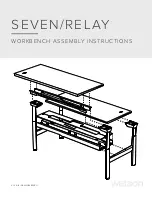
SEVEN
Brand: WATSON Pages: 12

DE2-24
Brand: Oracle Pages: 312

Deskstar 34GXP
Brand: IBM Pages: 2

ST31230N/ND
Brand: Seagate Pages: 36

MSG-U3
Brand: Orico Pages: 27

SAS 760J
Brand: JetStor Pages: 71

AN1003
Brand: Microchip Technology Pages: 33

CANOPIA SKYLIGHT 4x3/1.2x1
Brand: Palram Pages: 50

Insulated Cabin
Brand: DuraMax Pages: 38

DuraMax 53661
Brand: USP Pages: 29

100144403
Brand: Palram Pages: 48

NR-9300
Brand: NEC Pages: 16

USM32A, USM64A, USM128A, USM256A
Brand: Sony Pages: 2

USM1GJ
Brand: Sony Pages: 2

USM16SA3
Brand: Sony Pages: 2

USM16
Brand: Sony Pages: 2

USM128DS
Brand: Sony Pages: 2


