SAS IO Card Cabling
Directly connect the host servers to the storage system.
SAS 4 Port Configuration
1. Connect SAS fault domain 1 (in orange) to server 1.
– Top storage controller: port 1 to port on server 1
– Bottom storage controller: port 1 to port on server 1
2. Connect SASfault domain 2 (in blue) to server 2.
– Top storage controller: port 2 to port on server 2
– Bottom storage controller: port 2 to port on server 2
3. Connect SAS fault domain 3 (in gray) to server 3.
– Top storage controller: port 3 to port on server 3
– Bottom storage controller: port 3 to port on server 3
4. Connect SAS fault domain 4 (in red) to server 4.
– Top storage controller: port 4 to port on server 4
– Bottom storage controller: port 4 to port on server 4
Fault domains provide fault tolerance at the storage controller level. Dell recommends using redundant cabling to avoid a single point of failure.
1. Identify the protocol being used to connect the host servers to the disk array.
2. Refer to the diagram below for cabling guidelines that ensure the configuration has redundancy and failover capability.
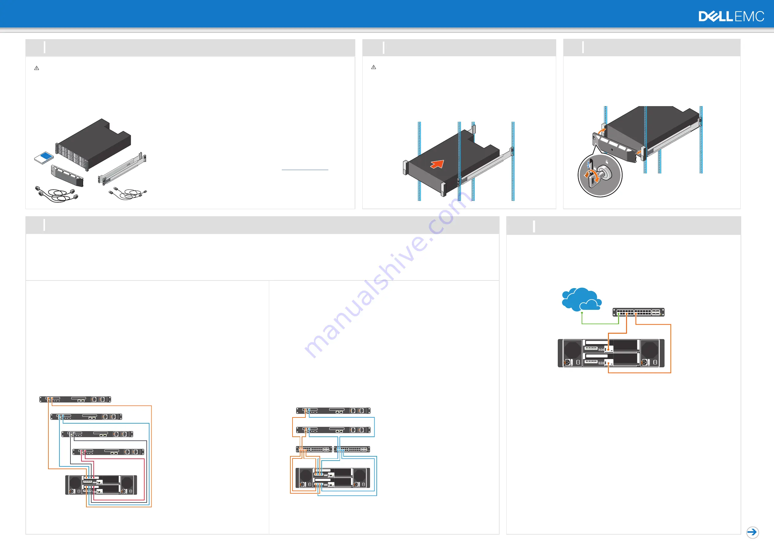
Setting Up Your Dell EMC SCv3000 and SCv3020 Storage System (Front-End SAS)
Warning!
Before you set up and operate your Dell EMC storage system, review the safety
instructions that came with your storage system.
Warning!
The chassis is heavy. Do not attempt to lift
the chassis without assistance.
Use the racking instructions included with your package to mount the chassis.
Mount the storage system chassis and expansion enclosures in a manner that allows
for expansion in the rack and prevents the rack from becoming top-heavy. Secure the
storage system chassis to the rack using the mounting screws that are located behind
the latches on each chassis ear. Dell EMC recommends mounting the storage system
chassis in the bottom of the rack.
1
2
Before You Begin
Mount the Chassis and Optional Enclosures
Unpack Storage Center Equipment
A Dell EMC SCv3000 series storage system includes:
•
Documentation
•
Storage system
•
Front bezel
•
Rack rails
•
Power cables (2)
•
USB cables (2)
Develop a Configuration Plan
Before installing the storage hardware, develop a configuration plan where you can record host
server information, switch information, and network information.
Record System Information
•
System management IPv4 address for Storage Center
•
IPv4 address of the MGMT port on each storage controller
•
Domain name
•
DNS server address
Consider Plans for Multipath/Failover
Redundancy is provided by fault domains, which allow alternate paths if a path fails. Dell EMC
recommends using multipathing, so that volumes are mapped to ports in more than one fault
domain.
More Information
For operating system, host bus adapter (HBA), and switch requirements, refer to the
Dell
Storage Compatibility Matrix
located in the Knowledge Base at
www.dell.com/support.
4
Cable the Host Servers to the Storage System
1. Hold the bezel with the logo upright.
2. Hook the right end of the bezel into the right side of the chassis.
3. Swing the left end of the bezel toward the left side of the chassis.
4. Press the bezel into place until the release latch closes.
5. Use the key to lock the front bezel.
3
Install the Bezel
5
Connect to Management Network
The Ethernet management interface of each storage controller must be connected to a management
network. The Ethernet management port provides access to the Storage Center and is used to send emails,
alerts, SNMP traps, and support data.
1. Connect the Ethernet management port on the top storage controller to the Ethernet switch.
2. Connect the Ethernet management port on bottom storage controller to the Ethernet switch.
iSCSI Mezzanine Card Cabling
If the storage system includes an iSCSI mezzanine card, connect the host servers and storage system to
Ethernet switches.
iSCSI 4 Port Mezzanine Card Configuration
1. Connect each host server to both Ethernet switches.
– Connections shown in orange belong to fault domain 1.
– Connections shown in blue belong to fault domain 2.
2. Connect iSCSI fault domain 1 (in orange) to switch 1.
– Top storage controller: port 1 to switch 1
– Top storage controller: port 3 to switch 1
– Bottom storage controller: port 1 to switch 1
– Bottom storage controller: port 3 to switch 1
3. Connect iSCSI fault domain 2 (in blue) to switch 2.
– Top storage controller: port 2 to switch 2
– Top storage controller: port 4 to switch 2
– Bottom storage controller: port 2 to switch 2
– Bottom storage controller: port 4 to switch 2