dehn VCSD 40 IP65, Instruction For Use & Installation Instructions
Looking for the Instruction For Use & Installation Instructions manual for the dehn VCSD 40 IP65? Look no further! Download the comprehensive manual for free from manualshive.com, ensuring you have all the necessary information to get the most out of this exceptional product.
Share
Download


Reviews:
No comments
Related manuals for VCSD 40 IP65

GEK-45404F
Brand: GE Pages: 32

GEK-106465A
Brand: GE Pages: 43
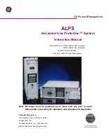
ALPS
Brand: GE Pages: 366

745 TRANSFORMER MANAGEMENT RELAY
Brand: GE Pages: 408

D90 Plus
Brand: GE Pages: 694

AQ-F213
Brand: Arcteq Pages: 455

Pacesetter 2995
Brand: Bodine Pages: 20

CI-50
Brand: Tinker & Rasor Pages: 7

RKPW081915
Brand: StarTech.com Pages: 2

RKPW161915
Brand: StarTech.com Pages: 2

PDU08C13EU
Brand: StarTech.com Pages: 2

PDU08C13AU
Brand: StarTech.com Pages: 2

TB31PCIEX16
Brand: StarTech.com Pages: 14

PDU02IP
Brand: StarTech.com Pages: 24

POW-R BAR RACK USB
Brand: ADJ Pages: 2


