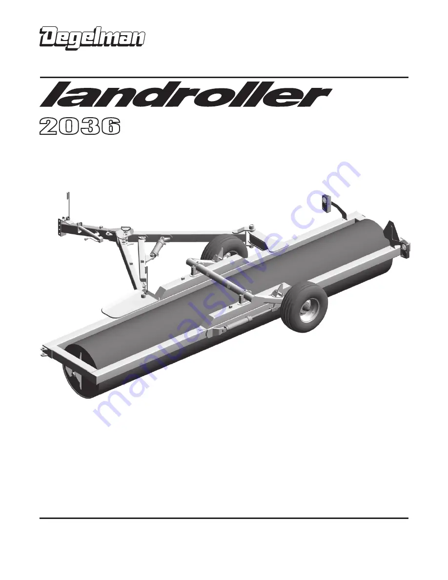
background image

LANDROLLER


SINGLE DRUM

LR2036

OPERATOR & PARTS 

MANUAL

D E G E L M A N   I N D U S T R I E S   L T D.

B O X   8 3 0 - 2 7 2   I N D U S T R I A L   D R I V E ,

R E G I N A ,   S K ,   C A N A D A ,   S 4 P   3 B 1

F A X 306.543.2140 P H 3 0 6 . 5 4 3 . 4 4 4 7

1 . 8 0 0 . 6 6 7 . 3 5 4 5   D E G E L M A N . C O M

143044 v2.2

Summary of Contents for 2036

Page 1: ...TOR PARTS MANUAL D E G E L M A N I N D U S T R I E S L T D B O X 8 3 0 2 7 2 I N D U S T R I A L D R I V E R E G I N A S K C A N A D A S 4 P 3 B 1 FA X 306 543 2140 P H 306 543 4447 1 8 0 0 6 6 7 3 5 4 5 D E G E L M A N C O M 143044 v2 2 ...

Page 2: ......

Page 3: ...TENTS OPERATORS SECTION Introduction 1 Safety 2 Operation 4 Transport to Field Position 7 Field to Transport Position 8 Service Maintenance 9 Maintenance Checklist 11 Repair Hydraulic Cylinder 12 Repair Wheel Hub 15 PARTS SECTION Overview Decal Locations 17 Roller Frame Components 18 Hitch Pole Swing Arm Components 19 Rockshaft Wheel Light Components 20 Hub Spindle Cylinder Components 21 Hydraulic...

Page 4: ......

Page 5: ...g the perfect bed for haying grasses and silage Degelman rollers provide a smooth and level surface for faster easier harvest operations and better seed to soil contact Use this manual as your first source of information about this machine Safe efficient and trouble free operation of your Degelman Landroller requires that you and anyone else who will be operating or maintaining it read and underst...

Page 6: ...autions are not taken WARNING Indicates a potentially hazardous situation that if not avoided COULD result in death or serious injury if proper precautions are not taken CAUTION Indicates a potentially hazardous situation that if not avoided MAY result in minor or moderate injury if proper practices are not taken or serves as a reminder to follow appropriate safety practices Why is SAFETY importan...

Page 7: ...nce procedures and related SAFETY information contained in this manual This manual will take you step by step through your working day and alerts you to all good safety practices that should be adhered to while operating this equipment Remember YOU are the key to safety Good safety practices not only protect you but also the people around you Make these practices a working part of your safety prog...

Page 8: ...nd wait for all moving parts to stop before servicing adjusting repairing or unplugging 3 Keep hands feet hair and clothing away from all moving and or rotating parts 4 Do not allow riders on the Landroller or tractor during operation or transporting 5 Keep all shields and guards in place when operating if applicable 6 Clear the area of all bystanders especially children before starting 7 Do not o...

Page 9: ... the schedule outlined in the Maintenance Section 2 Use only a tractor with adequate power to pull the Landroller under ordinary operating conditions 3 Ensure that the machine is properly attached to the tractor using a drawbar pin with provisions for a mechanical retainer Make sure that a retainer such as a Klik pin is installed NOTE It is important to pin the draw bar in the central location onl...

Page 10: ...n its stowed position 11 When unhooking from the tractor reverse the above procedure HOOK UP UNHOOKING Operation RIDERS 1 Read and understand ALL the information in the Operator s Manual regarding procedures and SAFETY when operating the Landroller in the field yard or on the road 2 Check with local authorities regarding machine transport on public roads Obey all applicable laws and regulations 3 ...

Page 11: ...cylinders to allow removal of the wheel transport bars Move the transport bars into the disengaged position and secure with lock pin 4 Ensure people are clear away from the Landroller area Close retract the Swing Arm cylinder to pivot the roller and frame 90 into field position 5 Position the Transport Pin into field position to secure the hitch pole frame 6 Extend the wheel cylinders raising the ...

Page 12: ...Pin and place it in the holding position 4 Ensure people are clear away from the Landroller area Open extend the Swing Arm cylinder to pivot the roller and frame 90 into transport position 5 Position the Transport Pin into transport position to secure the hitch pole frame 6 Engage the wheel transport bars 2 located near wheels under roller frame You may need to activate retract close the wheel cyl...

Page 13: ...essure before disconnecting or working on hydraulic system MAINTENANCE SAFETY 1 Always place all tractor hydraulic controls in neutral before dismounting 2 Make sure that all components in the hydraulic system are kept in good condition and are clean 3 Replace any worn cut abraded flattened or crimped hoses and metal lines 4 Do not attempt any makeshift repairs to the hydraulic lines fittings or h...

Page 14: ...rdware with the same strength Grade Class bolt IMPERIAL TORQUE SPECIFICATIONS based on Zinc Plated values SAE 5 SAE 8 Size Grade 5 Grade 8 lb ft N m lb ft N m 1 4 7 10 10 14 5 16 15 20 20 28 3 8 25 35 35 50 7 16 40 55 60 80 1 2 65 90 90 120 9 16 90 125 130 175 5 8 130 175 180 245 3 4 230 310 320 435 7 8 365 495 515 700 1 550 745 770 1050 1 1 8 675 915 1095 1485 1 1 4 950 1290 1545 2095 1 3 8 1250 ...

Page 15: ...amaged hoses Check tire pressure 12 5L x15 8 PLY 32 PSI 220 kPa Grease Points 25 Hours Lube points indicated Cast Bearings not roller end bearings Cylinder Pins Joint Pins Grease Points 50 Hours Hubs Spindles Working points pins Safety signs clean Annually Bolt tightness Wheel bearings Plastic wear pad under ramp plate Use the Maintenance Checklist provided for regular service intervals and keep a...

Page 16: ... and remove any kinks or excessive curl to make installation easier and prevent it from falling out b Insert the removal ring into the internal groove with the feathered end pointing into the tube 1 Retract the rod assembly 2 Remove the external steel wire ring REPAIRING A WIRE RING CYLINDER 3 Remove any dirt that may have accumulated on the cylinder head 4 Using the mallet and punch push the head...

Page 17: ... Flush with edge 16 Tap the head the rest of the way until the end is flush with the tube IMPORTANT The head gland must be inserted until it is flush with the tube to allow the inner wire ring to snap into its seated position in the internal cylinder groove Failure to insert the head flush as shown will result in the head and rod assembly coming out of the tube when pressure is applied to the cyli...

Page 18: ...linder end cap 6 Torque cylinder end cap to 440 lb ft 600 N m 7 Tighten Set Screw on end cap to 6 lb ft 8 N m Set Screw Style Barrel Rod Assembly Lock Nut End Cap Locking Ring Piston O Rings Flat Washer Rod Seal Wear Ring Rod Wiper Seal Piston Seals Style may vary 5 Part Seal shown Pin Assembly Shoulder Bolt REPAIRING A THREADED HEAD CYLINDER DISASSEMBLY 1 Loosen Locking Ring and turn off end cap ...

Page 19: ...e careful to install them gently and evenly into hub until they are fully seated 2 Apply a thick wall of grease inside hub Pack grease in cones 3 Install inner cone and dust seal as illustrated 4 Position hub onto spindle and fill surrounding cavity with grease 5 Assemble outer cone washer and nut 6 Tighten nut while rotating hub until there is a slight drag 7 Turn nut back approximately 1 2 turn ...

Page 20: ......

Page 21: ... Amber 2 x 9 1 Safety Decals Keep safety decals and signs clean and legible at all times Replace safety decals and signs that are missing or have become illegible Safety decals or signs are available from your Dealer 142008 Decal Degelman 1 142383 Decal Caution 1 6 Point Safety 1 142422 Decal Danger Stay Clear Crush 1 142557 Decal Reflector Amber 2 x 9 4 142556 Decal Reflector Red 2 x 9 3 142650 D...

Page 22: ...117170 Bearing Insert 2 7 16 1 117168 Bearing Unit 2 2 7 16 4H c w 118028 Bolt 5 8 x 2 1 2 8 117006 Bearing Unit 2 c w 117107 Cast Housing 1 117106 Bearing Insert 1 117022 Lock Ring 1 118026 Bolt 5 8 x 2 8 118508 Lock Washer 5 8 8 118407 Nut 5 8 8 243604 Bushing Roller 2 Mounted with Models prior to S N LR5993 used the following Roller Frame Components Wear Pad Detail Roller Frame Components IMPOR...

Page 23: ... Bolt 5 8 x 2 1 123097 Swing Arm Cylinder Monarch 2 Same as Above 244680 Swing Arm Assembly 1 244690 Cross Arm Assembly 1 133100 Manual Holder 1 243773 Cross Joint Pin 1 118447 Lock Nut 5 8 1 118483 Lock Nut 1 4 unitorque 4 118094 Bolt 5 8 x 4 1 118123 Bolt 1 4 x 1 4 117087 Bushing 1 1 4 x 1 8 x 1 typical 118555 Flat washer 1 4 8 143111 Flexible Hose Holder 1 132030 Jack Sidewind 1 116244 Safety C...

Page 24: ... 10 6 Bolt 1 127006 Valve Stem TR415 1 118651 Jam Nut 9 16 UNF GR2 12 118420 Lock Nut 1 2 2 118422 Lock Nut 3 4 2 118082 Bolt 1 2 x 3 1 2 2 110003 Bearing Base Cast 2 110015 Bearing Cap Cast 2 118509 Lock Washer 3 4 4 118064 Bolt 3 4 x 6 4 611080 Shim 4 131324 Hub Spindle Assembly 2 244659 Transport Bar 2 244640 Rockshaft Assembly 2 118914 Wheel Bolt 9 16 UNF 12 Previously Wheel Hardware Previous ...

Page 25: ...ylinder 118930 Pin 1 x 2 13 16 2 Requires 118796 Shoulder bolt 1 2 GR8 UNC 2 118924 Flat washer 59 ID x 9 OD 2 118930 Pin 1 x 2 13 16 2 Requires 118796 Shoulder bolt 1 2 GR8 UNC 2 118924 Flat washer 59 ID x 9 OD 2 PREVIOUS 122729 Cylinder 3 x 16 x 1 1 2 123085 Seal Kit 123087 Seal Kit PREVIOUS 122730 Cylinder 3 1 2 x 12 x 1 1 2 Hub Spindle Cylinder Components 131701 Hub Cap CTD618 1 118835 Cotter ...

Page 26: ...draulic Fasteners 6 2 3 141527 Tee 3 4 JIC m x JIC m x ORB 2 141515 Connector 3 4 JIC m x ORB 4 141609 Orifice Adaptor 3 4 JIC f x JIC m 1 5 4 141518 90 Elbow 3 4 JIC m x JIC f 2 141504 90 Elbow 3 4 JIC m x ORB 4 1 141581 Quick Coupler m 3 4 ORB 4 126516 Hose 3 8 x 10⁶ 2 249 288 126506 Hose 3 8 x 249 2 126620 Hose 3 8 x 288 2 106 Flexible Hose Holder Stacked Hose Clamps Hose Clamp 780279 Top Plate...

Page 27: ...e Harness w plugs 1 244614 Wire Harness 4 Wire Previous 3 Wire Components w o brake function Wire Harness w plugs 1 244597 Wire Harness 3 Wire 244590 Dual Lamp 3 Wire LH 1 244591 Dual Lamp 3 Wire RH 1 Plug Socket Reference 3 Wire BROWN Socket Plug Tail Lamps WHITE Socket Plug Ground GREEN Socket Plug Right Turn YELLOW Socket Plug Left Turn 7 POLE PLUG viewed from back of plug Ground Tail Running R...

Page 28: ...n screws Red White Black Green Brown White Amber Light Red Light Ground Ground Black Black Black Red White White Green Green White Green Left Wire Right Wire Strip insulation 3 4 then fold wire over before inserting into crimp splice Stagger the crimped connections to prevent bunching up LIGHT CONNECTIONS DETAIL LH RH 246163 Split Loom 3 8 x 24 3 129043 Crimp Splice 16 ga 4 244675 Wire 16 3 Super ...

Page 29: ...ead the Operator s Manual to operate lubricate maintain and store the equipment in accordance with all instructions and safety procedures Failure of the operator to read the operators manual is a misuse of this equipment It is the retail customer and or operators responsibility to inspect the product and to have any part s repaired or replaced when continued operation would cause damage or excessi...

Page 30: ...pplies rental machinery or loss of use No other warranty of any kind whatsoever express or implied is made with respect to this sale and all implied warranties of merchantability and fitness for a particular purpose which exceed the obligations set forth in this written warranty are hereby disclaimed and excluded from this sale This exclusion shall not apply in any jurisdiction where it is not per...

Page 31: ......

Reviews: