


Big Stream 1 Quick Guide
DD4731212
Rev 01
02 December 2020
201 Daktronics Drive
Brookings, SD 57006-5128
www.daktronics.com/support
800.325.8766
Page 1 of 11
This guide explains the setup of a Daktronics “Big Stream 1” system.
This system adds another Digital Media Player (DMP) into an existing
1- or 4-input video control rack. The additional DMP provides an NDI
(Network Device Interface) video output to a compatible customer-
provided streaming device. For more information about setup or
operation of the existing control rack, refer to the documentation
provided with that rack. Refer also to the following YouTube playlist:
https://www.youtube.com/watch?v=vbXFr2aSrnM&list=PL2dNnauPij
Site-specific diagrams may also be available; these will take
precedence over any general instructions found in this guide.
Contact the Daktronics Standard Order Project Manager (SOPM) or
Standard Order Project Coordinator (SOPC) to ask if any site-specific
drawings exist for the project.
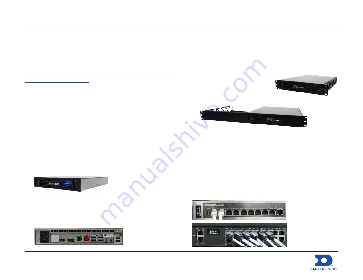
Equipment Setup
Non-Rack-Mount
Follow the instructions below if the new DMP will
not
be mounted into
the existing video control rack (for portability/multi-use facilities).
1.
Unpack all items and verify everything from the Bill of Materials
(BOM) is included.
2.
Locate the DMP unit (part # 0A-1453-7230), and set it in the
desired temporary location (within 25' of the existing control rack).
3.
Connect the DMP power cord into an available outlet on the
rack power strip or nearest wall outlet.
4.
Connect either the 5' (part # W-1506) or 25' (part # W-4638308)
Cat5 network cable between the
left
network jack on the DMP to
an open jack on the network router in the rack.
Rack-Mount
Follow the instructions below if the new DMP is to be mounted into
the existing video control rack.
1.
Unpack all items and verify everything from the Bill of Materials
(BOM) is included.
2.
Locate the DMP unit (part # 0A-1453-7230) and mounting tray.
• 1-input racks require a half-rack
tray (part # EN-2843).
• 4-input racks require a full-rack
tray (part # EN-2842) and a
half-rack filler panel (part # EN-2844).
3.
Mount the DMP unit to the appropriate mounting tray using the
rear thumbscrews. For 4-input racks, also install the half-rack filler
panel into the front-right slot of the tray if desired.
4.
Remove the front filler panel from the existing rack directly below
the existing player(s) and processor(s), and then install the DMP
tray into the open space using the same screws.
5.
Connect the power cord (part # W-1532) between the DMP and
an available outlet on the rack power strip or nearest wall outlet.
6.
Connect the 5' Cat5 network cable (part # W-1506) between
the
left
network jack on the DMP to an open jack on the network
router in the rack.
Note:
An Internet
(WAN) connection
into the network
router in the rack is
required to output
the streaming
video online.


