background image


Dake Corporation 

Phone: 800.937.3253 

www.dakecorp.com


1809 Industrial Park Dr 

Fax: 800.846.3253 

Grand Haven, MI 49417 


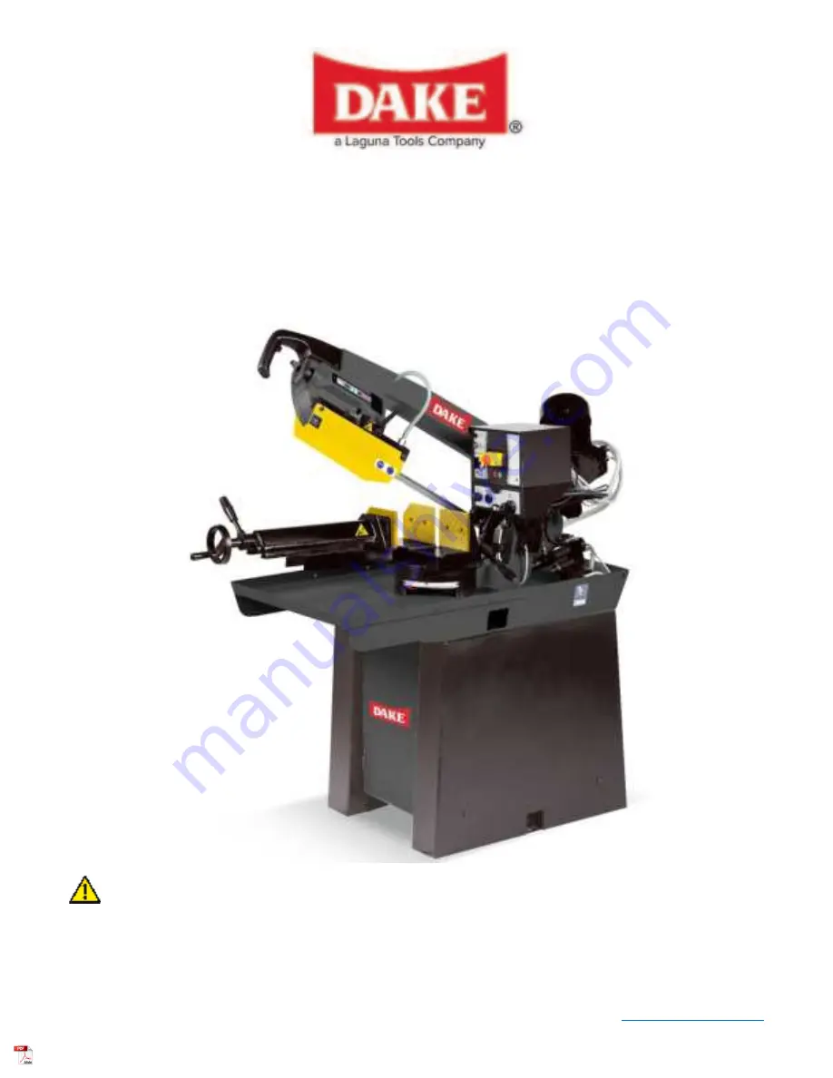
DAKE SEMI-AUTO MITERING BANDSAW 

SE-8.5M 

INSTRUCTIONAL MANUAL 


WARNING!


Read and understand all instructions and responsibilities before operating. Failure to follow 
safety instructions and labels could result in serious injury.  


Summary of Contents for SE-8.5M

Page 1: ... Park Dr Fax 800 846 3253 Grand Haven MI 49417 DAKE SEMI AUTO MITERING BANDSAW SE 8 5M INSTRUCTIONAL MANUAL WARNING Read and understand all instructions and responsibilities before operating Failure to follow safety instructions and labels could result in serious injury ...

Page 2: ...WARNINGS 6 MAIN MACHINE CONTROLS 9 SET UP 10 TRANSPORTATION OF MACHINE 10 ADJUSTMENTS 11 TOOTH SELECTION 11 BLADE SPEED 12 OPERATIONS 13 STARTING SAW 13 USAGE OF RAPID OPENING VISE 13 QUICK HEAD ADJUSTMENT FOR ANGLE CUTS 14 CUTTING SPEED ADJUSTMENT 14 DOWN FEED CONTROLS 15 MAINTENANCE 16 CHANGING BLADE 16 TROUBLESHOOTING 17 ELECTRICAL DIAGRAM 19 EXPLODED VIEWS PART LIST 20 ORDERING INFORMATION 21 ...

Page 3: ... to the repair work completed The standard limited warranty includes repair of the defective component part at no cost to the end user Warranty Process Subject to the conditions hereinafter set forth the manufacturer will repair or replace any portion of the product that proves defective in materials or workmanship The manufacturer retains the sole right and option after inspection to determine wh...

Page 4: ...installation or failure to operate or maintain the unit in accordance with the printed instructions provided c Defects or malfunctions resulting from abuse accident neglect or damage outside of prepaid freight terms d Normal maintenance service or preventative maintenance and the parts used in connection with such service e Units and parts which have been altered or repaired other than by the manu...

Page 5: ...roved by Customer Service a representative will supply a Return Material Authorization RMA number The returned item must have the provided RMA number clearly marked on the outside packaging Any item received without an RMA number clearly visible on the packaging will not be processed An RMA number can only be provided by the Dake Customer Service team and must be obtained prior to the return shipm...

Page 6: ...ies Up to 60 right Lubricant Flood type unit built into the machine electric Controls CE Certified Voltage Available 220 volt for 230 volt machine Horsepower 1 75 AMP 20 amp service for 230 volt machine CUTTING CAPACITIES Degree Round Square Flat 90 8 1 2 7 3 4 10 3 8 x 7 3 4 60 4 1 4 4 1 4 4 1 2 x 4 45 6 3 4 6 3 4 7 3 4 x 6 1 4 In the space provided record the serial number and model number of th...

Page 7: ... your local electrician to install the socket or plug on the power cable end SAFETY RULES FOR ALL TOOLS USER Wear proper apparel No loose clothing gloves rings bracelets or other jewelry to get caught in moving parts Non slip footwear is recommended Wear protective hair covering to contain long hair Always wear eye protection Refer to ANSLZ87 1 standard for appropriate recommendations Also use fac...

Page 8: ...he direction of rotation of the blade Adjust and position the blade guide arm before starting the cut Keep blade guide arm tight A loose blade guide arm will affect sawing accuracy Make sure blade speed is set correctly for material being cut Check for proper blade size and type Stop the machine before putting material in the vise Always have stock firmly clamped in vise before starting the cut Gr...

Page 9: ...ade life always releases blade tension at the end of each workday Check coolant daily Low coolant level can cause foaming and high blade temperatures Dirty or weak coolant can clog pump This can cause low cutting rate and permanent blade failure Dirty coolant can cause the growth of bacteria with ensuring skin irritation When cutting magnesium never use soluble oils or emulsions oil water mix as w...

Page 10: ...Dake Corporation 1809 Industrial Park Dr Grand Haven MI 49417 www dakecorp com 983111 2 9 REV062021 MAIN MACHINE CONTROLS ...

Page 11: ... machine Always keep proper footing and balance while moving this machine Minimum space required for machine operation below INSTALLATION Assemble saw pedestal and bolt saw on the pedestal 1 Tighten all locks before operation 2 Turn off the power before wiring and be sure machine is properly grounded Overload and circuit breakers are recommended for safety wiring 3 Check carefully if the saw blade...

Page 12: ...n You need to consider The width of the cut That is the distance in the cut that each tooth must travel from the point it enters the work piece until it leaves the work piece and the shape of the work piece Use the chart above to assist with tooth selection Squares Rectangles Flats Symbol Locate the width of your work piece on the chart Inches on the outer circle and millimeters on the inner circl...

Page 13: ...mple 4 100mm outside diameter 3 75mm inside diameter tubing 4 100mm OD 12 5 in2 79 cm2 3 75 mm ID 7 0 in2 44 cm2 Area 5 5 in2 35 cm2 5 5 in2 35 cm2 4 100mm distance 1 38 35 mm average width 1 38 35 mm use a 4 6 Vari Tooth BLADE SPEED The band speeds are to be used as a starting point for most application For exact parameters consult your saw blade supplier Material Speed FPM Tool Stainless Alloy S...

Page 14: ...R FORCE Let the weight of the saw head produce the cutting force The saw automatically shuts off at the end of the cut USAGE OF RAPID OPENING VISE The workpiece is places between the vise jaws with the amount to be cut off extending out past the blade Your machine is equipped a handwheel and quick release lever that moves the clamping jaw forward and backwards With material in place run the vise j...

Page 15: ...yond 45 flip up the stop located on the left side attached to the base to allow for greater angle 60 This can also be used to tweak the angles if needed CUTTING SPEED ADJUSTMENT CAUTION Always allow blade to achieve speed before starting your cut and never change speeds while cutting Speed selector switch located on thee control box and has two blade speeds 1 2 1 114 FPM 2 230 FPM It also has a 0 ...

Page 16: ...ter clockwise and slows decent when rotated clockwise Rapid head down Pressing this button allows the head to descend rapidly down to that material Always stop before contacting the material Mode Switch Allows cutting either in the manual or semi automatic mode When cutting in manual mode adjust your cut rate with the head feed speed control That will control the maximum down feed rate you can use...

Page 17: ...If lubrication is insufficient fill it Monthly Check electrical cord plugs switched at least once a month to avoid loosening or wearing CHANGING BLADE Check the compatibility of the NEW blade for the saw Only use a blade with a thickness between 025 and 035 Raise saw head to upper most position and open the blade guards Loosen tension screw knob sufficiently to allow the saw blade to slip off the ...

Page 18: ...is too thick 9 Use a thinner grade 10 Cracking at weld 10 Reweld blade Premature Blade Dulling 1 Teeth too coarse 1 Use finer teeth 2 Blade speeds too fast 2 Reduce speed 3 Inadequate feed pressure 3 Adjust pressure setting 4 Hard spots or scale on material 4 Reduce speed increase feed pressure 5 Work hardening of material 5 Increase feed pressure 6 Blade twist 6 Replace with a new blade and adjus...

Page 19: ...equate blade tension 3 Increase blade tension 4 Dull blade 4 Replace blade 5 Blade speed is incorrect 5 Adjust speed 6 Blade guide assembly loose 6 Tighten 7 Blade tracking too far away from wheels 7 Re track blade Bade Cuts Rough 1 Too much speed or feed 1 Decrease speed or feed 2 Blade is too coarse 2 Replace with finer blade 3 Blade tension loose 3 Adjust blade tension Blade is twisting 1 Cut i...

Page 20: ...ormer S1 2 speed changeover switch S2 Safety guard microswitch S3 Motor start pushbutton S4 Blade tensioner microswitch HL1 Line red HL2 Blade tensioner lamp MI Pump motor M2 Machine motor E V Solenoid valve A M Controlled manual descent commutator FC Case Limit FU1 Fuse 800mA TM Heat protector device of motor PDM Manual descent button EM Emergency stop button B Low voltage coil ...

Page 21: ...23 5 87 08 52 24 UNI 5739 M10x20 25 0 12 07 10 26 UNI 5931 M6x20 27 5 18 19 41 28 5 15 26 39 29 UNI 5588 M10 30 5 18 19 40 31 ISO 7380 M10x16 32 5 18 19 42 33 5 13 38 31 34 UNI 5588 M8 35 UNI 5923 M8x35 36 0 12 07 08 37 5 12 40 33 38 5 14 20 86 39 5 13 38 32 40 Knob hand wheel 303486 41 0 15 26 30 42 5 05 01 38 43 5 19 10 23 44 0 55 14 05 45 5 17 10 70 46 5 15 26 38 47 5 13 38 33 48 UNI 6954 P8x9 ...

Page 22: ... 89 5 12 40 60 90 5 18 28 42 91 0 80 11 01 92 Handwheel 303499 93 0 08 02 60 94 UNI 6592Ø16 95 5 22 20 09 Pos Description Part 96 5 06 60 16 97 0 71 15 28 98 5 12 40 30 99 5 12 20 17 100 UNI 5588M4 101 5 10 05 05 102 5 14 20 58 103 5 08 10 07 104 5 00 15 75 105 5 13 08 71 106 UNI 5933M6x25 107 5 21 42 29 108 0 10 61 20 109 5 12 06 67 110 5 21 40 30 111 0 60 62 09 Pos Description Part 112 5 15 20 7...

Page 23: ...03448 139 1 85 58 07 140 0 24 14 48 141 UNI 7435 Ø8E 142 0 12 33 15 143 5 18 19 43 144 0 14 00 77 145 1 85 58 08 146 0 24 14 47 147 0 88 00 09 148 5 18 17 79 149 Lube group 303422 150 Damper group 303421 151 UNI 5931 M8x40 152 UNI 5931 M8x20 153 UNI 5739 M8x65 154 UNI 5739 M8x30 155 UNI 5588 M14 156 5 17 30 33 157 5 04 00 11 158 UNI 5588 M8 159 Spring 303481 160 5 12 40 80 161 UNI 5739 M12x45 162 ...

Page 24: ... 81 00 11 178 0 81 12 03 179 Transformer 303480 180 5 13 08 65 181 0 60 60 00 182 5 13 79 99 183 5 07 00 02 184 ISO 7380 M4x16 185 0 88 00 07 186 0 88 00 08 187 UNI 5933 M6x15 188 5 13 79 77 189 7 13 25 06 Pos Description Part 190 5 40 23 36 191 0 80 36 17 192 0 82 00 02 193 5 13 79 70 194 UNI 5931 M6x20 195 7 13 05 95 196 UNI 5589 M10 197 5 13 08 67 198 UNI 5931 M10x35 199 5 12 06 69 200 Bearing ...

Reviews: