background image

【INSTRUCTION MANUAL】

DAIKIN  INDUSTRIES,  LTD

.

SE-04430

Hybrid Hydraulic System 


“ECO RICH”


EHU SERIES   

Instruction Manual 


DAIKIN INDUSTRIES, LTD. 


Oil Hydraulics Division


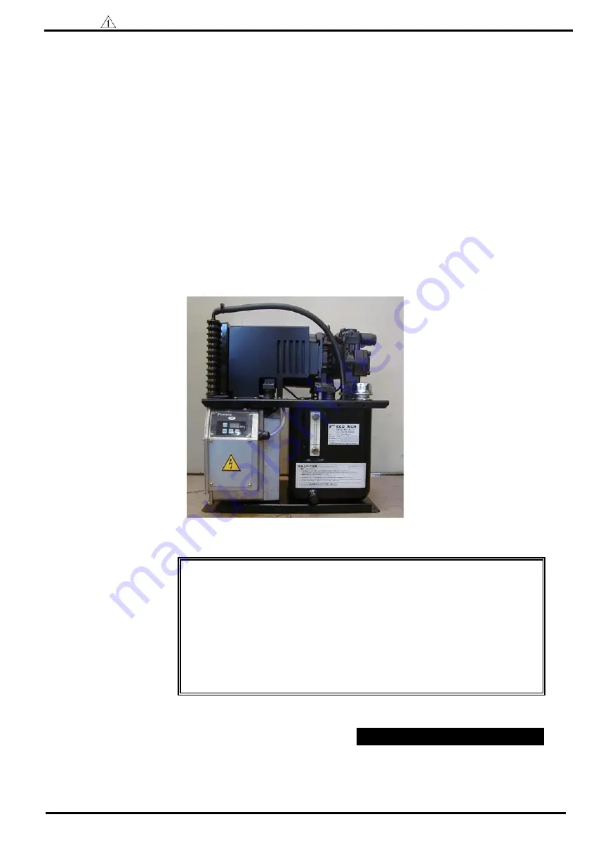
《Photo: EHU25-M07-AE-30》

This instruction manual is based on these following types Eco Rich. 
As for MGF.NO. before them, there is some difference in operating manual of 

the panel  and adjusting method. 


   □

EHU14-L04 -A  -30

MFG.NO.


3C-

**

-

*****

   □

EHU25-L04 -A  -30

MFG.NO.  3C-

**

-

*****

   □

EHU25-L07 -AE -30

MFG.NO.  3D-

**

-

*****

   □

EHU25-M07-AE -30

MFG.NO.  3D-

**

-

*****

   □

EHU30-M07-AE -30

MFG.NO.  3D-

**

-

*****

Summary of Contents for ECO RICH

Page 1: ...ydraulics Division Photo EHU25 M07 AE 30 This instruction manual is based on these following types Eco Rich As for MGF NO before them there is some difference in operating manual of the panel and adjusting method EHU14 L04 A 30 MFG NO 3C EHU25 L04 A 30 MFG NO 3C EHU25 L07 AE 30 MFG NO 3D EHU25 M07 AE 30 MFG NO 3D EHU30 M07 AE 30 MFG NO 3D 1 ...

Page 2: ...e standard for safety operation or maintenance of your machine Symbols of safety precautions in this manual In this manual safety precautions are represented and classify 3 rank Danger Warning and Caution Danger If you ignore this symbol and handle improperly it may pose a high risk of causing death or serious injury Warning If you ignore this symbol and handle improperly it may pose the risk of c...

Page 3: ...uld exempt from any responsibilities Limitation of uses Make sure to consider the situation in case of life threatening owing to breakdown or wrong working of this machine or possibilities of danger to the human body Though this product manufactured under strict quality control in case of using important equipment to prevent serious accident or damage from failure of this machine install safety eq...

Page 4: ...Electric wiring 8 Test run 16 9 Operating manual of the control panel 18 23 General description Explanation of each mode Shift to each mode Operation manual of each mode 10 Maintenance 24 28 Attached document A Change points of the PC setup pressure Att 1 Att 10 1 The PC pressure change point of the standard valve block Fixed setup pressure relief valve 2 The PC pressure change point of the variab...

Page 5: ...ng to the improvement of quality performance and other circumstances 2 Nomenclature 5 a b c d e f g h i MFG NO 30 j k 3 l EHU a Series name EHU EHU Series b Max discharge flow rate of the pump 14 14 L min 25 25 L min 30 28 5 L min c Output characteristics right figure reference L M d Max working pressure 04 4 0MPa the part of Model 5 0MPa 07 7 0MPa e Control method A pressure compensate f Controll...

Page 6: ...able of 20 page b Setup mode and that s column of the initial setup value for a setup of alarm at sipping As for other specifications confirm a delivery specifications form drawings Note 1 Note 2 Note 3 Note 1 Note 2 Note 3 Working condition Hydraulic oil Petroleumseries of specific hydraulic oil anti wear hydraulic oil Refer to our General Sample of Hydraulic Machinery HK196A to see the recommend...

Page 7: ...cations for the non standard products Controller Unit name plate Notice name plate Oil inlet port with air breather Tank Sample port with drain cap Oil gauge Valve block Front view of the unit SR motor and pump Drain port DR 1 Rp 1 Top view of the unit Drain port DR 2 Rp 1 2 Return port T1 Rc 1 2 Return port T2 Rc 1 2 Discharge port p Rc 3 8 Oil cooler Eye bolt ...

Page 8: ...ANUAL DAIKIN INDUSTRIES LTD SE 04430 8 Parts 5 Hydraulic circuit Hydraulic circuit Part NO Name 1 Tank 2 Suction filter 3 Oil gauge 4 Inverter driving pump 5 Oil inlet port with air breather 6 Oil cooler 7 Controller ...

Page 9: ...lt In this time move the unit carefully about balance so as not to be damaged the piping by the hook Eyebolt Detail of spacer 2 places Type Weight EHU14 L04 EHU25 L04 EHU25 L07 EHU25 M07 EHU30 M07 43kg 45kg 46kg Weight table hydraulic oil in not included 9 Danger If the vibration absorbing rubber is suspended without spacer for its protection it is dangerous that the vibration absorbing rubber may...

Page 10: ...ase of touching high temperature part you may be burnt Caution When it is used in where there is no space of inhalation exhaust and heat place the motor becomes high temperature and the life of the motor will be shortened apparently When the motor becomes high temperature temperature protection suspends its operation In case P02 temperature alarm output setting is 1 as output alarm signal are outp...

Page 11: ... the float of the oil gauge is between the red line and the yellow line Use the hydraulic oil appropriate to the specifications as it was mentioned in page 6 Drain port DR1 Rp1 Upper oil surface Discharge port P Rc3 8 Drain port DR2 Rp1 2 Upper oil surface Return port T1 Rc1 2 under oil surface Return port T2 Rc1 2 under oil surface 11 Caution If it operates without putting oil in the tank burnt a...

Page 12: ...er the third class Connect it directly not to pass through the breaker Wire after installing the machine surely Be sure to turn off the breaker of the main power source and confirm that the power source was interrupted before the wiring Do not connect the supply line to the input and output terminal Never add the excessive power voltage beyond its specifications of the hydraulic unit Caution Since...

Page 13: ...ow figure to connect with the terminal board 4 After wiring be sure to install the cover of the terminal box as it was Insert special driver or precision driver width 2 4 3mm as left figure Make sure of stripped wire length and insert them until the end without separating Pull special driver out Make sure of wiring by pulling the electric wire slightly How to connect the power source wire to the t...

Page 14: ... Be careful not to damage the conductor when stripping electric wire Use DC24V or DC12V minimum load current 10mA for alarm connection circuit Use AC100V 50 60Hz under alternative current control As for AC200V it is not able to use in specification of voltage resistance and insulation distance Use it under the maximum load current less than 1A load resistance Be careful not to stick out the conduc...

Page 15: ...h a driver etc Make sure of stripped wire length and insert them until the end without separating Remove the driver from the lever Make sure of wiring by pulling the electric wire slightly How to connect to the terminal stand board Stripped wire length 6mm 6mm Pushing direction of the lever Wire insert port The wiring of control stop signal line It is possible to operate stop unit by ordering cont...

Page 16: ...in plug Then fill fixed amount of flesh hydraulic oil to the oil inlet port with air breather Within NAS 10 class pure oil is used as flesh hydraulic oil Remove the air of hydraulic circuit completely If the air has not been removed thoroughly abnormal operation of actuator such as cylinder abnormal noise in the pump or in the valve may occur Turn the switch of machine controller ON Before power o...

Page 17: ...ce this hydraulic unit has CPU it is easy to monitor setup and adjust such as pressure flow by operation of key switch General description The control panel is composed of 3 digits LED mode key setting key and ENT enter key It normally indicates the actual pressure and possible to change each mode as monitor indication and setting indication by key switching 17 3 digits LED key key key Mode key Se...

Page 18: ...ndicating a Monitor mode While monitor mode it is possible to monitor item on the table below by choice Operation example is shown as following Ex Monitor actual flow rate Operation manual of each mode Item Contents Indication unit n00 Pressure switch setup value MPa or 10PSI n01 1 Max pressure setup value MPa or 10PSI n02 Max flow setup value L min n03 Discharge volume L min n04 2 Latest alarm co...

Page 19: ...o the signal output Refer to att page11 for specifiscations of pressure switch output 7 0 P00 P01 P02 P03 P04 It is possible to indicate and setup the contact output of abnormal motor temperature rise E41 and abnormal fin temperature rise E43 Max flow setup 4 0 1 5 4 2 MPa When ther is the possibility to change max pressure setup value use the equipment which has option No V Moreover in case it ha...

Page 20: ... later Changing setup value Setup value entry Light up item NO Example of operation principles of setup mode Adjusting max flow Ex Change max flow 25L min to 20 5L min 20 Caution The change of the setup value is reflected even if it is not written in However it is retuned the setup value before change when it is returned in the actual pressure indication without writing it or or Operation Key oper...

Page 21: ...latest one Changing setup mode Choosing record number Alarm content indication Another confirming 2 seconds later Indicate the latest alarm Indicate by turns in every 1 second Power ON number of times Alarm contents In case there is no alarm record it indicates E as alarm contents and 0 as power ON number of times 21 c Alarm mode While alarm mode it is possible to confirm contents on the table bel...

Page 22: ...ation Cause pressure switch operation When indication holding function is chosen by setting Unit stop Unit stops after the setting time progress Retrial occur in order to avoid operation stop It is recorded as an internal information Unit stops after the setting time progress 22 The indication list of alarm code The Eco Rich equipped with alarm detective function which classified as follows Alarm ...

Page 23: ...Daily Once 6 months Confirm fan motor rotation If the fan motor stop rotation The cooling function of oil cooler declines remarkably Hydraulic oil or equipment becomes high temperature and there is fear of the burn So that quickens deterioration of hydraulic oil and shortens the life of equipment The motor becomes high temperature the fan motor cool the motor also and shortens the life of the moto...

Page 24: ... principle on page 26 Suction strainer Once a year Disassemble and clean as following maintenance principle on page 27 24 Danger Do not touch rotary point When touching the inside of the controller observe the process to prevent an electric shock i Turn off the main power source of the hydraulic unit Turn off the power source breaker of the circuit supplying a power Put a bill such as Operation pr...

Page 25: ...load strong power on power supply wire or connector of fan motor while operation Be careful of oil leakage from piping or oil cooler while disassembling 1 Removing the oil cooler When removing the cover of the terminal box the connection which the fan harness refer to below figure connect to the terminal stand is saw then take off the connection Remove the hose band 2 points Unfasten hexagon socke...

Page 26: ...embling completed Be careful to setup inhalation exhaust direction of oil cooler page 10 Oil inlet port with air breather maintenance principle 1 Removal It is easy to remove turn cap to the counterclockwise side by hand 2 Cleaning Blow filter by air and blow sticking piling up material off Remove dust inside the cylinder of strainer 3 Installation direction Turn a cap to clockwise by hand until i...

Page 27: ...ve suction strainer 2 Cleaning Blow filter by air and blow sticking piling up material off Remove dust inside the cylinder of strainer 3 Reassembling After cleaning completed reassemble as it was Do reverse work of the removal Confirm operation driven properly as following trial operation on page 16 after reassembling completed Truss screw 8 places Fan cover 27 Warning Wear protective glasses whil...

Page 28: ...f flow control valve Note The valve block is different in working pressure When you have changed PC setup pressure refer to spare parts list or consult with our Sales Division Caution Be sure to change the valve block after turning off the power supply surely Be sure to do under the condition that hydraulic oil temperature surely falls down You may be burned immediately after the operation When re...

Page 29: ...e of the purpose Example When setup pressure is 1 5 MPa it marks 15 in case of 7 0 Mpa it marks 70 2 Confirm that O ring is attached to two holes at the bottom of the valve block 3 Wipe both contact surface of the pump housing and the valve block with clean cloth 4 Be careful not to drop the O ring at the bottom of the valve block and mounting on the pump housing surface to the valve block at posi...

Page 30: ... number of revolutions 3 Loosen the lock nut of the flow control valve for adjustment of minimum number of revolutions 4 Adjust the flow control valve with confirming the valve of the actual number of revolutions indication Clockwise number of revolutions decrease Counterclockwise number of revolutions increase 5 Tighten the lock nut In case of tightening the lock nut be careful not to rotate adju...

Page 31: ...tions to 350 min 1 Return to actual pressure indication Rotate adjustment screw of flow control valve to clockwise Set up adjustment screw Change to monitor mode Indication number of revolutions Operation process Key operation 3 digit LED Remarks n05 number of revolutions Monitor mode Change to monitor mode 10 600min 1 example Actual number of revolutions Or min 1 ...

Page 32: ...ns by the flow control valve Caution In case of using above 6 MPa of PC setup pressure and becoming unstable with influence such as contamination install a fixed flow control plug φ0 8 In case of installation a fixed flow control plug after confirming whether pressure remain A fixed flow control plug Rc1 16 is installed the back of plug Rc1 4 Model PC setup pressure is set above 6 Mpa at sipping A...

Page 33: ...case of turning on after tightened the pressure adjustment screw it is dangerous that surge pressure causes 2 1 Changing process of PC setup pressure A A Fixed flow control plug φ0 8 NPTF1 16 Section A A Lock nut Flow control valve Adjustment screw for flow control Adjustment screw for pressure Lock nut Relief valve 1 The PC pressure setup value is changed by the control panel Pressure adjustment ...

Page 34: ...PC control Since the number of revolutions increases by rising of setup pressure adjust to the proper number of revolutions Minimum number of rotation Number of rotation at the hold pressure before change of PC setup pressure But that is more than 350 min 1 1 Push Mode key so as the indication mode is changed to Monitor mode 2 Push setup key or at n00 indication and n05 is indicated then push ENT ...

Page 35: ...g In case of installing the fixed flow control plug the number of revolutions don t increase An operation example is shown Example In case of adjusting the minimum number of revolutions to 350 min 1 Rotate adjustment screw of flow control valve to clockwise Set up adjustment screw Change to monitor mode Indication number of revolutions Operation process Key operation 3 digit LED Remarks n05 number...

Page 36: ...number of revolutions increases rapidly in the position where the relief valve acts Then turn tighten to the position where the number of rotation becomes the minimum number of revolutions 5 Tighten and fix the adjustment screw by rotating 3 4 270 clockwise 6 Tighten the lock nut By setting up above mentioned Setup pressure of relief valve PC setup pressure 0 5MPa OR Operation example is shown Exa...

Page 37: ...inimum number of rotation and work in accordance with the process from attached document 5 page after the number of revolutions is raised about 600min Reference The pressure change of by the pressure adjustment screw of the relief valve is about 0 75MPa for each turn Example Adjust to about 5 0MPa by the relief valve with monitoring the actual number of revolutions Operation process Key operation ...

Page 38: ...m condition H Condition without alarm L Waiting H Operation ready Maximum 3 0 seconds Maximum 10 seconds Charge Positioning Normal control Actual pressure indication Actual pressure indication 1 3 With using pressure switch function When operation stop after power on 1 When it starts at start stop signal When the start of the pressure is longer than output delay time of pressure switch alarm signa...

Page 39: ...e canceled except for resetting power supply Alarm has been outputted soon in case the temperature is more than 105 at starting the power supply 105 Motor temperature Mode Alarm Indication Alarm count L Alarm condition H Condition without alarm Normal control Motor stop High temperature abnormal condition Actual pressure indication 10 minutes 1 minute 4 Defective starting alarm 1 3 6 5 seconds 4 1...

Page 40: ...3 is kept to indicate until ENT KEY is pushed It is also cleared with resetting power supply 4 2 After the retrial when alarm output Pressure Mode Alarm Indication H Condition without alarm L Alarm condition Normal control Occurrence of defective starting Pressure decline time Max 10 seconds Defective start condition Retrial positioning Actual pressure indication If E80 is outputted it is enable t...

Page 41: ... 39 39 39 Additions and changes 37 3E 37 3E 3A 3F 3A 3F 3A 3F Addition of indication hold function 3F 3F 3G 3G 3G Addition of response gain setup function Addition of operation ready output function Addition of identification function at control stop P00 P08 P00 P09 P00 P12 Parameter Model MFG No function table MFG No function table ...

Reviews: