background image


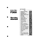
Summary of Contents for F300

Page 1: ...STEM LUBRICATION SYSTEM IGNITION SYSTEM STARTING SYSTEM CHARGING SYSTEM CLUTCH MANUAL TRANSMISSION TRANSMISSION TRANSFER PROPELLER SHAFT FRONT REAR DIFFERENTIAL FRONT AXLE SUSPENSION REAR AXLE SUSPENS...

Page 2: ...DAIHATSU F300 STARTING SYSTEM OUTLINE OF STARTING SYSTEM ST 2 DESCRIPTION ST 5 PLANETARY TYPE STARTER MOTOR ST 10 REDUCTION TYPE STARTER MOTOR ST 24 ST 1...

Page 3: ...n the engine flywheel The planetary type starter motor is a reduction type starter which employs a planetary gear set Compared with the conventional starter motors this reduction type starter motor fe...

Page 4: ...gear The rotation speed is reduced in accordance with the gear ratio between the drive gear provided at the motor and the clutch gear On the other hand the torque of the rotation increases j Bearing A...

Page 5: ...lace fusible link Starter faulty Repair starter Ignition switch faulty Replace ignition switch Engine cranks Slowly Battery not fully charged Check specific gravity of battery electrolyte Charge or re...

Page 6: ...tary gear starts to walk around the sun gear while the planetary gear itself is turning on its own shaft In as much as the planetary carrier is integral with the planetary gear shaft the torque is tra...

Page 7: ...the engine The solenoid is composed of two coils One is a low resistance coil which moves the shift fork which corresponds to the pinion shaft 1n the case of the reduction type starter motor The other...

Page 8: ...act points and cutting the current to the motor At the same time the shift fork or the pinion shaft which has been pushing the pinion gear returns to the original position by means of the aforesaid sp...

Page 9: ...er in the clutch housing positively and be sure to tighten the attaching bolts to the specified torque Improper installation can cause premature wear of the teeth of the pinion gear or ring gear and a...

Page 10: ...2 Jack up the vehicle and support it with safety stands 3 Disconnect the starter terminals STand 8 from the starter 4 Remove the starter motor from the clutch housing ST 9 STARTING SYSTEM...

Page 11: ...ch ter minaL Connect the negative terminal of the battery to the starter body and magnetic switch terminal Connect the positive terminal to the terminal ST Ensure that the pinion is pushed ouward If t...

Page 12: ...attery and an ammeter to the starter as shown in the right figure Ensure that the starter rotates smoothly with the pinion moving out Measure the current the starter is drawing Specified Current Less...

Page 13: ...the yoke with armature from the clutch with center bearing 7 Remove the o ring 8 Remove the end frame cover by removing the two screws 9 Remove the brushes from the brush holder by lifting the brush s...

Page 14: ...12 Remove the stop collar from the snap ring by tapping the collar with a screwdriver or the like placed on it 13 Detach the snap ring by prying it off with snap ring pliers Then remove the collar 14...

Page 15: ...the commutator using an ohmmeter If no continuity exists between any adjacent segments replace the armature Check of commutator 1 Check each contact surface of the commutator segments with the brushes...

Page 16: ...id coil continuity test Perform f1eld coil continuity test at a point between the lead wire and the brush using an ohmmeter If no continuity exists replace the yoke 2 Reid coil short test Perform fiel...

Page 17: ...hing it with pliers NOTE Be sure to take out the brush lead wire in the correct direction Solder the pressure connection section Correct the section using a file or the like so that the section con fo...

Page 18: ...ure that the pinion turns smoothly Turn the pinion counterclockwise Ensure that the pinion is locked If the check results are unsatisfactory replace the starter clutch Check at magnetic switch 1 Plung...

Page 19: ...of the center bearing so as to determine the clearance Specified Value 0 04 mm Allowable Umit 0 15 mm If the clearance exceeds the allowable limit replace the oilless bearing or the planetary carrier...

Page 20: ...s to determine the clearance Specified Value 0 04 mm Allowable Umit 0 15 mm If the clearance exceeds the allowable limit replace the oilless bearing or the armature 3 Bearing replacement D Remove the...

Page 21: ...f the clearance exceeds the allowable limit replace the oilless bearing or the armature 3 Bearing replacement CD Remove the bearing using a tap having an outer diameter of 8 mm NOTE Be certain to clam...

Page 22: ...uter periphery of the internal gear with the protruded section provided at the inner periphery of the center bearing 2 Put the plate washer onto the planetary carrier shaft Then install the center bea...

Page 23: ...aring 8 Install the yoke to the armature Install the brushes to the brush holder while lifting the brushes by means of nose pliers or the like 9 Install the commutator end frame together with a new 0...

Page 24: ...oke during the assembly 12 Install the two through bolts 13 While hooking the magnetic switch over the drive lever install the magnetic switch onto the drive housing Secure the magnetic switch with th...

Page 25: ...er minal Connect the negative terminal of the battery to the starter body and magnetic switch terminal Connect the positive terminal to the terminal ST Ensure that the pinion is pushed outward If the...

Page 26: ...ction is carried out 4 No load Performance Test Connect the battery and an ammeter to the starter as shown in the right figure Ensure that the starter rotates smoothly with the pinion moving out Measu...

Page 27: ...move the brushes from the brush holder by means of nose pliers or the like NOTE Care must be exercised not to damage the brushes during the removal 7 Remove the armature from the yoke being very caref...

Page 28: ...ure coil using an ohmmeter If continuity exists replace the armature 2 Check of commutator continuity Check continuity between each adjacent segment of the commutator using an ohmmeter If no continuit...

Page 29: ...minimum diameter replace the armature 4 Check of commutator undercut Measure the insulator groove depth between the com mutator segments Minimum Depth 0 2 mm If the insulator groove depth becomes less...

Page 30: ...sistance is less than the specifiCation replace the brush holder Inspection of clutch 1 Inspection of pinion gear and spline teeth Check the teeth of the pinion gear and spline for wear or damage If t...

Page 31: ...nd Ensure that the bearing turns smoothly If the bearing fails to turn smoothly replace the bearing 2 Replacement of bearings Only when bearing is faulty CD Remove the bearing using an armature bearin...

Page 32: ...r which exhibits damage or wear 2 Inspect the starter idle gear bearing and bearing housing for damage or wear Replace the clutch or retainer as required ASSEMBLY OF REDUCTION TYPE STARTER MOTOR NOTE...

Page 33: ...ic switch assembly in the starter drive housing Secure the switch assembly with the two screws 5 Insert the armature into the yoke 6 While the brush holder is held in a raised state by means of a scre...

Page 34: ...1 Install the starter motor to the clutch housing 2 Dghten the attaching bolts of the starter motor to the specified torque TighteningTorq Je 5 0 7 0 kg m 36 2 50 6 ft lb 49 0 68 6 N m 3 Connect the s...

Page 35: ...M 1 COMPONENTS CH 2 2 CHARGING SYSTEM CIRCUIT CH 3 3 TROUBLE SHOOTING CH 3 4 DESCRIPTION CH 4 5 IN VEHICLE INSPECTION CH 7 6 REMOVAL CH 8 7 DISASSEMBLY CH 9 8 INSPECTION CH 11 9 ASSEMBLY CH 17 10 INST...

Page 36: ...lley lock nut Alternator pulley Drive end frame assembly Stud bolt Bearing Retainer plate Alternator rotor assembly Washer Bearing 0 Bearing cover Wave washer Rectifier end frame assembly 0 Rectifier...

Page 37: ...Lamp bulb burnt Replace bulb glow even if ignition switch is Poor connection of wiring Repair poor connection of wiring turned ON Open wire Repair or replace IC regulator faulty Replace regulator ass...

Page 38: ...current to direct current at a low cost Con sequently alternators AC generators have been commonly used The following are advantages of alternators compared with DC generators 1 Compact design light w...

Page 39: ...ect the three pairs of stator coils a uy connecting method is employed Atthough this Y connecting method is inferior to a Delta type connecting method in the maximum output current the Y connecting me...

Page 40: ...er the latest alternators have employed two more diodes for the purpose of utilizing the electromotive force at the neutral point As a result the latest alternator can produce a greater output current...

Page 41: ...nomenon If the voltage reading is less than the standard voltage ground the terminal F as indicated in the right figure Proceed to start the engine If the voltage reading becomes greater than the stan...

Page 42: ...from alternator i Remove the nut and wire from the alternator Disconnect the connector from the alternator 3 Removal of alternator drive belt Loosen the alternator attaching bolts Remove the drive bel...

Page 43: ...re to use an impact wrench having a hexagonal hole 2 Removal of rear end cover D Remove the nut and terminal insulator Remove the three screws Remove the rear end cover 3 Remove the brush holder 4 Rem...

Page 44: ...older 6 Remove the rectifier end frame from the drive end frame by removing the two nuts and bolts NOTE Be very careful not to damage the stator wire If any difficulty is encountered in the removal li...

Page 45: ...o continuity exists between the rotor slip rings and the rotor core If continuity exists replace the rotor Inspection of slip rings a Check to see if the slip ring surface exhibits rough ness abnormal...

Page 46: ...length Measure the exposed brush length using a scale Standard exposed length 10 5 mm Minimum exposed length 1 5 mm If the exposed length is less than the minimum require ment replace the brushes Rep...

Page 47: ...nd of the brush wire To facilitate soldering Route the wire through the holder hole and adjust the exposed length of the brush tothe specification Bend the wire at its forward end on which solder has...

Page 48: ...in the step a or in the step b and no continuity exists at the other test If not replace the rectifier holder Inspection of rectifier at negative 8 side a While using an ohmmeter connect one tester pr...

Page 49: ...ng ll necessary a Remove the four screws and retainer plate b Remove the front bearing from the drive end frame using a socket wrench in conjunction with a press c Press the new front bearing into the...

Page 50: ...cement of rear bearing if necessary a Remove the rear bearing and bearing cover from the rotor using the armature bearing puller NOTE Be very careful not to damage the fan during the removal b Press a...

Page 51: ...re during the installation If some resistance is encountered during the insertion lightly tap the frame with a plastic hammer 3 Installation of rectifier holder regulator assembly and brush holder CD...

Page 52: ...6 Installation of rear cover j Install the rear end cover with the three attaching screws Install the terminal insulator and tighten it with the nut 7 Attach the pulley to the alternator shaft 8 Tight...

Page 53: ...CHARGING SYSTEM 11 Ensure that the rotor turns smoothly CH 19...

Page 54: ...n in such a way that the deflection of the drive belt meets the specification when you push the midpoint of the drive belt between he alternator pulley and the water pump pulley by applying a force of...

Page 55: ...CHARGING SYSTEM 4 Reconnect the ground cable terminal to the negative terminal of the battery CH 21...

Page 56: ...CL 6 INSPECTION CL 7 INSTALLATION CL 9 CLUTCH PEDAL L H D CL 12 COMPONENTS CL 12 REMOVAL CL 13 INSPECTION Clutch pedal Release cable CL 15 INSTALLATION CL 16 CLUTCH PEDAL R H D CL 19 COMPONENTS CL 19...

Page 57: ...and excellent serviceability release lever yoke Input release bearing hub Clutch disc specifications Clutch disc outer diameter mm 200 Clutch disc inner diameter mm 140 Thickness Rywheel side mm 3 5...

Page 58: ...CLUTCH RELEASE The clutch release lever yoke is attached to the clutch release lever by means of a bolt Furthemore an anti vibration weight is provided at the outer lever section Anti vibration weigh...

Page 59: ...section to the pedal is therefore necessary to roll up the carpet and floor mat prior to the measurement Tightening Torque 17 7 29 4 N m 1 8 3 0 kgf m 2 Adjust the pedal installation height as requir...

Page 60: ...dal Adjust free travel or clutch pedal travel Dragging clutch travel improperly adjusted Deformed clutch disc Check clutch disc Clutch disc spline malfunctioning Check clutch disc Abnormal surface of...

Page 61: ...ater pump pliers CAUTION Never reuse the lock washer 4 Remove the bolt tightened to the clutch release lever 5 Remove the torsion spring from the release lever yoke using a standard screwdriver NOTE C...

Page 62: ...clutch release bearing hub assembly as a set from the front bearing retainer 9 Remove the release lever yoke from the release bearing hub clip by turning the release lever yoke clockwise CAUTION If th...

Page 63: ...ng for wear 2 Release bearing hub clip for damage 3 Inner race of release bearing for wear 5 Rotate the release bearing with your fingers Ensure that the release bearing rotates smoothly without any b...

Page 64: ...SST 09301 87601 000 Tightening Torque 14 7 21 6 N m 1 5 2 2 kgf m CAUTION Be sure to tighten the bolts diagonally within the tighten ing torque range above so that the clutch cover may be tightened ev...

Page 65: ...e NOTE Prior to the setting apply a suitable amount of Lithium base multi purpose grease A section to the clutch release bearing hub or to the sliding surface with the release lever yoke 8 Apply molyb...

Page 66: ...pliers NOTE Never use a chisel for this operation If a chisel or the like should be used for bending the lock plate the release beartng hub dip may be detaohed 15 Apply the torsion spring to the relea...

Page 67: ...H PEDAL L H D COMPONENTS CD Clutch release cable assy E Ring Clutch cable inner holder Bush Bush ll Spring 0 Spacer Cushion I I I I I I I I I I I I I I I Clutch pedal S A CL 12 T Tightening torque Uni...

Page 68: ...le of the hood opener cable by removing the two screws 3 PuU out the instrument light control switch knob toward you 4 Remove the two screws at the instrument panel light control switch 5 Remove the t...

Page 69: ...nsert a standard screwdriver into between the return spring and the clutch pedal Release the return spring which hooks at the clutch pedal by lowering the standard screwdriver 10 At the lower side of...

Page 70: ...ing installed INSPECTION Clutch pedal Release cable 1 Visually inspect the eye end s ring section of the clutch release cable assembly and clutch pedal assembly for wear or damage 2 Visually inspect t...

Page 71: ...TALLATION 1 Apply Lithium base multi purpose grease to the eye end section of the clutch cable and inner cable 2 Temporarily insert the clutch cable into the cable insertion hole 3 After applying Lith...

Page 72: ...ly 8 Attach the return spring to the clutch pedal and pedal bracket using a common tool of a standard screwdriver NOTE Apply Lithium base multi purpose grease to the clutch cable and the installation...

Page 73: ...ight control switch 12 Install the hood opener cable 13 Install the instrument panel finish lower panel with the four screws 14 Install the handle of the hood opener cable with the two screws 15 Inser...

Page 74: ...PEDAL R H D COMPONENTS CD Hood lock control lever S A Instrument panel finish lower panel Hood lock control cable Ay Nut Return spring Bolt j Clutch pedal S A CL 19 CLUTCH T Tightening Torque UnH N m...

Page 75: ...ove the clutch cable assembly and clutch cable inner holder from the engine compartment side 2 Remove the hood opener cable handle 3 Remove the instrument panel finish lower panel 4 Disconnect the hoo...

Page 76: ...CLUTCH 6 Remove the return spring 7 Remove the clutch pecal shaft bolt 8 Remove the clutch pedal subassembly CL 21...

Page 77: ...e items given below Replace any defective parts 2 Move the inner cable of the clutch release cable in a fore aft direction Ensure that no abnormal resistance or bind ing is present 3 While holding the...

Page 78: ...i purpose grease to the clutch cable installation section of the clutch pedal 2 Insert the clutch pedal shaft bolt from the left side of the pedal bracket Tighten the bolt Tightening Torque 14 7 21 6...

Page 79: ...t the nut so that the pedal free travel may conform to the specified value Pedal Free Travel 18 27 mm NOTE Apply Lithium base multi purpose grease to the clutch pedal installation section of the clutc...

Page 80: ...the cultch cable inner holder A should be inserted to the cut off section of the dash panel 11 Install the clutch cable at the clutch release lever side Install the clutch cable assembly to the transm...

Page 81: ...tch disc Runout 1 0 Longitudinal 0 7 Lateral Clutch cover Variation height of diaphragm spring 0 8 Height 221 5 RHD LHD Free travel 18 27 WFE90 CL 96 TIGHTENING TORQUE Tightening components Tightening...

Page 82: ...AFT MT 28 TRANSFER ADAPTER MT 31 INPUT SHAFT MT 32 HUB SLEEVE SYNCHRONIZER RING GEARS MT 33 OUTPUT SHAFT MT 36 COUNTER GEAR REVERSE IDLER GEAR RELATED PARTS MT 36 ASSEMBLY OF CLUTCH HUB MT 38 TRANSMIS...

Page 83: ...ilable on all models A center through type transfer is employed in which the power train components from the input shaft to the output shaft are arranged straight in one row The transmission controls...

Page 84: ...1 754 part time only Transfer Kind API GL 3 or GL 4 SAE 75W S5or Oil used 75W 90 Capacity 1 4 L Transmission and transfer teeth number General specification Input shaft gear 23 Driven gear 34 1st gea...

Page 85: ...NISM The transmission control shaft is connected to the shift select No 1 shaft by means of a cross joint When the transmission control shaft is moved in the selecting direction the shift inner lever...

Page 86: ...e for the control shaft to be shifted into the reverse gear Fig 1 Reverse restrice p1n No 2 Contact 0 0 0 0 ONE WAY MECHANISM When the transmission control shaft is shifted into the 5th gear position...

Page 87: ...related Check control related components Slipping out of gear components Abnormal noise from bearing Bearing seizure Abnormal wear Check bearing and gear for seizure Malfunctioning control related Che...

Page 88: ...being used only in conventional models The coating colors for identification between the full time transmission with transfer assembly and the part time transmission with transfer assembly are as fol...

Page 89: ...val be sure to put a scribing line If this operation should fail to be performed the propeller shaft may emit abnormal noise or vibration 4 Remove the front propeller shaft CAUTION Prior to the remova...

Page 90: ...ll the rear propeller shaft 4 Tightening Torque 58 8 78 5 N m 6 0 8 0 kgf m CAUTION Install the propeller shaft while aligning the scribing lines which were put during the removal If this operation sh...

Page 91: ...xposed machined surface of the differential slant line section in the right figure as a rust preventive measure_ 6 Install the transmission undercover with the eight bolts 7 Fill the transfer with oil...

Page 92: ...amage u t n1 mm Part Specified value Limit Driven gear shaft diameter j 8 fl 7 96 Shaft sleeve bore 8 g 8 10 Oil seal lip section 0 ring Visually inspect the section for excessive wear or damage Drive...

Page 93: ...ng the six bolts and then pull up toward you 4 Remove the transmission control lever by detaching the snap ring using the common tool of snap ring plier 5 Remove the transfer control lever by removing...

Page 94: ...one both under the starter motor 3 Working from the vehicle outside 1 Jack or ntt up the vehicle and support the vehicle body with safety stands securely As for the jack or lift up points refer with...

Page 95: ...eedometer cable with oil seal from the transmission case using the common tool of plier 6 Remove the front propeller shaft and rear propeller shaft by removing the four bolts and four nuts CAUTION Whe...

Page 96: ...s 8 Remove the exhaust pipe support bracket by removing the three bolts 9 Remove the two attaching nuts at the crossmember No 2 10 Remove the exhaust pipe bracket attaching to the crossmember No 3 by...

Page 97: ...an and the fan shroud 13 Support the transmission with a transmission jack 14 Remove the crossmember No 2 by removing the four bolts on both left and right sides 15 While supporting the transmission w...

Page 98: ...TRANSMISSION PART TIME COMPONENTS MT 17 MANUAL TRANSMISSION WFEOO MT051...

Page 99: ...mesh shifting key No 2 Synchronizer ring No 2 Output shaft gear spacer No 2 Output shaft gear spacer No 1 5th gear Radial ball bearing I 1st gear thrust washer 1st gear bearing inner race 1st gear S L...

Page 100: ...MANUAL TRANSMISSION INPUT SHAFT OUTPUT SHAFT COUNTERSHAFT RELATED COMPONENTS MT 19 0 Ttghtening torque Unit N m kgf rn No reusable parts 1ll Selection parts WFE90 MT053...

Page 101: ...roller bearing 1st gear bearing inner race 1st gear bearing inner race No 2 1st gear thrust washer Radial ball bearing Snap ring Conical spring washer Washer plate Sub gear No 1 Transfer low speed in...

Page 102: ...n the overhauling stand as shown in the diagram at right 3 Support the transfer front and transfer rear case with a transmission jack 4 Remove the control shaft with installed the shift lever retainer...

Page 103: ...l the overhauling stand as shown in the diagram at right 3 Support the transfer front and transfer rear case with a transmission jack 4 Remove the control shaft with installed the shift lever retainer...

Page 104: ...15 Remove the gasket on the transfer adapter with a gasket scraper NOTE Remove the gasket on the transmission case attaching surface of the transfer adapter using a gasket scraper Be very careful not...

Page 105: ...gear NOTE Never reuse the removed lock nut 20 Remove the conical washer spring and shifting key retainer 21 Drive off the slotted pin of the 5th shift fork NOTE Never reuse the removed slotted pin 22...

Page 106: ...r race 3 5th gear thrust washer 26 Remove the liquid gasket from the transmission case using a gasket scraper NOTE Be very careful not to scratch the transmission case during the removal 27 Remove the...

Page 107: ...g of the input shaft using the following SST SST 09905 00012 000 NOTE Never reuse the removed snap ring 32 Remove the input shaft bearing using the following SST SST 09306 87602 000 NOTE Detach the st...

Page 108: ...ssembly As for the disassembly inspection and assembly for the removed parts see page MT 28 NOTE It is recommended that as shown in the diagram at right an operation rope about 3 mm in outside diamete...

Page 109: ...9 Remove the reverse shift arm and 5th shift arm TRANSMISSION OUTPUT SHAFT DISASSEMBLY 1 Remove the 1st gear thrust washer 2 Remove the 1st gear 3 Remove the synchronizer ring No 2 4 Remove the needle...

Page 110: ...rse gear with installed the following parts in a set 1 Transmission clutch hub No 1 2 Synchromesh shifting key spring 3 Synchromesh shifting key 7 Remove the synchronizer ring 8 Remove the 2nd gear 9...

Page 111: ...learance of transmission clutch hub No 2 should be measured prior to assembly the above parts See page MT 39 11 Detach the snap ring NOTE Never reuse the removed snap ring 12 Remove the following part...

Page 112: ...2 Conical spring 3 Washer plate 4 Sub gear No 1 2 Remove the bearing of the transmission output shaft of the transfer adapter by pushing the output gear spacer No 2 to the transfer front case side 3...

Page 113: ...ly without any binding 1 Transfer counter gear of the transfer adapter 2 Transmission output shaft of the transfer adapter INPUT SHAFT 1 Check the input shaft for the following items 3 1 Spline sectio...

Page 114: ...t fork using vernier calipers Unit mm m Specified value Allowable limit e Transmission hub sleeve 7 05 7 12 7 3 3 Measure the clearance between each gear and the synchronizer ring using a thickness ga...

Page 115: ...maximum value is regarded as the contact width for the said ring 5 Measure the height of each synchromesh shifting key using vernier calipers Unit mm m Specified value Allowable limit M 1st 2nd gears...

Page 116: ...tch No 1 hub 69 78 69 84 2 Reverse gear 69 871 69 97 TIM clutch No 2 hub Synchronizer No 1 hub 69 68 69 74 1 TIM hub No 1 sleeve T M hub No 2 sleeve 69 971 69 87 69 58 69 64 3 69 67 69 77 8 With the s...

Page 117: ...asure the runout of the output shaft using a dial gauge and V block Allowable Runout Limit 0 05 mm 2 Check the gear section of each gear for damage or abnor mal wear 3 Check each needle roller bearing...

Page 118: ...Conical spring washer 4 Snap ring NOTE Never reuse the removed snap ring Install the conical spring washer with its expanded side facing toward the sub gear No 1 2Press a new oil seal from the bearin...

Page 119: ...the synchromesh shifting key spring the bent sections at the front and rear should not come at the same direction as shown in the right figure TRANSMISSION OUTPUT SHAFT ASSEMBLY 1 Apply the gear oil...

Page 120: ...ces of the synchromesh shifting key spring to the output shaft 8 Install the synchromesh shifting key three pieces to the transmission clutch hub No 2 and then install the transmis sion clutch hub No...

Page 121: ...utput shaft in a set 1 Synchromesh shifting key Three pieces 2 Synchromesh shifting key spring Two pieces 3 Transmission clutch hub sleeve No 1 NOTE Make sure that the sleeve section of the reverse ge...

Page 122: ...ll the reverse shift arm and 5th shift arm 2 Install the reverse idler gear shaft and reverse idler gear NOTE Be sure to install the reverse idler gear shaft in such a way that the cut out section of...

Page 123: ...llowing SSTs at the same time SSTs 09304 87601 000 09309 87201 000 6 Apply the gear oil to the needle roller bearing and then install to the output shaft 7 Install the synchronizer ring No 3 8 Press t...

Page 124: ...2 Apply molybdenum disulphide lithium base grease to the clutch hub sliding section of the front bearing retainer Tightening Torque 14 7 21 6 N m 1 5 2 2 kgf m 3 Be sure to tighten the bolts alternate...

Page 125: ...appered section 3 Synchronizer ring 19 Apply the gear oil to the gear shifting lever shaft and then insert to the transmission case NOTE Make sure that cut out section of the gear shifting lever faces...

Page 126: ...1 Fully hand tighten the lock nut on the fifth gear of the countershaft 2 Engage each gear in order of the manual transmission shift position 3 Visually check that both the input shaft and the output...

Page 127: ...ht figure illustration Band C 26 Install the output gear spacer No 1 and No 2 to the output shah 27 Apply gear oil to the outer periphery of the output gear spacer No 2 28 Apply the following bond to...

Page 128: ...chisel as below illustra tion securely Tightening Torque 177 0 216 0 N m tB O 22 0 kgf m NOTE When staking the lock nut point a suitable staking tool toward the transmission output rear shaft axis cen...

Page 129: ...have come into firm contact Failure to observe the caution may bend the subgears thus causing gear noise from the transmission 35 Tighten the transfer front case subassembly with the eight bolts Tight...

Page 130: ...rque 14 7 21 6 N m 1 5 2 2 kgf m A section 6 9 9 8 N m 0 7 1 0 kgf m 38 Install the shift lever retainer subassembly and the control shaft with a hexagon bolt Use new hexagon bolt Tightening Torque 14...

Page 131: ...Torsion spring Slotted pin Shift inner lever Q Detent sleeve Oil seal Tight plug 9 Ball Set bolt Spring Gasket Reverse restrict pin holder Shift fork lock plate Bolt 1st 2nd shift fork shaft 1st 2nd...

Page 132: ...3 000 3 Remove the shift lever retainer subassembly and the control shaft by removing the hexagon bolt 4 Remove the transmission case cover subassembly by removing the seven bolts and a reamer bolt 5...

Page 133: ...he transmission case subas sembly using a standard tool of magnet hand 5 Turn the transmission case cover subassembly through 180 degrees 6 Remove the backup lamp switch assembly and the gasket NOTE N...

Page 134: ...e removed slotted pin 9 Remove the E ring of the 3rd 4th shift fork using the standard tool of flat driver NOTE Never reuse the removed E ring 10 Remove the 1st 2nd shift fork shaft by inserting the f...

Page 135: ...e or couterclockwise 11 Remove the 3rd 4th shift fork shaft using the following SST SST 09339 87301 000 NOTE Removal of shift fork shaft is same manner with the 1st 2nd shift fork shaft 12 Drive off t...

Page 136: ...hift fork 18 Detach the snap ring of the shift select shaft No 1 and slightly move to toward the and of transmission case cover subassembly 19 Drive off the slotted pin of the shift inner lever When d...

Page 137: ...shaft boot installed 23 Remove the shift fork lock plate and torsion spring by removing the hexagon bolt 24 Disconnect clamp of the breather hose 25 Remove the union 26 Remove the oi seal using the c...

Page 138: ...Unit mm p Specified value Allowable limit Reverse shift fork Dimension C in 15 000 15 043 15 1 right figure 3 Measure the contact width of the gear shift head No 1 with 5th shift arm using vernier cal...

Page 139: ...amage 6 Visually inspect the reverse restrict pin No 2 for wear or damage 7 Check the spring for damage 8 Check the spring of the shift fork shaft for damage 9 Check the balls of the reverse restrict...

Page 140: ...ontrol shaft No 2 boots to the shift select shaft subassembly 2 Apply Lithium base multi purpose grease to the lip section of the oil seal and then drive the oil seal 1nto the transmis sion case cover...

Page 141: ...t inner lever to the shift select shaft No 1 8 Install the torsion spring to the shift select shaft No 1 NOTE Apply Lithium base multi purpose grease to the torsion spring installation section of the...

Page 142: ...ration 1 Move the shift select shaft No 1 in the shifting direc tion Ensure that it operates smoothly 2 Move the shift select shaft No 1 in the selecting direction Ensure that it operates smoothly 13...

Page 143: ...ed SST by pushing the small sized SST with your fingers 6 Install the 5th reverse shift fork shaft by pushing the small sized SST NOTE At this stage install the compression springs and balls for the 1...

Page 144: ...0 Install the 3rd 4th shift fork shaft to the transmission case cover subassembly NOTE Apply the gear oil to the outer periphery of the 3rd 4th shift fork shaft prior to install 21 Attach the new QEH...

Page 145: ...shafts to put the gear into the neutral position NOTE Make sure that the long notch sections of the shift fork shafts are arranged uniformly 26 Inspection of operation Select the shift select shaft N...

Page 146: ...0 5 0 kgf m 29 Tighten the reverse restrict pin with the two balls and com pression spring use new gasket Tightening Torque 29 4 49 0 N m 3 0 5 0 kgf m 30 Tighten the set bolt with a spring washer Tig...

Page 147: ...e 14 7 21 6 N m 1 5 2 2 kgf m A section 6 9 9 8 N m 0 7 1 0 kgf m 35 Install fit the control shaft No 2 boot to the oil seal groove section securely NOTE Air breeding hall A in the control shaft No 2...

Page 148: ...TRANSMISSION FULL TIME COMPONENTS MANUAL TRANSMISSION MT 67...

Page 149: ...No 2 Hub sleeve No 1 Synchromesh shifting key spring I Synchronizer ring No 3 3rd gear I Needle roller bearing I Output shaft 1st gear bearing inner race Needle roller bearing 9 2nd gear Synchronizer...

Page 150: ...MANUAL TRANSMISSION INPUT SHAFT OUTPUT SHAFT TRANSFER INPUT HUB COMPONENTS MT 69 D Tightening torque Unit N m kgf m Non reusable parts SelectiOn parts...

Page 151: ...g Synchronizer ring No 2 1st gear Needle roller bearing 1st gear bearing inner race 1st gear bearing inner race No 2 if D 1st gear thrust washer Radial ball bearing Oring Oil seal Bearing Oring 8 Tran...

Page 152: ...erhauling stand as shown in the diagram at right 3 Support the transfer front and transfer rear case with a transmission jack 4 Remove the control shaft with installed the shift lever retainer subasse...

Page 153: ...the transfer adapter and pull them toward you careful ly 11 Interlock the 1st gear and the 3rd gear NOTE Measure the following sections prior to an interlock Specified Value Unit mm ____ 1st 2nd 3rd 4...

Page 154: ...the removed 0 ring 16 Remove the liquid gasket in the attaching surface of the transfer adapter using the standard tool of gasket scraper NOTE Be careful not to damage the mating surface 17 Remove th...

Page 155: ...ce 0 11 0 30 20 Raise the lock section of the lock nut using the chisel or the like CAUTION Never reuse the removed lock nut 21 Remove the lock nut of the counter shaft 5th gear 22 Remove the conical...

Page 156: ...following parts from the countershaft 1 Needle roller bearing 28 2 5th gear bearing inner race 3 5th gear thrust washer Remove the liquid gasket from the transmission case using the standard tool of g...

Page 157: ...SST SST 09602 87301 QOO 32 Detach the snap ring of the countershaft using the following SST SST 09905 00012 000 NOTE Never reuse the snap ring 33 Detach the snap ring of the input shaft using the fol...

Page 158: ...ove the input shaft 37 Remove the needle roller bearing and synchronizer ring No 3 38 Remove the output shaft assembly As for the disassembly inspection and assembly for the removed parts see page MT...

Page 159: ...MANUAL TRANSMISSION 40 Remove the countershaft from the transmission case 41 Remove the reverse idler gear and reverse idler gear shaft 42 Remove the reverse shift arm and 5th shift arm MT 78...

Page 160: ...PUT SHAFT DISASSEMBLY 1 Remove the 1st gear thrust washer 2 Remove the 1st gear 3 Remove the synchronizer ring No 2 4 Remove the needle roller bearing 5 Remove the 1st gear bearing inner race MT 79 MA...

Page 161: ...No 2 8 Remove the 2nd gear 9 Remove the needle roller bearing 10 Remove the following parts 1 Transmission hub sleeve No 2 Synchromesh shifting key spring 1 piece 3 Synchromesh shifting key 3 pieces N...

Page 162: ...shifting key spring 1 piece 13 Remove the 3rd gear together with synchronizer ring No 3 14 Remove the needle roller bearing 15 Remove the synchromesh shifting key spring Remove the transmission hub sl...

Page 163: ...o see if the bearing inner race rotates smoothly without any binding and sticking 4 Input sha1 Check the input shaft for the following items 1 Spline section for damage 2 Gear for damage and wear 3 En...

Page 164: ...ring inner race for wear 4 Measure the runout of the output shaft using a dial gauge and V block Allowable Runout Umit 0 05 mm 8 Check the gear section of each gear for damage or abnor mal wear 9 Chec...

Page 165: ...synchronizer ring The maximum value is regarded as the contact width for the said ring 12 Measure the clearance between each gear and the synchronizer ring using a thickness gauge Unit mm m Specified...

Page 166: ...4th Front Synchronizer No 1 hub A 5th 16 The outer diameter dimension of the A above parts has been machined in accordance with the bore dimension of the B parts If either part exceeds the specified v...

Page 167: ...o 2 hub Synchronizer No 1 hub NOTE If the tilt width of the sleeves exceeds the above specified value be certain to replace those parts as a set 18 Measure the height of each synchromesh shifting key...

Page 168: ...ss direction of synchronizer hub assembly No 1 is present at the front end 3 Assemble the selected transmission clutch hub to the fol lowing parts using the synchromesh shifting key and synchromesh sh...

Page 169: ...sfer oil strainer suction tube to the transfer oil pump body subassembly using two bolts and tighten the bolts Tightening Torque 6 9 9 8 N m 0 7 1 0 kgf m CAUTION The bend section in the transfer oil...

Page 170: ...ar 4 Install the transmission clutch hub No 2 to the output shaft with the synchromesh shifting key 1 piece and synchronizer ring No 3 installed NOTE For easier installation of the synchromesh shiftin...

Page 171: ...Snap ring thickness 2 0 2 1 2 2 Unit mm 6 Install the following parts to the clutch hub No 2 and then install them to the output shaft 1 Synchromesh shifting key 3 pieces 2 Transmission hub sleeve No...

Page 172: ...key spring 2 pieces 2 Synchromesh shifting key 3 pieces 3 Transmission clutch hub No 1 NOTE Ensure that the bent sections at the front and rear of the synchromesh shifting key spring should not come...

Page 173: ...CASE BY REMOVING ANY DIRT GAS KET MATERIALS OR THE LIKE 1 Install the reverse shift arm and 5th shift arm 2 Install the reverse idler gear shaft and reverse idler gear NOTE Be sure to install the rev...

Page 174: ...n case 5 Apply the gear oil to the needle roller bearing and then Install to the output shaft 6 Install the synchronizer ring No 3 7 Press the input shaft bearing into position using the follow ing SS...

Page 175: ...side prior to install the stop ring 11 Install a new snap ring to the input shaft using the following SST SST 09304 87601 000 12 Install the stop ring to the input shaft 13 With a new gasket used inst...

Page 176: ...phery of the these parts 18 Apply gear oil to the tapered section of the 5th gear and install the 5th gear and the synchronizer ring No 3 to the counter shaft 19 Install the 5th gear shift fork and th...

Page 177: ...oil to the 0 ring NOTE Be very careful not to damage the new 0 ring during installation 26 Install the new lock nut of the 5th gear countershaft and then tighten them Tightening Torque 177 0 216 0 N m...

Page 178: ...ns mission case 30 31 NOTE Apply the bond to the inside of the bolt hole as shown in the diagram at right Apply gear oil to the outer periphery of the output gear spacer No 2 and to the lip section of...

Page 179: ...ernately and diagonally the right figure illustration is atypical example of tighten ing sequence 34 Install the new lock nut of the transmission output shaft and then tighten it Tightening Torque 177...

Page 180: ...to the 0 ring section of the transfer oil strainer tube 38 Shift the 1st gear into position 39 Tighten the transfer front case with the eight dummy bolts with rotating the input shaft clockwise CAUTI...

Page 181: ...diagonally The illustration at the right figure indicates a typical example of tightening sequence 42 Install the shift lever retainer subassembly and the control shaft with a hexagon bolt Use new he...

Page 182: ...g Torque 49 0 68 6 N m 5 0 7 0 kgf m 3 Tighten the cross member No 2 with the four bolts on both left and right sides bolts Tightening Torque 39 2 53 9 N m 4 0 5 5 kgf m 4 Remove the wooden pieces bet...

Page 183: ...aust pipe 7 Tighten the catalyst converter assembly with the M o nuts on both front and rear side using the new gaskets Tightening Torque 36 3 51 0 N m 3 7 5 2 kgf m NOTE Install the converter in such...

Page 184: ...eter cable has positively entered into the sleeve 11 Connect the coupler of back up lamp and transmission position detect switch 12 Connect the clutch release cable subassembly to the release fork NOT...

Page 185: ...over with the eight bolts Tightening Torque 39 2 58 8 N m 4 0 6 0 kgf m 2 Working from the vehicle outside 1 Jack down the vehicle 3 Working from the engine compartment room 1 Install the direct conne...

Page 186: ...NOTE Apply the Lithium base multi purpose grease to the for ward end of the transfer control lever 2 Install the transmission control lever with a snap ring using the common tool of snap ring plier CA...

Page 187: ...g 09306 87601 000 Replacer counter shaft bearing 09306 87602 000 Puller counter gear front bearing 09309 87201 000 Transmission bearing replacer w C J 09339 87301 000 Shift folk shaft guide w I lOCI I...

Page 188: ...th gear 5th gear Class Class Each hub sleeves and reverse gear tilt width Assembled to the each hubs Synchromesh shifting key groove width 1st gear Except 1st gear Synchromesh shifting key height Outp...

Page 189: ...ach gear 3rd gear 0 10 0 33 5th gear 0 11 0 30 Output shaft runout 0 05 Synchronize ring to shifting tst gear 9 9 10 1 key groove width Except gear 11 3 11 5 tstgear Synchronizer ring to 2nd gear gear...

Page 190: ...2 5 29 4 44 1 Shift lock plate x TIM case cover 1 5 2 2 10 8 15 9 14 7 21 6 Union x T tvl case cover 1 3 1 6 9 4 11 6 12 7 15 7 TRANSMISSION PART FULL TIME Tightening component Tightening torque kgf m...

Page 191: ...COMPONENTS TR 25 REMOVAL TR 27 DISASSEMBLY OF TRANSFER OUTPUT FRONT REAR TR 36 DISASSEMBLY OF TRANSFER COUNTER GEAR TR 37 INSPECTION TR 38 ASSEMBLY T F OUTPUT FRONT COUNTER GEAR and REAR TR 43 TR 1 IN...

Page 192: ...is made into the transfer front drive gear Then the power is transmitted to the transfer output front shaft through the transfer front drive chain finally driving the front and rear wheels When the t...

Page 193: ...the center of the ball nearly reaches the outer contour of the transfer high low shift fork Shaft as shown by in the figure below the transfer high low shift fork shaft is in a locked state Transfer f...

Page 194: ...time a wait mechanism ie Compression spring functions owing to the resistance by a twisting torque between the front drive clutch hub and the front drive gear As a result the front drive shift fork is...

Page 195: ...fork shaft turns to the left as shown in Rg 1 below Simultaneously the roller moves and fits into the groove of the transfer front drive fork shaft As a result the transfer front drive shift fork shaf...

Page 196: ...fer control shaft is shifted to the 4L direction the transfer high low shift fork shaft alone moves to the right thereby attaining the 4L condition Transfer high low shift fork shaft 4L condition TR 6...

Page 197: ...ided on the transfer rear output shaft in the transfer This center differential absorbs any difference in rotation betvveen the front wheels and the rear wheels which may occur while turning under the...

Page 198: ...umber of driven gear teeth Identification Power train system Gear type Number of teeth Straight bevel gear 16 Straight bevel gear 10 Spur gear 33 Spur gear 33 6 24 The switching between the free posit...

Page 199: ...cover is combined with the transfer front drive hub thereby eliminating the differential function of the center differential As a result the power from the transmission output shaft is d lstributed e...

Page 200: ...d to the rear wheels in the same way as the center differential locked state However since the differential lock sleeve moves to the free position the differential case is dis engaged from the transfe...

Page 201: ...eels The side gear indicated at the right side of the f1gure below is spline connected to the transfer front drive hub The driving power from the side gear is transmitted to the front drive gear by th...

Page 202: ...each of the differential gear section needle roller bearing and rear output bush Check ball for relief valve Trochoid pump WFE9Q Tll0t3 3 Transfer input hub The transfer input hub is provided to trans...

Page 203: ...ime 4WD vehicle A groove is provided at the shaft section for the purpose of distinguishing this part from that for the part time 4WD vehicle 5 Transfer output rear shaft The shape is different from t...

Page 204: ...ys a spur gear The transfer front drive gear comes in three kinds because of installation requirements r d__ l f WFE90 TR017 Transfer front drive gear specifications Unit mm Dimension Classification 8...

Page 205: ...r front drive shift fork shaft is locked by the ball Thus the differential lock shift fork shaft alone moves to the right At this time if there is any difference in rotating torque between the front w...

Page 206: ...tions Therefore never drive the vehicle always under the 2WD mode 1 Procedure for switching from 4WD to 2WD 1 Jack up the vehicle 2 2 Loosen the bolt located at the lower section of the retainer in th...

Page 207: ...ve shaft lock sleeve moves to the right Consequently the transfer front drive hub is disengaged from the transfer front drive gear Namely the power from the manual transmission output shaft is not tra...

Page 208: ...direction as indicated in Fig 2 below Moreover when the transfer shift lever is shifted as indicated in the figure below the transfer fork shaft pin secured to the transfer front drive shift fork shaf...

Page 209: ...t alone moves to the right thus switching to the 2WD condition Transfer differential lock shift fork shaft Transfer front drive shift fork shaft 2WD condition Position Switch The switch is turned ON w...

Page 210: ...th the center differential for the full time 4WD vehicle The lubrication of the oil pump is performed as follows The oil is filtered by a strainer and sucked through the oil tube by the pump Then the...

Page 211: ...ner When changing the oil drain the oil from the drain plug located at the lower back side of the transfer Fill oil from the oil filling port up to the following level Transfer oil to be used Ammix su...

Page 212: ...1 754 part time only Transfer Kind API GL 3 or GL 4 SAE 75W 85 or Oil used 75W OO Capacity 1 4L Transmission and transfer teeth number General specification Input shaft gear 23 Driven gear 34 1st gea...

Page 213: ...related Check control related components Slipping out of gear components Abnormal noise from bearing Bearing seizure Abnorma wear Check bearing and gear for seizure Malfunctioning control related Che...

Page 214: ...atter being used only in conventional models The coating colors for identification between the full time transmission with transfer assembly and the part time transmission with transfer assembly are a...

Page 215: ...TRANSFER PART TIME COMPONENTS T M Output shaft TR 25 TRANSMISSION TRANSFER 0 Tightening torque Unit N m kgt m Non reusable parts Selection parts...

Page 216: ...ransfer front drive gear Transfer output gear thrust washer Radial ball bearing Lock nut Ball Speedometer drive gear Snap ring Transmission position detecting switch Gasket RoUer Roller Spring I Bolt...

Page 217: ...transmission jack 4 Remove the control shaft with installed the shift lever retainer subassembly by removing the hexagon bolt NOTE When disconnecting the control shaft from the shift select No 1 shaft...

Page 218: ...output shaft bearing retainer 1 Remove the eight bolts 2 Remove the transfer output shaft bearing retainer by tapping the both right and left ribs section using the wooden bar with plastic hammer lig...

Page 219: ...ing the seven bolts and the reamer bolt 13 Interlock the 1st gear and the 3rd gear 14 Raise the lock section of the lock nut 15 Remove the lock nut from the transfer output rear shaft using the follow...

Page 220: ...Remove the transfer front drive shift head 18 Remove the transfer fork shaft pin 19 Remove the E ring Remove the transfer high low shift head 20 Remove the E ring 21 Drive out the slotted pin of the t...

Page 221: ...e transfer rear case by lightly tapping the ribs section using the wooden bar with plastic hammer 24 Remove the gasket and transfer oil supply pipe 25 Remove the bearing using the following SSTs SST 0...

Page 222: ...plastic hammer Pull out the transfer output rear shaft and transfer front shaft with installed the transfer front drive chain toward you B 28 Remove the needle roller bearing and transfer front drive...

Page 223: ...ork shaft and gasket NOTE Never reuse the removed gasket 35 Remove the compression spring and ball using the stand ard tool of magnet hand 36 Turn the transfer front drive shift fork shaft 180 degree...

Page 224: ...the inspection for the removed parts see page TR 41 38 Remove the roller using the common tool of magnet hand 39 Remove the transfer front case by removing the seven bolts 40 Remove the gasket on the...

Page 225: ...d E rings 42 Remove the transfer high low shift fork 43 Pull out the transfer high low shift fork shaft toward you 44 Detach the stop ring of the transfer output rear shaft bear ing 45 Remove the tran...

Page 226: ...in a vice with transfer output front shaft installed Remove the bearing at the rear side of the transfer output front shaft using the following SST SST 09950 20017 000 Remove the bearing at the front...

Page 227: ...move the sub gear No 2 INSPECTION FRONT DRIVE CHAIN 1 Check the contacting surface of the transfer front drive chain with each gear for damage 2 Transfer front drive gear 1 Check the contacting surfac...

Page 228: ...ns fer front drive gear measure the tilt width at the section B of the differential lock sleeve Specified Value Not to exceed 0 5 mm NOTE If the tilt width of the differential Jock sleeve exceeds the...

Page 229: ...inger Check to see if the bearing inner race rotates smoothly without any binding 4 Transfer low speed output gear Check transfer row speed output gear for wear or damage 5 Transfer output rear shaft...

Page 230: ...sleeve as shown in the right figure Make sure that the clearance X between this shaft and the sleeve may confirm to the specification Specified Valve 0 03 0 19 mm 1 The outer diameter dimension of the...

Page 231: ...2 69 871 69 97 69 78 69 84 1 69 771 69 87 69 68 69 74 3 69 67 69 77 69 58 69 64 11 Needle roller bearing Check to see if any foreign matter is caught needle roller bearing and that the bearing exhibit...

Page 232: ...with the transfer control shaft using vernier caliper m Specified value p Transfer front dr 1ve 16 000 16 070 shift head 13 Transfer output front shaft Check for wear or damage ASSEMBLY U it mm Allow...

Page 233: ...eal using the following SST SST 09309 87201 000 3 Apply lithium base multi purpose grease to the lip section of the oil seal ASSEMBLY OF TRANSFER COUNTER GEAR 1 Install the sub gear No 2 2 Install the...

Page 234: ...T REAR SHAFT 1 Apply the gear oil to the needle roller bearing and then install to the transfer output rear shaft 2 Install the transfer low speed output gear as shown in the right figure illustration...

Page 235: ...h a direction that the grooved section as indicated in the right figure comes at the front side transfer low speed output gear side 4 Rotate the transfer front case through 180 degrees 5 Temporarily p...

Page 236: ...9 Press the transfer counter gear 10 Insert the transfer high low shift fork shaft into the transfer front case CAUTION Ensure that the transfer high low shift fork shaft is longer than the transfer f...

Page 237: ...the attaching screw Bond Three Bond 1216 Three Bond made 14 Installation of the transfer front case 1 With using the two to four dummy bolts temporarily install the transfer front case to the transfe...

Page 238: ...the tightening sequence 15 Pull the transfer high low shift fork shaft until the cut out section A meet with swelling section of the transfer front case B 16 Insert the transfer high low shift fork sh...

Page 239: ...haft 24 Install the transfer front drive gear sleeve transfer front drive shift fork and transfer front drive shift fork shaft in a set CAUTION Use the new two E rings NOTE The transfer front drive ge...

Page 240: ...2 Transfer output front shaft 30 Apply the lithium based multi purpose grease to the follow ing sections 1 Outer periphery of the spline section in the transfer output shaft 2 Inner periphery of the...

Page 241: ...e to observe this caution may cause seizure of the transfer 35 Install the bearing to the transfer output shaft and rear shaft with a plastic hammer alternately using the following SST SST 09309 87301...

Page 242: ...ple of tightening sequence 39 Lightly drive a new slotted pin into transfer front drive shift head No 2 in advance 40 Insert transfer front drive shift head No 2 into the transfer front drive shift fo...

Page 243: ...t pin CAUTION The cut section A of the transfer fork shaft pin should be faced toward the transfer front drive shift head during the installation as shown in the right figure Failure to observe this c...

Page 244: ...gon bolts and the bolt 53 Tightening Torque 29 4 44 1 N m 3 0 4 5 kgf m Install the transfer rear output bearing retainer with the new gasket interposed Tighten the eight bolts Tightening Torque 14 7...

Page 245: ...7 21 6 N m 1 5 2 2 kgf m NOTE Apply the 1324 bond three bond made to the thread sections of the bolt prior to install 57 Install the breather hose by attaching a clip_ 58 Install the transmission cas...

Page 246: ...hen install them to the vehicle see page MT 121 to MT 125 Fill in the transmission and transfer oil through the oil filler plugs when the transmission assy with transfer installed complecately Oil API...

Page 247: ...Bush 0 ring lijl Control shaft boot Transmission control shaft knob Transmission shift lever assy 9 Snap ring Bush D Tightening torque Unit N m kgf m Non reusable parts I e _ iJ i r I Transmission sl...

Page 248: ...following SST 09219 87202 000 09219 87203 000 3 Detach the hole snap ring while the transfer shift lever is being lowerd 4 Remove the transfer shift lever with the conical spring in stalled INSPECTION...

Page 249: ...ront drive shift sleeve plate 4 Remove the speedometer sleeve see page TR 28 5 Remove the transfer rear output bearing retainer see page TR 28 6 Remove the E ring using the standard tool of plier 7 Se...

Page 250: ...nterposed see page TR 55 8 Install the speedometer sleeve see page TR 56 9 Install the shift lever retainer subassembly see page TR 56 10 Tighten the set bolt Tightening Torque 29 4 44 1 N m 3 0 4 5 k...

Page 251: ...pply lithium based mulf1 purpose grease to the Inner sur face of the seat 3 Install the control shaft and control shaft boot NOTE Install the control shaft boot in such a way that the breather hole of...

Page 252: ...TRANSFER FULL TIME COMPONENTS TR 133 TRANSMISSION TRANSFER D Tightening torque Unit N m kgf m No reusable parts Selection parts...

Page 253: ...er Differential pinion Differential pinion shaft Differential side gear Differential side gear thrust washer Differential case cover Needle roller bearing Transfer front drive hub A y Transfer output...

Page 254: ...ission jack or any other suitable tools 4 Remove the control shaft with installed the shift lever retainer subassembly by removing the hexagon bolt CAUTION When disconnecting the control shaft from th...

Page 255: ...9 Removal of transfer output shaft bearing retainer 1 Loosen the set bolt and pull it out downward with your fingers 2 Remove the eight bolts and gasket NOTE Never reuse the removed gasket 3 Lightly t...

Page 256: ...snap ring 12 Remove the transmission case cover subassembly by removing the seven bolts and the reamer bolt see page TR 60 13 Interlock the 1st gear and the 3rd gear 14 Raise the lock section of the J...

Page 257: ...aft pin 19 Remove the E ring using the standard tool of driver Remove the transfer high low shift head CAUTION Never reuse the removed E ring 20 Remove the E ring using the standard tool of driver or...

Page 258: ...the transfer rear output shaft using the following SSTs SST 09950 20017 000 09956 00010 000 26 Remove the transfer output gear thrust washer 27 Remove the transfer front drive chain and transfer outp...

Page 259: ...ring and roller small size using the standard tool of magnet hand 30 Remove the following parts in a set 1 E ring 2 pieces 2 Transfer front drive shift fork 3 Transfer front drive shift fork shaft 4 D...

Page 260: ...e standard tool of magnet hand 37 Remove the following parts in a set 1 Differential lock shift fork shaft 2 E ring 2 pieces 3 Compression spring 4 Differential lock sleeve 5 Transfer high low shift f...

Page 261: ...hing the two E rings NOTE Never reuse the removed UE rings 43 Remove the transfer high low shift fork by detaching the two E rings and compression spring NOTE Never reuse the removed E rings DISASSEMB...

Page 262: ...assembly by removing the six bolts 5 Remove the differential side gear and differential side gear thrust washer 6 Remove the differential pinion shaft with install the differen tial pinion and differe...

Page 263: ...the right figure for wear I WFEOO TR248 3 Visually check the differential lock shift fork shaft the trans fer high low shift fork and the compression spring for damage inner outer surface scratches e...

Page 264: ...n the needle roller bearing and that the bearing exhibits any damage 8 Check to see if any foreign matter is caught in the needle roller bearing and that the bearing exhibits any damage 9 Measure the...

Page 265: ...ing 11 Rotate the bearing inner race by applying a force with your finger Check to see if the bearing inner race rotates smoothly without any binding 12 Check the contacting surface of the transfer fr...

Page 266: ...ntial lock sleeve If either part exceeds the specified value above be certain to replace them as a set CAUTION If either part which has exceeded the specified value should be used against this caution...

Page 267: ...ould cause slip ping out of gear and or emanation of abnormal noise 2 With the differential lock sleeve assembled to the trans fer front drive gear measure the tilt width at the section B of the diffe...

Page 268: ...gear for damage un usual wear etc 19 Visually check the differential sidegear and the differential sidegear thrust washer for damage unusual wear etc ASSEMBLY OF DIFFERENTIAL ASSY 1 Install the diffe...

Page 269: ...tening Torque 78 5 88 3 N m 8 0 9 0 kgf m CAUTION Be sure to tighten the bo s alternately and diagonally Match the pair marks put during the disassembly of differential prior to install the differenti...

Page 270: ...gear oil to the oil seal section of the transfer oil strainer and then tighten them with the two bolts Tightening Torque 14 7 21 6 N m 1 5 2 2 kgf m 3 Install the transfer oil pump cover and then tig...

Page 271: ...ion Ensure that the groove section of the differential lock sleeve comes at the transfer rear case 6 Apply gear oil on both end sections of the transfer front drive hub as shown in the right figure il...

Page 272: ...apply gear oil to the oil hole in the transfer rear output shaft 11 Apply gear oil to the outer periphery of the two split needle roller bearing and insert it together with the transfer rear output s...

Page 273: ...pring 18 With the new gasket used install the bolt and tighten it Tightening Torque 18 6 30 4 N m 1 9 3 1 kgf m 19 Apply gear oil to the outer surface of the needle roller bearing and mount it on the...

Page 274: ...case If the above installation should fail to be performed failure to obseiVe this caution may cause seizure or gear noise 24 Apply gear oil to each of the bearings 25 Install the transfer rear case w...

Page 275: ...front drive shift fork shaft prior to install the transfer front drive shift head No 2 29 Drive the new slotted pin into the position using the pin punch as shown in the right figure illustration 30 I...

Page 276: ...ive shift head No 2 34 Drive the new slotted pin into the position using the pin punch as shown in the right figure illustration 35 Install the torsion bar spring using the standard tool of flat drive...

Page 277: ...ose grease to the spline sec tion of the transfer rear output shaft 41 Apply the THREE BOND 1324 made by THREE BOND to the threads of the bolts 42 Apply lithium based multi purpose grease to the lip s...

Page 278: ...installed the control shift lever retainer subassembly with the two hexagon bolt and the bolt and tighten them Tightening Torque 29 4 44 1 N m 3 0 4 5 kgf m 47 Connect the breather hose with a clip 4...

Page 279: ...er and tighten the sleeve using the speedometer sleeve lock plate and bolts Tightening Torque 6 9 9 8 N m 0 7 1 0 kgf m 52 Remove the transmission assembly with transfer from the overhauling stand and...

Page 280: ...nd 09219 87203 000 Valve guide bush remover replacer 09309 87201 000 Transmission bearing replacer 09309 87301 000 Output shaft bearing replacer 09310 87102 000 Counter shaft rear bearing replacer lif...

Page 281: ...87 24 87 08 87 14 87 371 87 47 87 271 87 37 87 17 87 27 0 03 0 19 41 975 41 991 6 8 6 9 69 78 69 84 69 68 69 74 69 58 69 64 69 871 69 97 69 771 69 87 69 67 69 77 Transfer output rear shaft x Transfer...

Page 282: ...70 87 270 Transfer front drive hub x Differential lock sleeve clearance 0 03 0 19 Differential lock sleeve tilt width Not to exceed 0 5 Assembled to the transfer front driYe hub 2 87 28 87 34 Transfer...

Page 283: ...case T F oil pump cover x T F adapter case Bolt for differential lock shift fork shaft x T F front case Bolt for transfer front drive shift fork shaft x T F front case T F output rear shaft x lock nut...

Page 284: ...nsfer output rear shaft DISASSEMBLY OF TRANSFER COUNTER GEAR 1 Set the SST in a vice with the transfer counter gear installed Remove the front and rear bearings SST 09950 20017 000 2 Remove the snap r...

Page 285: ...T PR 4 Case where propeller shaft is reused PR 5 REPLACEMENT OF UNIVERSAL JOINT SPIDER FROND PR 6 REAR PROPELLER SHAFT PR 13 SECTIONAL VIEW PR 13 TROUBLE SHOOTING PR 13 REPLACEMENT OF PROPELLER SHAFT...

Page 286: ...FE90 PRJ84 Propeller shaft specification mm m K Dimensions of propeller shaft length x outer dia Front propeller shaft 61Q Q X 57 0 WFE90 RJe5 TROUBLE SHOOTING Symr tom Possible causes Checking points...

Page 287: ...Nut 4 pieces Rear propeller shaft assembly Bolt 4 pieces Nut 4 pieces T Tightening Torque Unit N m kgf m Non reusable parts Selection parts Supply the parts as a sei Universal joint w flange yoke Univ...

Page 288: ...e front differential companion flange 3 Install the propeller shaft in such a way that the installation indicating mark of the front propeller shaft may be lined up with the installation indicating ma...

Page 289: ...he runout is exceed than 0 5 mm 2 Check to see if any damage is present at the seal of the spider section of the universal joint 3 Check the flange yoke and sleeve yoke 1 Inspect to see if any damage...

Page 290: ...the sleeve yoke side and at the flange yoke side Therefore the procedure for the sleeve yoke at the differential side only is described here 2 Remove the front propeller shaft by removing the four bo...

Page 291: ...llowing SST SST 09520 87604 000 NOTE At this stage the universal joint spider bearing cups can not be removed completely 6 Lift the sleeve yoke Install a furnished ring to the shaft section of the uni...

Page 292: ...ps to the universal joint spider Then push down the universal joint spider using the following SST SST 09520 87604 000 NOTE At this stage the universal joint spider bearing cups can not be removed com...

Page 293: ...A and B exceed the specified value above replace the propeller shaft assembly with a new one INSTALLATION 1 The following parts are supplied in one set in the replace ment parts for the universal join...

Page 294: ...propeller shaft CAUTION Be sure to align the paint marks at the propeller shaft and sleeve yoke sides which were put before the removal with each other If the mating marks described above are not ali...

Page 295: ...g the same thickness However if the starting torque does not reach or ex ceeds the specified range despite the fact that the snap rings having the same thickness have been used use a snap ring having...

Page 296: ...kgf m CAUTION Make sure to line up those mating marks that were put during the removal of the front propeller shaft If this caution should fail to be observed the propeller shaft may emit abnormal noi...

Page 297: ...ns mm em Dimensions of propeller shaft Length x outer dia Kin Rear propeller shaft 977 0 X 65 0 WFE90 PR041 TROUBLE SHOOTING Symptom Possible causes Checking points Abnormal noise Vibration Universal...

Page 298: ...aft in such a way that the installation indicating mark of the front propeller shaft may be lined up with the installation indicating mark of the front differential companion flange CAUTION Prior to t...

Page 299: ...ler shaft if the runout is exceed than 0 5 mm 2 Check the oil seal of the universal joint spider section for damage 3 Check the flange yoke and sleeve yoke 1 Inspect to see if any damage is present at...

Page 300: ...at the flange yoke side Therefore the procedure for the flange yoke at the differential side only is described here 2 Remove the rear propeller shaft assembly by removing the four bolts CAUTION Prior...

Page 301: ...n not be removed completely 7 Install a furnished ring A to the shaft section of the univer sal joint spider Remove the universal joint spider bearing cup at one side using the following SST SST 09520...

Page 302: ...2 Install a furnished ring to the shaft section of the universal joint spider Then remove the universal joint spider bearing cup at one side using the follow 1ng SST SST 09520 87604 000 CAUTION Never...

Page 303: ...arts 1 2 3 are supplied in one set in the replacement parts for the universal joint spider subas sembly 1 Universal joint spider 1 piece 2 Universal joint spider bearing cup 4 pes 3 Snap ring 4 pes Pa...

Page 304: ...gn the paint marks at the propeller shaft and flange yoke sides which were put before the removal with each other If the mating marks described above are not aligned with each other it may cause abnor...

Page 305: ...s having the same thickness However if the starting torque does not reach or ex ceeds the specified range despite the fact that the snap rings having the same thickness have been used use a snap ring...

Page 306: ...ake sure to line up those mating marks that were put during the removal of the front propeller shaft If this caution should fail to be observed the propeller shaft may emit abnormal noise or vibration...

Page 307: ...28 0 g gg Sleeve and Front 22 50 flange yoke Rear 28 0 Front 0 029 1 47 N Selected with four Starting torque 0 003 0 15 kg kinds of snap ring Rear 0 049 1 47 N Selected with three 0 005 0 15 kg kinds...

Page 308: ...15 ASSEMBLY DF 16 INSTALLATION DF 26 IN VEHICLE REPLACEMENT PROCEDURES FOR OIL SEAL REAR DF 29 REAR DIFFERENTIAL COMPONENTS DF 32 REMOVAL DF 33 PRE INSPECTION DF 34 DISASSEMBLY DF 35 INSPECTION DF 38...

Page 309: ...on the rear differential Front differential Rear differential LS D Differential specifications Kind Front Rear Rear LSD Item Final reduction gear ration 5 285 5 285 5 285 Number of teeth 37 37 37 Dif...

Page 310: ...rive shaft installation section into pos 1tion using the following SST SST 09517 87601 000 NOTE Apply the lithium base multi purpose grease to the oil seal lip section prior to install 2 Install the d...

Page 311: ...Remove the lock nut and plate washer using the following SST SST 09330 00021 000 NOTE Never reuse the removed lock nut 4 Remove the companion flange 5 Remove the oil seal using the following SST SST...

Page 312: ...below P oor staking ay cause abnormal noise 2 New nut 2 2 3 Drive pinion Correc 3 Wrong 3 4 Install the propeller shaft CAUTION While installing the propeller shaft align the mating marks put during t...

Page 313: ...lanking noise Drive pinion improperly adjusted Check preload Check backlash Differential chuckle noise Abnonnal wear in side gear and Check side gear differential case Check differential case Differen...

Page 314: ...ive pinion Differential ring gear Differential case S A Bolt Differential carrier support stopper Spacer Differential mounting lower insulator Differential carrier support BKT Differential mounting up...

Page 315: ...er by removing the four bolts 5 Remove the front drive shafts and stabilizer Refer Front Axle Suspension section 6 Disconnect the breather hose by removing the clamp 7 Remove the propeller shaft NOTE...

Page 316: ...he differential mounting brackets 12 Remove the differential from the vehicle while supporting the differential with a jack 13 Remove the ten bolts of the front axle housing cover sub assembly 14 Remo...

Page 317: ...67202 000 09456 67601 000 PRE INSPECTION NOTE Prior to the disassembling of the differential be sure to check the following items and record the values These values are used as reference which assures...

Page 318: ...contact with the tooth surface of the r lng gear using a torque gauge Specified Value 0 58 3 0 N 0 06 0 31 kgf 5 Check of tooth contact between ring gear and drive pinion Apply a thin f1lm of blue le...

Page 319: ...bearing cap has been manufactured integrally with the differential carrier never disturb the combination of these components 4 Remove the bearing cap by removing the two bolts on both left and right s...

Page 320: ...he range of the backlash between the drive pinion and the ring gear using torque gauge Specified Value 0 39 2 45 N 0 04 0 25 kgf NOTE This step should be performed after the differential case has been...

Page 321: ...lowing parts from the drive pinion 1 Spacer 2 Shim for drive pinion preload NOTE Never reuse the removed spacer as it s crash type 14 Remove the rear bearing and the drive pinion mounting distance adj...

Page 322: ...1 Differential side gear 2 Differential side gear thrust washer 3 Differential pinion shaft 4 Differential pinion 5 Differential pinion thrust washer NOTE Never reuse the removed slotted spring pin IN...

Page 323: ...earings 1 Front bearing 1 2 Rear bearing 2 3 Side bearings 3 Turn the bearings lightly Ensure that they rotate smoothly without any binding or abnormal noise While tracing the outer peripheral section...

Page 324: ...il seal at this stage 2 Measure the dimension shown in the figure above Select a suitable shim from the table below Adjusting Shim Availability Unit mm 3 60 3 65 3 70 3 75 3 80 3 85 0 30 3 Place the d...

Page 325: ...t the differential case side Select a thrust washer in such a way that the backlash between the differential pinion and the differential side gear may conform to tr e specified value given below Here...

Page 326: ...onally The illustration at the right figure indicates a typical example of the tightening sequence 8 Press the side bearing into the differential case using the following SSTs SST 09310 87102 000 0960...

Page 327: ...tated the companion flange for several times in clock and counter clockwise 17 Measure the preload of the drive pinion using a torque gauge Specified Value New Bearing 0 39 2 45 N 0 04 0 25 kgD Bearin...

Page 328: ...the side bearings are assembled correctly in the respective original posrtions 21 Install the adjusting nut in such a way that it is aligned with the threaded portion of the differential carrier NOTE...

Page 329: ...nut at the tooth surface side of the ring gear until the dial gauge registers no fluctuation in the reading NOTE The side bearing preload becomes zero when the dial gauge no longer registers fluctuati...

Page 330: ...th the drive pinion brought in contact with the ring gear measure the total preload us 1ng a torque gauge New Bearing 0 58 3 0 N 0 06 0 31 kg Bearing Reused 0 58 1 8 N 0 06 0 19 kg NOTE If the total p...

Page 331: ...ing gear and drtve pinion 5 Adjust total preload 6 Recheck tooth contact between ring gear and drive pinion 29 Install the adjusting nut lock to the bearing cap and tighten the bolts Tightening Torque...

Page 332: ...rstaki may cause abnormal noise 2 New nut 21 2 3 Drivepinion Correc 3 Wrong t 3 34 Drive a new oil seal into the drive shaft side up to the edge surface using the following SST NOTE Apply gear oil to...

Page 333: ...bolts alternately and diagonally The illustration at the right indicates a typical example of the tightening sequence INSTALLATION i Install the differential assembly while supporting with a transmiss...

Page 334: ...ing the running Tightening Torque 58 8 78 5 N m 6 0 8 0 kgf m 6 After the propeller shaft has been installed apply black paint to the exposed machined surface slant line section in the right figure of...

Page 335: ...wn the vehicle 11 Install the front stabilizer Refer front axle and suspension section 12 Fill the differential oil Oil to be Used API GL 5 SAE 90 or SOW 90 Oil Capacity 0 9 L 13 Install the engine un...

Page 336: ...n during the running 2 Release staking of the lock nut of the drive pinion NOTE Insufficient releasing of the staking of the lock nut may cause the threaded portion of the drive pinion to be damaged 3...

Page 337: ...er and new lock nut using the follow ing SST SST 09330 00021 000 Tightening Torque 186 0 226 0 N m 19 0 23 0 kgf m 4 Stake the lock nut of the drive pinion NOTE Never reuse the removed lock nut NOTE 0...

Page 338: ...uld fail to be performed correctly the propeller shaft may emit abnormal noise or vibration during the running Tightening Torque 58 8 78 5 N m 6 0 8 0 kgf m 6 After the propeller shaft has been instal...

Page 339: ...ion bearing spacer Differential side gearShim Differential side gear thrust washer No Slotted pin DF 32 c J Tightening torque Unit N m kgf m NorH eusable parts _ Selection parts Differential bearing a...

Page 340: ...Refer SA section 6 Measurement of total backlash of rear axle assembly 1 Install a protractor and a magnet stand equipped with a pointer on the differential companion flange surface 2 Move the differ...

Page 341: ...gles Measure the backlash by moving the ring gear Specified Value 0 07 0 17 mm 3 Side gear backlash check Except for L S D Measure the backlash with the pinion gear pushed against the differential cas...

Page 342: ...rier neverdisturb the combination of these components 3 Remove the bearing cap NOTE Arrange the removed bearing caps in order separating the right cap from the left cap NOTE The drive pinion preload s...

Page 343: ...TE This step should be performed after the differential case has been removed from the carrier 7 Release the staking of the lock nut using a chisel and a hammer NOTE Never reuse the removed lock nut 8...

Page 344: ...e the front and rear bearing outer races using a brass bar 13 Remove the following parts from the drive pinion A Spacer 8 Shim for drive pinion preload NOTE Never reuse the spacer as it s crush type 1...

Page 345: ...pinion gear Remove the following parts from the differential case 1 Differential side gear 2 Differential side gear thrust washer 3 Differential pinion shaft 4 Differential pinion 5 Differential pinio...

Page 346: ...ge NOTE Do not install the oil seal at this stage 2 Measure the dimension shown in the figure above Select a suitable shim from the table below Adjusting Shim Availability Unit mm 2 10 2 15 2 20 2 25...

Page 347: ...inion thrust washer 3 Measure the backlash with the pinion gear pushed against the differential case side Select the thrust washer in such a way that the backlash between the differential pinion and t...

Page 348: ...lly The illustration at the right indicates a typical example of the tightening sequence 8 Press the side bearing into the differential case using the following SSTs SST 09310 87102 000 09608 87302 7...

Page 349: ...d counter clockwise 17 Measure the preload of the drive pin 1on using a torque gauge Specified Value New Bearing 0 49 2 9 N 0 05 0 3 kgf Bearing Reused 0 49 1 7 N 0 05 0 17 kgD 18 When the preload is...

Page 350: ...er races of the side bearings are assembled correctly in the respective original positions 21 Install the adjusting nut in such a way that it is aligned with the threaded portion of the differential c...

Page 351: ...m SST 09504 87601 000 25 Ring gear preload adjusting procedure 1 Install a dial gauge normally to the back surface of the ring gear 2 Using the SST tighten the adjusting nut at the tooth surface side...

Page 352: ...tch 27 Tighten the bearing cap to the specified torque Tightening Torque 68 6 88 3 N m 7 0 9 0 kgf m 28 Total Preload With the drive pinion brought in contact with the ring gear measure the total prel...

Page 353: ...shim 2 Select drive pinion preload adjusting shim 3 Adjust side bearing preload 4 Adjust backlash between ring gear and drive pinion 5 Adjust total preload I 6 Recheck tooth contact between ring gear...

Page 354: ...r staking may cause abnormal noise 1 Suitable staking tool 2 New nut 111 I 2 0 3 3 Drive pinion INSTALLATION 1 Apply the following bond to the differential installation sur face of the rear axle housi...

Page 355: ...ar to pinion gear backlash are set to the minimum values replace the rear axle shaft and side gear with new ones 6 Install the propeller shaft CAUTION Align the mating marks put during the removal wit...

Page 356: ...er plate 0 Clutch inner plate Clutch pressure ring Differential side gear Differential pinion Tightening torque N m kgf m Pinion shaft No 2 Differential pinion Differential side gear Clutch pressure r...

Page 357: ...e mating marks on the differential case sub assembly and the differential case cover are aligned with each other 2 Separate the differential case subassembly from the dif ferential case cover by remov...

Page 358: ...ter plate 2 Cfutch inner plate 3 Clutch outer plate 4 Clutch inner plate 6 Remove the clutch pressure ring 7 Remove the side gear 8 Remove the following parts while floating the pinion shaft No 1 1 Pi...

Page 359: ...h plate shim 12 Remove the preload spring 13 Remove the following parts in this sequence from the dif ferential side gear 1 Clutch inner plate 2 Clutch outer plate 3 Clutch inner plate 4 Clutch outer...

Page 360: ...OTE The allowable wear limit for the clutch inner plate at one side is 0 1 mm 2 Check of clutch outer plate 1 Ensure that the clutch outer plate exhibits no excessive uneven wear 2 Measure the clutch...

Page 361: ...all the clutch outer plate NOTE There is no specific installation direction for the clutch outer plate 6 Apply the L S D oil to the upper periphery of the clutch outer plate 7 Install the clutch inner...

Page 362: ...spring may come at the clutch plate side 12 Install the 0 5 mm thick plate shim 13 Install the differential case subassembly 14 Align the groove of the clutch pressure ring with that of the different...

Page 363: ...haft 20 Apply the L S O oil to the outer periphery of the pinion shaft No 2 and then install the following parts in differential case While floating the pinion shaft No 1 1 Pinion shaft No 2 2 pes 2 D...

Page 364: ...ned with the grooves of the clutch pressure ring and side gear during the as sembly 24 Assemble the preload spring in the differential case NOTE The preload spring should be installed in such a direct...

Page 365: ...s of the clutch plate shim Conversely if the clearance 1s less than the specified value increase the shim thickness Select a suitable clutch plate shim from the table below Clutch Plate Shim Availabil...

Page 366: ...ial overholl 09502 10012 000 Differential side bearing puller 09504 87601 000 Differential side bearing adjust nut wrench 0 09517 87601 000 Replacer oil seal CD 09517 87602 000 Attachment oil seal pul...

Page 367: ...ss LS D only Clearance differential caseS Ax defferential cover L S D only FRONT REAR DIFFERENTIAL Unit mm Specified value Allowable limit Remarks 0 1 0 07 0 17 0 03 0 15 0 58 3 0 N 0 06 0 31 kgf 0 58...

Page 368: ...plugs filler drain Rear axle housing x Differential carrier Atf Differential bearing adjusting lock nut x Bearing cap Bearing cap x Differential carrier Atf Differential case S IA x Differential case...

Page 369: ...NMENT FS 31 FRONT SUSPENSION FS 36 FRONT AXLE HUB FS 39 STABILIZER BAR FS 65 TORSION BAR SPRINGS FS 70 FRONT SHOCK ABSORBERS FS 76 UPPER ARMS FS 87 STEERING KNUCKLES FS 93 DRIVE SHAFTS FS 102 LOWER AR...

Page 370: ...by means of two tapered roller bearings located between the front axle hub and the steering knuckle Hence no vehicle weight is applied to the drive shaft The forward section of the front axle hub ado...

Page 371: ...ront axle hub Free wheel hub aSsembly Free wheel hub cover subassembly Manual locking hub equipped vehicle axle hub Automatic lock1ng hub assembly locking hub cover subassembly fC I I Automatic lockin...

Page 372: ...1 Do not move the vehicle if the handle 6 mark is not aligned exactly with the mark at the Free or Lock position on the cover 2 Do not operate the vehicle in the 4L or 4H position when the hub handle...

Page 373: ...EEL HUB HANDLE WHEN SET TO LOCK POSITION When the free wheel hub handle is turned from the FREE position to the LOCK position the follower moves toward the inside toward the left side in this figure a...

Page 374: ...he vehicle has been run with the transfer shift lever placed in the 4H or 4L position and with the automatic locking hub set to the LOCK state and the vehicle has been stopped the automatic locking hu...

Page 375: ...has been shifted from the 2WD to the 4WD the ratcheting phenomenon might occur Hence make sure to avoid moving the vehicle suddenly 4 Shifting of transfer during running on muddy terrain If you want...

Page 376: ...e are mounted the clutch and so forth On the other hand the automatic locking hub body is mounted on the front wheel hub Furthermore the inside of the automatic locking hub body is provided with splin...

Page 377: ...e below Refer to Reference 1 in the following pages When the follower moves toward the outside the clutch too which 1s pushed by the spring tension will move toward the outside Thus the clutch meshes...

Page 378: ...this stage the hub brake expands because of its involute shape Consequently the friction relative to the automatic locking hub brake drum is on the increase finally stopping the rotation of the inner...

Page 379: ...while turning along with the diagonal surface of the inner cam The follower moves toward the left side in the figure below At this stage the inner and outer cams tend to remain at their position for t...

Page 380: ...n as well as in the axial directions Thus the power from the engine can be transmitted smoothly under various running conditions Outer diameter rf 1 jII Overall length WFE90 FS024 Drive Shaft Specific...

Page 381: ...wo control arms The springs adopt a torsion bar spring featuring light weight and a comparatively great energy absorption rate per unit weight The shock absorbers employ a nitrogen sealed type shock a...

Page 382: ...the adjusting shims for the upper arm The camber angle decreases when the thickness of adjusting shims for the upper arm is increased Furthermore the caster angle can be altered by changing tre thickn...

Page 383: ...prings are installed at the correct side If the springs should be installed at a wrong side the durability will drop 4 124 2 cp I I c 0 I ldentifi or _ _ I Installation direction mark 1 092 mm WFE90 F...

Page 384: ...ck absorber Front Rear rJ 1r u Shock Absorber Specifications Kind FRONT REAR Item Maximum length mm 365 453 Minimum length mm 230 276 Stroke mm 135 177 Damping force j Rebound stroke kg 320 345 205 16...

Page 385: ...s performed through a switch arranged at the instrument panel Three Stage Dampers Specifications Item Maximum length Minimum length Stroke Rebound stroke kg Damping force at a piston speed of 0 3 m se...

Page 386: ...ELECTION SWITCH ASSEMBLY The pattern selection switch assembly is a switch which switches the shock absorber damping force to three stages It is installed at the lower section of the combination meter...

Page 387: ...stopping the rotation 3 The rmor turns the control rod located inside the shock absorber proper thus switching the damping force If the actuator should be encountered with malfunction or continuous ro...

Page 388: ...pass through holes provided at the control rod and shaft varies As a result the damping force is switched 1 Soh The pass through holes of the control rod and shaft are aligned at both two positions Co...

Page 389: ...XLE SUSPENSION Disc Wheel Specifications Dimension 380 2 Dimension 152 5 Dimension 99 05 Dimension 19 0 Dimension 64 0 Dimension 14 0 Dimension 17 5 Dimension 374 0 b r l I mm FS 24 WFE 90 FS045 WFE90...

Page 390: ...ISC WHEELS The disc wheel employs a 15 x 6JJ size The exterior color of the standard disc wheel is silver metallic Chrome plated disc wheel and aluminum disc wheel are available as option Steel disc w...

Page 391: ...atterns which are secured to the case and the braking circuit which brakes the DC motor electrically to assure the positioning accuracy Reduction gears _j Gear 2 Gear 1 DC motor L s WFE90 FS040 Operat...

Page 392: ...gf cm2 160 kpa Loaded Rear 2 3 kgf cm2 2 3 kgf cm 2 230 kpa Unloaded Front 1 6 kgf cm2 195 R15 948 Rear 2 1 kgt cm 2 W Tube Front 1 6 kgf cm 2 Loaded Rear 2 3 kgf cm2 Front 1 6 kgf crrf Unloaded 195 8...

Page 393: ...ree wheel hub On the rear wheels the same wheel caps are installed on ELand EL n grades A steel wheel cap is provided for the aluminum wheel Wheel cap for rear wheels and standard front wheels P Wheel...

Page 394: ...FRONT AXLE SUSPENSION mm Dimension 380 2 Dimension 151 0 Dimension 19 0 Dimension 19 0 Dimension 14 0 Aluminum disc wheel WFE90 FS429 FS 25...

Page 395: ...difference in wear between the right and left tires 2 Tire inflation pressure Ensure that the tkes are inflated to the specified a lr pres sure Specified Value Front Rear Unloaded Loaded Unloaded Load...

Page 396: ...ed 0 0551 inch Lateral Runout Not to Exceed 2 0 mm Notte Exceed 0 0787 inch 4 Jack down the vehicle 4 Removal and installation of tire 1 Pry off the center cap by inserting an L type handle into betwe...

Page 397: ...e damaged hub bolt and or hub nut 8 Attach the wheel to the vehicle Temporarily tighten the hub nut until the wheel can be secured 9 Jack down the vehicle 10 Evenly tighten the wheel hub nuts to the s...

Page 398: ...g for excessive play 2 Suspension ball joint for excessive play 3 Steering linkage for excessive play and deformation 4 Suspension related parts for excessive play and defor mation Check the items abo...

Page 399: ...that there is no significant difference in wear between the right and left tires Designated Tire Size 195 R15 195 80 R15 225 70 R15 2 Check of tire inflation pressure Set the tire inflation pressure...

Page 400: ...ont shock absorber operates correctly while rocking the vehicle body Toe in check 1 Move the vehicle forward so that the front wheels becomes straight 2 Apply a toe in gauge to the center point of the...

Page 401: ...ck 1 Place the wheel on a turning radius gauge 2 Remove the free wheel hub cover 3 Align the forward end of the center rod of the camber caster and kingpin gauge with the center of the drive shaft sec...

Page 402: ...eals the following results Caster 1 Camber 0 1 0 Wf E90 FS076 2 Plot the intersection of the caster line with camber line in the diagram below The intersection is designated as the point A 3 Decrease...

Page 403: ...l turning angle Specified Value Mounted tire Inner turning A Outer turning B 195 80 R15 3FOS j 27 15 195 AiS 225 70 R15 27 05 g 23 55 2 If the measured turning angle fails to conform to the specificat...

Page 404: ...nsions 5 Move the vehicle about three meters twice in a fore and aft direction Adjusting procedure 1 Adjust the anchor bolt so that the following specified value may be obtained Specified Value B A 41...

Page 405: ...Filling Amount 27 grams In cases where a new part is installed 2 Lower arm ball joint 1 Clean the grease fitting of the lower arm ball joint 2 Ensure that the grease fitting of the upper arm ball joi...

Page 406: ...assembly Upper joint dust cover Castle nut Cotter pin 13 0 18 0 94 0 130 0 1j Washer plate Cushion 1 88 3 118 9 0 12 0 65 1 87 0 J 29 4 44_1 3 0 4 5 21 7 32 5 FS 38 Cushion Washer plate I Front shock...

Page 407: ...ck washer Lock nut Hub cover Gasket ith washer Lock bolt thub body Free whee bassembly 0 Brake s ap ring Brakes Brake drum g Lock nut bearing outer Tapered roller bearing inner Tapered roller t Oil se...

Page 408: ...veral times At this time ensure that the front drive shaft will not turns together 6 Jack down the vehicle 2 Check of automatic free wheel hub 1 Jack up the vehicle and support it with safety stands S...

Page 409: ...move the brake mounting support attaching bolts Remove the brake mounting support together with calipers Suspend the brake mounting support from the upper frame in such a way that no undue force is ap...

Page 410: ...E Be sure to interpose an adequate cloth between the tire lever and the front axle hub so as not to damage the tire attaching surface of the front axle hub as well as the disc rotor After the hub cove...

Page 411: ...nly 1 While preventing the brake drum from turning remove the brake drum by means of a torque wrench For this operation use the following SST SST 09511 87202 000 2 Remove the lock nut using the follow...

Page 412: ...earing inner side 12 Pull out the inner race inner side of the tapered roller bearing by evenly tapping it by means of a brass bar or the like NOTE This operation is required only when the bearing is...

Page 413: ...compressed air except for the free wheel hub As for the brake discs degrease them with cleaning solvent such as alcohol 1 Ensure that the inner and outer tapered roller bearings exhibit no damage such...

Page 414: ...damage such as wear and cracks If any damage is present replace the hub cover If the spline section exhibits damage check the spline at the drive shaft side 6 Ensure that the drive shaft spline secti...

Page 415: ...rque 53 9 73 5 N m 5 5 7 5 kgf m 39 8 54 2 ft lb 3 Install the outer race inner side of the tapered roller bear ing using the following SST SST 09608 87604 000 09611 87506 000 4 Install the outer race...

Page 416: ...l the inner bearing to the hub 8 Fill the SJ ecified amount of lithium based MP grease to the back side of the oil seal lip section 9 Apply lithium based MP grease to the lip section of the oil seal 1...

Page 417: ...Fill lithium based MP grease to the outer bearing 15 Tighten the lock nut to the specified torque using the fol lowing SST Then back off the lock nut one sixth turn SST Manual locking hub equipped ve...

Page 418: ...he adjustment 18 Installation of lock washer and lock nut except automatic locking hub equipped vehicle 1 Install the lock washer 2 Tighten the lock nut to the specified torque using the following SST...

Page 419: ...4WD vehicle only Thinly and evenly apply the Daihatsu Bond No 4 to the edge surface of the hub 22 Install the hub cover Tighten the attaching bolts evenly to the specified torque over two or three st...

Page 420: ...87613 000 NOTE Do not reuse the hub cap Wipe off any bond that has oozed out 26 Install the brake mounting support together with calipers to the steering knuckle Tightening Torque 68 6 88 3 N m 7 0 9...

Page 421: ...body in a state that the hub cover is assembled to the clutch and spring NOTE The handle of the free wheel cover should be at the FREE position 4 Removal of clutch subassembly 1 With the handle of the...

Page 422: ...the clutch sub assembly from the cover_ NOTE Do notremove the compression spring from the follower 3 Remove the gasket 5 Remove the snap ring from the drive shaft 6 Removal of hub body 1 Put mating ma...

Page 423: ...tion Check the following parts Replace any defective parts Free wheel hub inner spline section for wear and damage Free wheel hub body spline section for wear and damage Assembly 1 Installation of hub...

Page 424: ...le hub from turning using the following SST SST 0951 1 87202 000 2 Assemble a new snap ring to the drive shaft NOTE Never reuse the snap ring Fit the snap ring positively to the groove of the drive sh...

Page 425: ...ark at the reverse side of the hub cover with the protruding section at the hub body side NOTE Be very careful not to displace the gasket position during this operation 3 Tighten the hub cover attachi...

Page 426: ...ty stands 9 Tighten the front wheel attaching bolts to the specified torque See page FS 29 AUTOMATIC LOCKING HUB Removal 1 Jack up the vehicle and support it with safety stands See Gl section 2 Remove...

Page 427: ...y be set to the free condition 7 Evenly loosen the hub body attaching bolts and remove them NOTE Prevent the axle hub from turning using the following SST SST 09511 87202 000 8 Put mating marks at a p...

Page 428: ...emoved brake shoe Leave the grease as it is Do not soil the removed brake shoe and grease Do not allow the grease of the removed brake shoe to get to other sliding parts Do not allow the grease of the...

Page 429: ...elow Identification colors entification color Brake subassemby Yellow blue Hub body Yellow 0 0 assembly Blue X 0 The 0 marked combination only is acceptable However when replacing the hub brake subass...

Page 430: ...to the brake shoe to get to other sliding parts Do not allow the grease that has been applied to the brake shoe to get into other grease If the grease applied to the brake shoe should be soiled and or...

Page 431: ...e evenly over two or three stages Tightening Torque 58 8 68 6 N m 6 0 7 0 kgf m 43 4 50 6 ft lb NOTE Prevent the axle hub from turning using the following SST SST 09511 87202 000 Wipe off any oozed bo...

Page 432: ...N m 0 8 1 2 kgf m 5 8 8 7 ft lb NOTE Prevent the axle hub from turning using the following SST SST 0951 1 87202 000 8 Install the front wheel See page F5 28 9 Perform the operation check See page FS 4...

Page 433: ...during running FRONT AXLE SUSPENSION 29 4 44 1 3 0 4 5 21 7 32 5 Possible causes Stabilizer damaged Stabilizer bush Stabilizer bracket cover Nut 13 Washer Stabilizer cushion Stabilizer cushion Check...

Page 434: ...bolts attaching the stabilizer bar to the lower arm at the right and left sides Remove the washer and cushion 4 Loosen the attaching bolts of the stabilizer bracket covers 5 Remove the stabilizer link...

Page 435: ...the stabilizer link rod WFE90 FS213 8 Remove the stabilizer bracket cover W E90 FS214 9 Remove the stabilizer bush WFE90 FS215 INSPECTION Check the following parts Replace any defective parts Deterio...

Page 436: ...nd cushion to the stabilizer link rod 4 Install the cushion to the lower arm 5 Connect the stabilizer to the lower arm attaching bolt Install the stabilizer link to the frame Tighten the nut with the...

Page 437: ...hten the nut so that the threaded portion of the lower arm protrudes 4 to 8 mm from the nut end surface 7 Tighten the stabilizer bracket cover attaching bolt Tightening Torque 29 4 44 1 N m 3 0 4 5 kg...

Page 438: ...ivel Anchor bolt Anchor arm S A 0 Torsion bar dust cover TROUBLE SHOOTING Symptom Anchor arm stopper Torsion bar spring Torsion bar dust cover Qj Bolt Torque armS A j Washer 19 Bolt Possible causes CJ...

Page 439: ...entification marks use white paint or the like NOTE Since the shape of the torsion bar spring differs between the right side and the left side be sure to put mating marks so that the torsion bar sprin...

Page 440: ...Remove the adjusting seat from the anchor arm Then remove the anchor arm swivel together with the anchor bolts nuts and anchor arm adjusting seat from the frame 8 Remove the anchor arm stopper from t...

Page 441: ...swivel for damage Torsion bar springs for the right and for the left are the designated parts exclusively for each side Care must be exercised as to the following identification marks Identification M...

Page 442: ...lt end to the lock nut upper surface to the specified value Specified Value 30 mm NOTE In cases where the torsion bar anchor arm and torque arm are reused set their positions to the original heights m...

Page 443: ...the step 8 apply lithium based MP grease to the spline section of the torsion bar spring Install the torque arm to the lower arm Tightening Torque 39 2 53 9 N m 4 0 5 5 kgf m 28 9 39 8 ft lb NOTE In...

Page 444: ...ment of vehicle height Confirmation Hems prior to check and adjustment Ensure that the designated tires are installed Ensure that the tires are inflated to the specified air pressure Also ensure that...

Page 445: ...ified Value 31 51 mm If the calculated results do not conform to the specified value or the variation in height between the right and left sides is 10 mm or more adjust the vehicle height by means of...

Page 446: ...3 7 22 4 G Nut Nut Washer plate Cushion REMOVAL 1 49 0 68 6 5 0 7 0 36 2 50 6 l V L Front shcck absorber Washer 0 Bolt 1 Jack up the vehicle and support it with safety stands See Gl section 2 Remove t...

Page 447: ...washer and cushion 6 Remove the bolt connecting the shock absorber to the lower arm 7 Remove the shock absorber from the vehicle by contracting it 8 Remove the cushion and washer plate from the shock...

Page 448: ...ing Torque 49 0 68 6 N m 5 0 7 0 kgf m 36 2 50 6 tt lb 4 Install the cushion and washer plate 5 Install the attaching nut to the top of the shock absorber While preventing the attaching nut from turni...

Page 449: ...7 Install the dust cover 8 Jack up the vehicle and remove the safety stands Then jack down the vehicle FS 81 FRONT AXLE SUSPENSION WFE90 FS271...

Page 450: ...t seal Nut _Biccket Cushion r Washer plate Cushion Washer plate 1 Remove the air cleaner assembly with air duct Only cases where left actuator is to be removed See the engine section 2 Remove the conn...

Page 451: ...bsorber control bracket 5 Remove the lock nut 6 Remove the shock absorber control bracket 7 Remove the cushion and washer plate 8 Jack up the vehicle and support it with safety stands See Gl seciton F...

Page 452: ...rom the vehicle by contracting it 11 Remove the cushion and washer plate from the removed shock absorber INSPECTION 1 Inspect each section in the figure below Replace any defective parts e r The shock...

Page 453: ...ttaching section tighten the attaching bolt Tightening Torque 49 0 68 6 N m 5 0 7 0 kgf m 36 2 50 6 ft lb 4 Install the washer plate NOTE Be certain to install the washer plate in such a way that the...

Page 454: ...er con trol bracket Tighten the attaching screws Tightening Torque 2 0 3 9 N m 0 2 0 4 kgf m 1 4 2 9 ft lb 1o Connect the connector of the three stage actuator Install it to the bracket 11 Install the...

Page 455: ...Cotter pin Castle nut Washer Washer plate Upper arm bush Upper arm bush Front spring bumper Bolt TROUBLE SHOOTING Nut I Washer Suspension upper arm subassembly Suspension upper arm shaft Camber adjus...

Page 456: ...rake hose from the upper arm 5 Remove the attaching nut at the upper arm ball joint side NOTE Do not reuse the spring washer 6 Remove the camber adjusting shim by loosening the upper arm attaching bol...

Page 457: ...e washer Removal of upper arm bush at rear side Remove the upper arm shaft together with the upper arm bush using a hydraulic press in combination with the fol lowing SST SST 09608 87612 000 09608 876...

Page 458: ...SEMBLY OF SUSPENSION ARM 1 Install the front spring bumper to the upper arm Tightening Torque 9 8 15 7 N m t 0 t 6 kgf m 7 2 t t 6 ft lb 2 lnstallatio l of upper arm bush at front side f Apply the SUN...

Page 459: ...in hole with the cotter pin groove during the tightening 6 Set the upper arm and upper shaft in such a way that they are placed at their positional relationship as indicated in the right figt re Tight...

Page 460: ...128 N m 10 4 13 0 kgf m 75 2 94 0 ft lb 4 Connect the upper arm ball joint to the upper arm Tighten the attaching nuts with a new washer interposed Tightening Torque 26 5 36 3 N m 2 7 3 7 kgf m 19 5...

Page 461: ...l leakage Abnormal noise Oil seal Dust deflector Possible causes Oil seal damaged Oil seal improperly installed Bush seized FS 93 FRONT AXLE SUSPENSION CJ Tightening torque Unit N m kgf m ft lb Non re...

Page 462: ...ks and wear If any damage is present replace the steering knuckle Only when the brake disc dust cover is replaced remove the brake disc dust cover attaching bolts Then remove the brake d 1sc dust cove...

Page 463: ...knuckle NOTE Be very careful not to scratch the drive shaft during the removal 9 Remove the oil seal using the following SST SST 09308 00010 000 1D Check of steering knuckle bush 1 Ensure that the st...

Page 464: ...e cotter pin 2 Loosen the castle nut 3 Remove the ball joints from the steering knuckle using the following SST SST 09610 20012 000 12 Check of dust deflector Check the dust deflector for damage such...

Page 465: ...hibit no damage If any damage is present replace the boot See page FS 118 3_ Check of tie rod end Ensure that the boot section of the tie rod end exhibits no damage If any damage is present replace th...

Page 466: ...e upper and lower ball joints to the steering knuckle with castle nuts NOTE Make sure that no grease and oil or the like is stuck on the tapered sections and threaded portions of the ball joints 6 App...

Page 467: ...steering knuckle Tighten the castle nut Tightening Torque 68 6 t37 N m 7 0 t4 kgf m 50 6 tOt ft lb NOTE Align the cotter pin hole of the ball joint with the cotter pin groove of the castle nut 11 Ins...

Page 468: ...he castle nut as indicated in the right figure Installation of brake disc cover 1 Slightly thread the brake disc cover attaching bolts into the steering knuckle 2 Press a new brake cover into the stee...

Page 469: ...r See page F8 68 to FS 69 20 Fill MP grease to the upper joint lower joint and tie rod end using a grease gun Grease Filling Amount Upper ball joint 27 grams Lower ball joint 10 grams Pitman arm 15 gr...

Page 470: ...Dnves a Band lejoint boot Front ax Band Ball Spacer __ 1 birfield assembly Outbo_ad JOin embly Snapnng tboard jomt subass Front axle o Expansion nng TROUBLE SHO T I N G P os s ib le c a os e si l C h...

Page 471: ...aring for seizure Boots for damage or breakage Se rated section for wear or damage Shafts for cracks 1 The outboard bearing is a part not to be disassembled Serrated section for wear or damage 2 As fo...

Page 472: ...g of each boot band of the Inboard bearing by means of a screwdriver or the like so as to loosen the boot band 3 Displace the boot toward the inboard side and remove any grease from the inside of the...

Page 473: ...move it using the following SST SST 09950 20017 000 NOTE When removing the ball subassembly be sure to hold the inner race so as to avoid the interference with the bearing guide 8 Detach the boot and...

Page 474: ...damage is present replace the inboard assemb ly 2 Ensure that the ball joint groove section exhibits no damage such as wear cracks and scratches If any damage is present replace the inboard assemb ly...

Page 475: ...Ensure that the dust deflector exhibits no damage If any damage is present replace the inboard assemb ly 4 Ensure that the inboard ball subassembly attaching section exhibits no damage such as wear a...

Page 476: ...ting in a bulging boot 4 Insert the boot and boot band at the inboard joint side into the drive shaft side NOTE Make sure that the boot bands are bent in the correct direction 5 Install the ball subas...

Page 477: ...direction of the drive shaft 2 Be sure to use a new boot band 3 Care must be exercised to ensure that no air is trapped inside of the boot resulting in a bulging boot 1o Install the expansion ring to...

Page 478: ...al ensure that the inboard joint can not be pulled out by hands If the inboard joint can be pulled out by hands replace the expansion ring at the forward end of the inboard joint with a new part After...

Page 479: ...her Bolt 39 8 Tightening torque N m kgf m ft lb Non reusable parts Suspension lower arm subassembly WFEOO FS398 TROUBLE SHOOTING Symptom Possible causes Checking points Improper front alignment Bush w...

Page 480: ...hing bolts from the lower arm 4 Remove the lower arm from the frame by removing the lower arm attaching bolts and nuts 5 Removal of lower arm bush at frame side Remove the lower arm bush using the fol...

Page 481: ...the nut prevent the bolt from turning using the two flat sections provided at the forward end of the bolt 5 Removal of lower arm bush at lower arm side 7 Remove the front spring bumper from the lower...

Page 482: ...r completion of the press fitting perform adjustment so that the relationship between the bush edge surface and the lower arm may become as indicated in the right figure Dimension A 7 1 mm 3 Installat...

Page 483: ...euse the spring washer 5 Set the lower arm so that it may become as indicated in the right figure Tighten the lower arm attaching bolts Installation Height A B C C 87 82 10 mm For the United Kingdom T...

Page 484: ...0 65 1 87 0 55 9 76 5 I 3 5 7 7 8 41 2 56 4 r i r I I 26 5 36 3 2 7 3 7 19 5 26 8 I I L ______ __ c iJit 88 3 118 9 0 12 0 65 1 87 0 D Nut Washer Upper ball joint assembly Upper ball joint dust cover...

Page 485: ...t 4 Remove the ball joint from the knuckle arm using the fol lowing SST SST 0961 0 20012 000 INSPECTION Check the following parts Replace any defective parts Ball JOict foe excessive play D cove toe b...

Page 486: ...SST 09950 20017 000 3 Press a new rubber boot into position using the follow ing SST SST lower ball joint 09608 87611 000 upper ball joint 09608 87613 000 INSTALLATION 1 Connect the ball joint to the...

Page 487: ...ion of front axle hub Front axle hub inner bearing inner bearing and outer race outer race replacer 09608 87605 QOO Installation of steering knuckle Steering knuckle oil seal dust diffrector replacer...

Page 488: ...n of tie rod end Pitman arm puller 09611 87506 000 Used for press fitting of inner Handle race and other purposes 09950 20017 000 Removal of dust cover etc Universal puller Removal of lower arm bush 0...

Page 489: ...ront kgf cm2 Rear kgf cm2 Unloaded Loaded Unloaded Loaded Tire inflation pressure 195 R15 948 1 6 1 6 2 1 2 3 225 70 R15 1008 1 6 1 6 21 2 3 195 80 A15 948 1 6 1 6 21 2 3 Wheel runout maximum 0 1 mm 0...

Page 490: ...abilizer link x Stabilizer braket cover 29 4 44 1 3 0 4 5 21 7 32 5 Anchor arm stopper x Frame 4 9 7 8 0 5 0 8 3 6 5 8 Torque arm x Lower arm 39 2 53 9 4 0 5 5 28 9 39 8 Anchor bolt x Lock nut 68 6 88...

Page 491: ...SION OUTUNE OF REAR AXLE SUSPENSION RS 2 REAR AXLE SUSPENSION COMPONENTS RS 6 REAR SPRINGS RS 7 REAR SHOCK ABSORBERS RS 17 THREE STAGE DAMPER RS 22 REAR AXLE SHAFT RS 28 SSTs special service tools RS...

Page 492: ...ept the United kingdom For the United kingdom Item Camber under unloaded state mm 165 165 Main Span mm xwidth mm xsheet 1 170x60x6 1 1 125x60x5 1 1 170 X 60 X 7 1 985 X6Q X 7 1 spring thickness mm Num...

Page 493: ...uring excellent negotiability over rough terrains G HE Irr ___ 0 _ ___J__ L l1HH lJ REAR SHOCK ABSORBERS The rear shock absorber is a nitrogen gas sealed type shock absorber The absorber comes in two...

Page 494: ...sing employs a banjo type whereas the axle adopts a semi floating type The bearing is secured through a shrink fit The clearance between the bearing and the backing plate is adjusted by means of adjus...

Page 495: ...fications I Right mm 704 Overall length J Left mm 650 Shaft outer diameter mm 30 Number of teeth of spline section 27 REAR AXLE HOUSING The rear axle housing employs a banjo type rear axle housing whi...

Page 496: ...plate Cushion Washer plate Rear shock absorber Washer plate Bush Washer plate Actuator Oust seal Bracket Washer plate Rear axle housing assy Rear axle bearing inner retainer RS 6 CJ Ttghtening torque...

Page 497: ...Bush Bush Washer N rt Rear spring shackle CD Washer N rt Bush No 2 Rear spring assy REAR AXLE SUSPENSION 58 8 78 E 6 0 8 0 43 4 57 9 a Bolt Rear spring bumper U bolt Washer Nut CJ Tightening torque Un...

Page 498: ...them accord ing to the following combination of the marking codes 0 which were put on the leaf springs The right table indicates the priority order with the top priority attached to the 1 REMOVAL 1 R...

Page 499: ...no load applied to the rear axle Put safety stands underneath the frame so as to support the vehicle 7 Removal of U bolts 1 Measure and record the protruding dimension of the uuH bolt tightening nut...

Page 500: ...shackle pin 1 Remove the rear spring shackle attaching nuts Remove the shackle bracket 2 Pull out the shackle pin about halfway by lightly tapping the shackle pin at its plate section by means of a p...

Page 501: ...spring bush No 1 using the following SST in combination with a hydraulic press SST 09608 87607 000 NOTE Provide an adequate receiving hole at the lower side of the leaf spring so that the bush may be...

Page 502: ...2 for flattened q condition or damage a Q ll l 1 i Spring for flattened F condition or damage Bush No 1 for flattened condition or damage u bolt seat for damage 2 Ensure that the bush installing sect...

Page 503: ...ss the rear spring bush No 2 into the rear spring with the following SST in combination with a press SST 09608 87608 000 NOTE Be sure to press the bush up to the edge surface of the leaf spring For th...

Page 504: ...6 Insert the shackle pin farther 7 Install the shackle pin bracket to the shackle pin 8 Temporarily tighten the shackle pin bracket attaching nut with a new washer interposed 9 Attach the bolt head of...

Page 505: ...sion A of the four bolts may become the same Tightening Torque 58 8 78 5 N m 6 0 8 0 kgf m 43 4 57 9 ft lb NOTE When the U bolt is reused make sure that the protrud ing amounts become virtually the sa...

Page 506: ...15 Tighten the rear spring attaching bolt and nut at the front side to the specified torque Tightening Torque 118 137 N m 12 0 14 0 kgf m 87 0 101 0 ft lb NOTE The vehicle should be in unloaded state...

Page 507: ...sorber Nut washer TROUBLE SHOOTING Symptom Abnormal noise Oil leakage CAUTION Washer plate 0 Bush Washer plate Nut Nut Washer plate Cushion Washer plate l Cushion Possible causes Oil leakage at shock...

Page 508: ...nd support it with safety stands See Gl section 4 Loosen the lock nut provided at the upper side of the upper connecting section of the rear shock absorber 5 Remove the attaching nut while preventing...

Page 509: ...ress while applying a suitable iron rod to the bush NOTE This operation should be performed only when the in spection has been conducted and the removal proved to be necessary INSPECTION 1 Inspect eac...

Page 510: ...the washer plate on the top of the shock absorber installation section of the frame NOTE Be certain to install the washer plate in such a way that the protruding surface of the washer plate may be fi...

Page 511: ...tion section of the spring U bolt seat NOTE Be certain to install the washer plate so that the its protruding side faces toward the shock absorber side 10 Connect the shock absorber to the shock absor...

Page 512: ...r from below the floor and disconnect it 4 Remove the actuator by removing the three stage actuator attaching screws NOTE 1 When loosening the actuator bolts while applying a standard screwdriver to t...

Page 513: ...g U bolt seat 10 Remove the washer plate from the spring U bolt seat 11 Remove the cushion and washer plate from the shock ab sorber 12 Pull out the bush at the rear shock absorber lower section with...

Page 514: ...attened condition or damage j 2 Ensure that the rod at the upper side of the three stage damper can be turned easily by radio pliers or the like 3 Set the rod as indicated in the figure Ensure that th...

Page 515: ...ection of the frame NOTE Be certain to install the washer plate in such a way that the protruding surface of the washer plate may be fitted to the hole section of the shock absorber installation secti...

Page 516: ...ue 34 3 53 9 N m 3 5 5 5 kgf m 25 3 39 8 ft lb 9 Install the cushion to the top of the shock absorber 10 Install the shock absorber control bracket in such a way that it is aligned with the cut out se...

Page 517: ...d not to drop the collar 2 When tightening the attaching bolts of the actuator tighten the bolts progressively by turning the bracket Be very careful not to damage the bracket 15 Connect the connector...

Page 518: ...er Rear axle shaft oil seal Rear axle shaft Bolt d l Bolt Shim Bearing Rear axle bearing outer retainer Brake backing plate i Rear axle housing end gasket Brake drum oil diflector TROUBLE SHOOTING Sym...

Page 519: ...the rear axle housing 3 Remove the rear axle shatt using the following SST SST 09520 00031 000 4 Remove the oil seal using the following SST SST 09520 00010 000 NOTE Never reuse the oil seal 5 Remove...

Page 520: ...OTE Do not grind the rear axle shaft 2 Split the retainer with a chisel WARNING Be sure to wear a pair of gloves and goggles during the operation 3 Remove the retainer and bearing using the following...

Page 521: ...s on the flange surface If the flange surface exhibits roughness finish the sur face with abrasive paper or the like 2 Ensure that the rear axle shaft spline section exhibits no damage such as cracks...

Page 522: ...t this time the oil seal should be installed in such a direction that the brake shoe attaching surface comes at the inner side Be very careful not to allow the oil seal to tilt Install the oil seal so...

Page 523: ...e to the rear axle shaft NOTE Be very careful not to damage the oil seal during the installation 8 Pack the back surface of the oil seal with 5 grams of lithium based MP grease 9 Pack the rear axle be...

Page 524: ...r to about 150 15 C 2 Install the retainer to the rear axle shaft 3 Press the retainer into the rear axle shaft using a hydraulic press 12 Apply 5 grams of lithium based MP grease between the retainer...

Page 525: ...to the backing plate 5 Apply a thin film of Three Bond 1104g to the backing plate installing surface of the axle housing 6 Insert the rear axle shaft into the rear axle housing Instal the backing pla...

Page 526: ...he backing plate attaching nuts and tighten them to the specified torque evenly over two or three stages Tightening Torque 39 2 49 N m 4 0 5 0 kgf rn 28 9 36 2 ft lb 8 Assemble the rear brake For deta...

Page 527: ...oil Front axle hub inner bearing seal outer race replacer 3 09608 87606 000 Installation of rear axle shaft oil Rear axle shaft oil seal replacer seal 09608 87607 000 Removal installation of leaf Leaf...

Page 528: ...7 22 4 Rear shock absorber x u bolt seat 34 3 53 9 3 5 5 5 25 3 39 8 Rear shock absorber x shock absorber control bracket 25 5 38 2 2 6 3 9 18 8 28 2 Three stage damper only Rear axle housing x Backin...

Page 529: ...CHECK OF BRAKE SYSTEM BR 21 BRAKE PEDAL BR 26 FRONT BRAKE BR 32 REAR BRAKE BR 45 BRAKE MASTER CYLINDER BR 60 BRAKE BOOSTER BR QI PARKING BRAKE BR 86 P B VALVE PROPORTIONING AND BY PASS VALVE BR 114 SS...

Page 530: ...he front wheels while the drum brake is installed at the rear wheels The front and rear brake systems are operated through a proportioning valve The brake pipe employs a two winding copper tube the in...

Page 531: ...lutch pedal Brake pedal Accelerator pedal CD Pedal free travel Pedal installation height Clutch pedal stroke Brake pedal stroke Accelerator pedal stroke WFE90 3R003 LHD Remarks 216 226 Measured with d...

Page 532: ...inside the engine compart ment The reservoir adopts a sealed type incorporating a diaphragm In this reservoir the brake fluid is shut from the atmosphere thus preventing deterioration of the brake fl...

Page 533: ...left side the control valve becomes apart from the air valve Consequently the atmosphere that has passed through the air cleaner ele ment is permitted to enter into the variable pressure chamber In th...

Page 534: ...g force is kept at a constant value soon the control valve and air valve are closed thereby stopping the atmos phere flow to the variable pressure chamber As a result the power assist of the booster p...

Page 535: ...lve is lost thereby pushing back the air valve toward the right side Then the air valve makes contact with the control valve thus inter rupting the atmosphere circuit from the air cleaner to the vari...

Page 536: ...ed into the booster piston to the left Then the force overcomes the tension of the piston return spring and moves the booster piston to the left As a result a hydraulic pressure is generated in the ma...

Page 537: ...efore necessary to use a new gasket at the time of re assembling Standard disc Ventilation disc NOTE The illustration typically shows the disc at the left side The disc at the right side is symmetrica...

Page 538: ...os free The disc brake pad is used selectively depending upon its destination As regards the disc brake pads both the standard disc and ventilated disc employ a brake pad having the same shape D F u W...

Page 539: ...ed disc rotor having improved heat fade resistance is optional equipment Standard disc rotor Ventilation disc rotor WFE90 BA019 Disc rotor specifications pe Standard disc rotor Ventilation disc rotor...

Page 540: ...brake shoe functions when the parking brake lever is actuated NOTE The illustration typically shows the brake at the right side The brake at the left side is symmetrical with that at the right side e...

Page 541: ...erior The parking brake comes in two kinds one for the EC and general specifications and the other for the Australian specifications Australian specifications Spring built in type EC and general speci...

Page 542: ...acts in such a manner as causes the adjuster teeth to advance when the parking brake is applied If the shoe clearance is normal the amount of sh 1ft of the adjust lever is not big enough to move one...

Page 543: ...oys a secondary turning point type In addition to the normal proportioning valve functions the secondary turning point type proportioning valve has such characteristics that the hydraulic pressure rat...

Page 544: ...left until the chamber A and the chamber Bare shut off completely thus attaining a balance in pressure This state is accomplished at a turning point B in the figure below As the hydraulic pressure fr...

Page 545: ...t wheel cylinder From front master cylinder From rear master cylinder Point B Hydraulic pressure of master cylinder 2 The hydraulic pressure of the rear master cylinder which has overcome the spring t...

Page 546: ...front master cylinder I Branch point A u I Hydraulic pressure or master cylinder wmo am 2 Inasmuch as the hydraulic pressure of he front wheel cylinder drops the by pass valve moves to the right This...

Page 547: ...indicates that the arrow headed direction must point toward the engine Outer diameter i_ lnnerdiameter r 1_EJ U_eo_ _____ H __ i J I_ ______ bd WFE90 BR033 Vacuum hose specifications EFI RH Straight...

Page 548: ...e allowable angle Allowable Angle Not to Exceed 30 Degrees 8 As regards the installation of clips positively insert the clip from the direction as indicated in the right figure until the protruded sec...

Page 549: ...ured value complies with the specifications Also ensure that the center of the brake pedal surface is located higher than the center of the accelerator pedal surface by 40 6 mm in the case of the R H...

Page 550: ...Check of brake booster air tight performance CD Start the engine After allowing the brake booster to hold negative pressure stop the engine Depress the brake pedal several times applying orce used dur...

Page 551: ...cond 1tion D Start the engine Depress the brake pedal with a force of 20 kgf Apply a negative pressure of 500 mmHg to the booster Stop the engine Ensure that the negative pressure drop does not excee...

Page 552: ...leeder plug Insert the other end of the vinyl hose into the prepared container in such a way that the vinyl hose may be submerged in the brake fluid in the container Start this air bleeding operation...

Page 553: ...que 8 8 12 7 N m 6 5 9 4 ft lb Tightening or 0 9 1 3 kgf m to the bleeder plug n Install the bleeder plu o he other brakes in turn startl g 6 Perform air bleedmg 7 from the step 3 edal reserve travel...

Page 554: ...twist the cord by turning it together with the switch 4 Loosen the lock nut of the clevis 2 5 Turn the push rod 1 to adjust the pedal height to the specified height Specified Height 216 5 mm The measu...

Page 555: ...pedal free travel becomes the specified value Specified Value 1 3 mm NOTE The free travel represents a mechanical play observed before the brake pedal pushes the push rod of the brake booster 9 Tighte...

Page 556: ...ut the clevis pin by removing its cotter pin 5 Remove the brake pedal set nut and pull out the set bolt NOTE Before pulling out the set bolt be sure to align the end surface across the two flat sectio...

Page 557: ...nng bushes rake pedal INSPECTION Inspect the f II a owrng parts and repIaceanydf e ectrve part T Flattened condition Dawage Wear and damage INSTALLATION 1 Install the pedal pad and cushion to the bra...

Page 558: ...ase to the supporting section of the return spring Install the return spring to the brake pedal 5 Hook the return spring to the pedal bracket 6 With the brake pedal aligned with the attaching hole ins...

Page 559: ...and bend its legs NOTE Be sure to bend the cotter pin beyond 90 degrees 9 Install the stop lamp switch Adjust the brake pedal height See page BR 21 10 Operate the brake pedal and check to see if any t...

Page 560: ...eder plug Body caliper Cylinder slide bush i Bush dust boot Front disc brake piston Piston seal Set ring Ol Cylinder boot Antisqueal shim D Tightening torque Unit N m kgf m ft lb Non reusable pans Dis...

Page 561: ...igid racks As for the jack up point and rigid rack supporting position see Gl section 2 Remove the front wheel 3 Detach the clamp from the brake hose clamp of the upper arm NOTE Do not reuse the clip...

Page 562: ...surface for burning If the brake pad exhibits burning replace the brake pad 8 Replacement of brake pad NOTE When replacing the brake pad be sure to replace the pads inside and outside for both the ri...

Page 563: ...the antisqueal shims No 1 and No 2 to a new brake pad 6 Apply anti squeal grease into the slit of the antisqueal shim Filling Amount Antisqueal shim No 1 0 8 1 3 grams Filling Amount Antisqueal shim N...

Page 564: ...ceed 0 015 mm If the measured value is less than the minimum limit replace the disc See the front axle suspension system 3 Ensure that the runout of the brake disc is within the allowable limit Allowa...

Page 565: ...2 Push the caliper piston to the cylinder side NOTE Prior to this operation drain the brake oil as required so that no brake oil overflows from the brake reservoir tank during this operation 3 Install...

Page 566: ...ng up points and supporting points for the safety stands see page Gl section 2 Remove the front wheeL See page FS 27 3 Drain the brake fluid of the caliper from the air bleeder plug 4 Disconnect the b...

Page 567: ...ds 8 Remove the brake mounting support 9 Remove the disc brake pad guide plates from the brake mounting support DISASSEMBLY OF CALIPER 1 Remove the rubber boot from the caliper 2 Pull out the cylinder...

Page 568: ...y when applying com pressed air care must be exercised so that your fingers or the like may not be caught in Be sure to put on safety goggles when using com pressed air 6 Remove the piston seal from t...

Page 569: ...e such as rust and scratches 5 Ensure that the cylinder slide bush bush dust boot and rubber boot exhibit no damage such as rust and scratches 6 Ensure that the pad guide plates exhibit no wear or dam...

Page 570: ...ston into the cylinder 6 Fit the cylinder boot into the groove at the cylinder side Fit the set ring into the groove of the cylinder boot CAUTION Never reuse the set rings 7 Insert the bush dust boot...

Page 571: ...mounting support pin 5 Install the brake caliper to the mounting support Place the mounting support over the brake pad NOTE Be very careful not to damage the antisqueal shim during this operation 6 Ti...

Page 572: ...o the caliper with new gaskets interposed Tightening Torque 20 6 26 5 N m 2 1 2 7 kgl m 15 2 19 5 ft lb CAUTION Never reuse the gaskets 9 Perform brake air bleeding See page BR 24 10 Perform the brake...

Page 573: ...ylinder cap kit Compression spring Rear brake shoe Shoe hold down spring Tension spring Tension spring c J Tightening torque Unit N m kgf m ft lb Non reusable parts Tension spring No 2 Parking brake s...

Page 574: ...o loosen the attaching bolts evenly over two or three stages in the sequence indicated in the right figure 3 Remove the brake drum If any difficulty is encountered in removing the brake drum install t...

Page 575: ...oe at the trailing side from the backing plate 7 Remove the shoe at the trailing side from the tension spring 8 Remove the tension spring from the shoe at the leading side 9 Remove the tension spring...

Page 576: ...ove the leading side shoe from the backing plate 14 Loosen the lock nut of the parking brake lever adjusting screw Fully loosen the adjusting screw 15 Disconnect the parking brake cable from the parki...

Page 577: ...le 20 1 Remove the parking brake cable clamp bolt 2 Pull out the parking brake cable from the backing plate by retracting the pawl of the parking brake cable Disassembly of leading side shoe 1 Remove...

Page 578: ...hide from pulling to one side on application of the brakes 1 Check of brake drum 1 Ensure that the brake shoe contact surface exhibits no defect such as severe roughness and abnormal wear If any defec...

Page 579: ...damage such as bend If any defect is present replace the backing plate See the Rear Axle section 4 Check of wheel cylinder CAUTION Never reuse the cups and boots 1 Ensure that the inner surface of th...

Page 580: ...ar If any defect is present replace the defective parts ASSEMBLY CAUTIO Make sure that no lubricant such as grease gets to the brake shoe and or drum surfaces 1 Clean the backing plate 2 Installation...

Page 581: ...ssembly of shoe at leading side 1 Install the washer and automatic adjusting lever pin Tightening Torque 2 55 4 9 N m 0 26 0 5 kgf m 18 8 3 62 ft lb 2 Thinly apply brake grease to the parking brake le...

Page 582: ...t the parking brake cable to the parking brake lever NOTE Be very careful not to bend the parking brake cable by applying undue force to it 6 Apply the Three Bond 1105S to the head section of the hold...

Page 583: ...ke shoe strut to the shoe 1 0 Apply brake grease to each contact surface of the auto matic adjusting lever Install the automatic adjusting lever to the shoe 11 Install the tension spring using the fol...

Page 584: ...58 to the head section of the shoe hold down spring pin 5 While holding the shoe at the trailing side toward the backing plate install the shoe to the backing plate by means of the shoe hold down spri...

Page 585: ...at lubricant such as oil or grease gets on the surface of the rear brake drum or brake lining If lubricant gets on the surface remove the lubricant using abrasive paper 3 Check that the rear wheel cyl...

Page 586: ...e sure to apply chassis black to such areas to prevent rust forma tion However no paint should be applied to the threaded portions 8 Install the wheel Tighten the attaching bolts to the specified torq...

Page 587: ...sure that the brake is not dragging Perform brake air bleeding See page BR 24 Perform the brake fluid leakage check See page BR 22 Perform the brake test using a brake tester Adjust the height of the...

Page 588: ...t Snap ring Piston master cylinder No 1 Piston master cylinder No 2 Hose clamp D Tightening torque Unit N m kgf m ft lb Non reusable parts Master cylinder reseiVoir subassembly Master cylinder reservo...

Page 589: ...area using white gasoline or the like 1 Drain the brake fluid from the rear and front wheel cylinder 2 Disconnect the brake fluid level switch connector 3 Disconnect the brake tubes from the master c...

Page 590: ...6 While holding the piston by hand remove the snap ring CAUTION Do not scratch the cylinder bore surface 7 Remove the brake master cylinder piston No 1 8 Remove the brake master cylinder piston No 2 b...

Page 591: ...p 12 Remove the reservoir diaphragm from the spacer INSPECTION 1 Check of master cylinder 1 Ensure that the inner surface of the master cylinder exhibits no scratches 2 Ensure that each part of the ma...

Page 592: ...e reservoir tank 3 Inspection of reservoir tank cap 1 Ensure that the reservoir tank exhibits no damage such as cracks 2 Ensure that the reservoir diaphragm exhibits no damage such as cracks and holes...

Page 593: ...l the reservoir tank to the master cylinder Tighten the clamp Tightening Torque 5 4 6 9 N m 0 55 0 70 kgf m 4 0 5 1 ft lb 4 Insert the float in the reservoir tank Install the reservoir tank cap 5 Appl...

Page 594: ...ston No 1 by hand install a new snap ring NOTE Never reuse the snap ring 10 Install the set bolt to the master cylinder with a new gasket interposed Tightening Torque 6 9 10 8 N m 0 7 1 1 kgf m 5 1 8...

Page 595: ...should be tightened together with the connector bracket of the brake fluid level switch Connect the brake tubes to the master cylinder Tighten the flare nut to the specified torque using a flare nut w...

Page 596: ...tainer T ster spring 1e rod boot j l Reaction ring Reaction rubbe Booster piston r Snap ring G Tie rod O ring Bush stopper lUI Bush Piston seal phragm band Non reusable parts Clevis master c ooster op...

Page 597: ...ely wipe off the brake fluid and wash the painting surface with water 1 Remove the master cylinder See page BR 1 2 Disconnect the brake booster hose from the brake booster 3 Remove the cotter pin Remo...

Page 598: ...brake booster DISASSEMBLY 1 Remove the E ring NOTE Never reuse the E ring 2 Remove the gasket NOTE Never reuse the gasket 3 Remove the booster body from the booster housing using a standard screwdrive...

Page 599: ...ie rod seal plate using a magnet finger or the like 7 While holding the spring retainer remove the snap rings 8 Remove the spring retainer and booster spring from the booster piston 9 Remove the react...

Page 600: ...ove the tie rod from the booster housing 13 Remove the a ring from the booster housing NOTE Never reuse the 0 ring 14 Remove the bush retainer NOTE Never reuse the bush retainer 15 Remove the bush and...

Page 601: ...and Remove the d 1aphragm 17 Loosen the lock nut Remove the clevis and lock nut 18 Loosen the lock nut Remove the lock nut and adjusting nut 19 Remove the element from the booster piston 20 Remove the...

Page 602: ...the poppet valve lighHy tap the poppet valve from the back side of the piston with a suitable rod interposed 22 Remove the circular internal ring from the booster body NOTE Never reuse the circular in...

Page 603: ...l Deformation and damage Deformation and damage Restriction and contamination Deterioration cracks and damage ASSEMBLY NOTE Be sure to use the silicone grease furnished in the gas ket kit 1 Thinly ap...

Page 604: ...g into the booster body 5 Thinly apply silicone grease to the poppet valve at the section indicated in the right figure 6 Insert the poppet valve into the piston 7 While pushing the booster piston sto...

Page 605: ...ting nut 10 Install and temporarily tighten the lock nut and clevis 11 Install the diaphragm to the piston while aligning the diaphragm with the cut out section 12 Install the diaphragm stopper to the...

Page 606: ...the bush to the booster housing 16 Ughtly fit the bush retainer to the booster housing NOTE Be sure to use the new bush retainer 17 Press the retainer into the booster housing using a box wrench havi...

Page 607: ...booster housing while align ing the protruding section of the diaphragm with the cut out section of the booster housing 22 Assemble the tie rod boot to the tie rod and piston NOTE Be sure to use a new...

Page 608: ...n the piston 27 Align the recessed section of the retainer with the direction of the tie rod connecting section 28 While holding the retainer install the snap ring 29 Install the tie rod seal plate to...

Page 609: ...ter piston rod 33 Install the booster body to the booster housing while align ing the cut out section NOTE Slowly and completely fit tile booster body with the hous ing 34 Install the gasket to the bo...

Page 610: ...e this caution may lead to brake malfunctioning 2 Apply a negative pressure of 500 mmHg to the brake booster using a MityVac or the like 3 Place the SST which was adjusted at the step 1on the brake bo...

Page 611: ...all the brake booster to the dash panel in such a way that the brake booster hose connection may be positioned as indicated in the fight figure and that the clevis may be incorporated into the brake p...

Page 612: ...to install the hose band between the spools 6 Adjust the brake pedal height See page BR 26 7 Install the master cylinder See page BR 66 CAUTION Prior to the installation of the master cylinder be sur...

Page 613: ...ndicated in the right figure Install new hose bands CAUTION The hose should be connected in such a way that the arrowheaded direction may face toward the engine side Failure to observe this caution ma...

Page 614: ...brake switch Parking brake hole shield Parking brake lever dust cover Parking brake dust cover Parking brake equalizer Parking brake plunger pin Collar Nut Nut Clamp Clamp Clamp Clamp c J Tightening t...

Page 615: ...k nut of the parking brake lever adjusting nut 3 Remove the lock nut and adjusting nut 4 Remove the collar 5 Detach the cable clamp c ip NOTE Do not reuse the clip 6 Disconnect the parking brake cable...

Page 616: ...ve the box hole cover using a small sized stand ard screwdriver or the like 2 Remove the console box attaching screws 3 Lift the console box and disconnect the connectors of the door lock control sw 1...

Page 617: ...g bolts of the parking brake control handle Then remove the parking brake control handle from the vehicle 14 Remove the parking brake lever dust cover from the park ing brake control handle 15 Remove...

Page 618: ...at the parking brake lever dust cover exhibits no damage such as cracks 3 Inspection of parking brake dust cover Ensure that the parking brake dust cover exhibits no damage such as wear and cracks 4 E...

Page 619: ...g brake control handle 4 Install the parking brake control handle to the floor panel Tighten the attaching bolts to the specified torque Tig tening Torque 9 8 15 7 N m 1 0 1 6 kgt m 7 2 11 6 ft lb 5 I...

Page 620: ...ever 2 Reconnect the connectors of the door lock control switch and or power window control switch On vehicles so equipped only 3 Installthe console box and tighten the attaching screws 4 Install the...

Page 621: ...cable with new cable clamp clips NOTE Never reuse the cable clamp clips 15 Remove the slack of the parking brake cable by pulling the parking brake lever with a force of around 30 40 kgf 16 Adjust th...

Page 622: ...draulic pressure gauge to the rear wheel brake Perform air bleeding NOTE Be sure to follow the manufacturer s instructions of the brake hydraulic pressure gauge during the connection 3 With the brake...

Page 623: ...MOVAL 1 Drain the brake fluid from the front and rear brake bleeder plugs 2 Remove the brake pipe from the P B valve 3 Remove the P B valve by removing the P B valve attaching bolts INSTALLATION 1 Ins...

Page 624: ...E 3 Fill brake fluid to the master cylinder Perform air bleeding See page BR 24 4 Perform the brake fluid leakage test 5 Perform the in vehicle inspection 6 Perform the brake test on a brake tester BR...

Page 625: ...inches or more Brake pad thickness New 9 mm 0 35 inch Minimum limit 1 5 mm 0 06 inch Brake disc thickness Solid New 12 5 mm 0 49 inch Minimum limit 11 5 mm 0 45 inch Ventilation New 18 0 mm 0 71 inch...

Page 626: ...0 Backing plate x Wheel cylinder 7 8 11 8 0 8 1 2 5 8 8 7 Shoe x Automatic adjusting lever pin 2 55 4 9 0 26 0 5 1 88 3 62 Parking brake shoe strut screw 2 6 3 9 0 26 0 4 1 88 2 9 Wheel hub nut 88 3...

Page 627: ...GRAMS Gl 11 7 SPECIFICATIONS Gl 14 8 SUMMARY OF ENGINE CONSTRUCTION Gl 17 9 SUMMARY OF BODY AND OTHER CONSTRUCTIONS Gl 26 10 SUMMARY OF POWER TRAIN CONSTRUCTION Gl 34 11 SUMMARY OF CHASSIS CONSTRUCTIO...

Page 628: ...possibility of personal injury of the operator himself or the nearby workers if the operator fails to follow the operating procedure prescribed in this manual CAUTION This symbol means that there is...

Page 629: ...breath ing asbestos dust Prevent dust getting into the air Follow the WARNING Gl 3 GENERAL INFORMATION WARNING 1 DON T blow dust out of brake drums or clutch housings with an air line 2 DO use properl...

Page 630: ...Injection EXPLANATION OF VEHICLE MODEL CODE F300RC FMDEW rk D H M B F c G L R 300 F Gl 4 Catalyzer Fuel evap canister N A N A Canister Only G C C N A N A 3 WAY Canister 3 WAY Canister General specific...

Page 631: ...PAN I I I I CHASSIS NOI I I I ENGINE I 1 1 Q COLOR L 1 L_ L I _J r r r 1 BUILT DATE U_LLLJ _r 1 ENGINE NO 1 L 1_ _ L J 1 J Y I i 2 European Specification MOTOR CO LTO 0 I II I It I I I 12 GI S GENERAL...

Page 632: ...O DUPONT I C I WHITE 045 DAH045 L8997 NW 80 RED 3E7 DAH3E7 G8690 KK26 GREEN G05 DAHG05 G8691 KV77 GRAY M 168 DAH168 N8832 B936B DARK BLUE M 8G4 DAH8G4 K9131 C247B BLACK M 6A5 DAH6A5 G8742 A403B TWO TO...

Page 633: ...GENERAL INFORMATION 5 VEHICLE 4 PLANE DIAGRAMS Version A Resin top WFEOO GI009 Gl 7...

Page 634: ...GENERAL INFORMATION Version B Soft top Gl 8 LO _ N b LO LO WFE90 GI010...

Page 635: ...GENERAL INFORMATION Version C Soft top WFE90 GI101 Gl 9...

Page 636: ...GENERAL INFORMATION Version D Soft top OLe Gl 10 0 C J co C J WFE90 GI102...

Page 637: ...FORMATION 6 PERFORMANCE DIAGRAMS F300LC FMDS 2 L Oi 6 Q c ell E en Cii g Q a c Ol Q c 5 c 0 c Q a a Q c Q a c 0 UJ 1 1 Ol c 0 10 20 30 40 50 60 70 80 90 100 120 140 160 180 Vehicle Speed km h WFE90 GI...

Page 638: ...4 L 3 H S L 4 H S H R H 1 H 1200 6000 1000 5000 0 s Q c Cll Ci5 E cn Q a 800 4000 g Cl c c 0 c s c l 0 a Q a Q Q 2 c 0 600 3000 a u_ c Cl UJ c 8 400 20 2000 0 10 20 30 40 50 60 70 80 90 100 120 140 16...

Page 639: ...2 H 4 L 3 H 5 L 4 H 5 H 1200 6000 1000 5000 Ol 2S Q c E 0 i5 800 4000 u g Q a c Q Ol c 3 c 0 c J Q a a o6 Q Q 600 3000 c 6 c 0 w u Ol c 0 400 2000 3 1000 0 10 20 30 40 50 60 70 80 90 100 120 140 160...

Page 640: ...y dm3 1 7 Transmission oil Grade API GL 3 or GL 4 Viscosity SAE 75W 90 Capacity dm3 Part time 1 4 Full time 1 7 Transfer oil Grade API GL 3 or GL 4 Viscosity SAE 75W 90 dm3 Front 0 9 Capacity Differen...

Page 641: ...Spark gap mm NGK BKR6E 11 1 0 1 1 Coolant capacity dm3 5 5 Excluding 1 0 dm3 in reserve tank Max output power HD C 6S 6000 kW r p m HD E 70 5700 Max output torque HD C 126 3500 N m r p m HD E 128 480...

Page 642: ...vice brake system Vacuum booster Power assisted Emergency brake system Front Rear sprit hydraulic circuits Parking brake system Mechanical hand operation which applies to rear wheels Tire size 195R15...

Page 643: ...ts of the air cleaner air intake chamber throttle body intake manifold ducts and hoses It becomes possible to improve the torque around 3200 rpm by employing the air intake chamber manifold Air intake...

Page 644: ...GENERAL INFORMATION 8 2 STEREOSCOPIC VIEWS OF HD E ENGINE WFE90 GI017 Gl 18...

Page 645: ...8 3 STEREOSCOPIC VIEWS OF HD C ENGINE No modification has been made on Type HO C engine Gl 19 GENERAL INFORMATION WFE90 G1018...

Page 646: ...anifold negative pressure Thus the blow by gas is reburut in the combustion camber Furthermore this recirculation takes place also at the air cleaner in the case of the carburetor specification engine...

Page 647: ...The fin pitch of the radiator has been changed Radiator inlet hose Air bleeding hose Water The water pump is a centrifugal type In order to install the fluid coupling and fan at the flange section ca...

Page 648: ...installation method has been changed to a two point support so as to reduce the vibration of the fuel pump bracket HD C Fuel tank HD E Check valve Fuel vapor liquid separator Fuel filter Charcoal cani...

Page 649: ...8 7 EMISSION CONTROL SYSTEM 1 Rubber hose piping HD C 2 Schematic diagram HD C Vacuum motor Air cleaner Gl 23 GENERAL INFORMATION Cylinder head cover Oil tillercap WFE90 GI023 WFE90 GI024...

Page 650: ...GENERAL INFORMATION 3 Rubber hose piping HO E Pressure regulator 4 Schematic diagram HO E Gas filter Gl 24 Charcoal canister Idle up VSV WF I025...

Page 651: ...5 Rubber hose piping HO E US Throttle body Fuel pressure regulator 6 Schematic diagram HO E US Gl 25 GENERAL INFORMATION Canister To a Pressure E _Git ilR dul WFE90 GI103 WFE90 GI104...

Page 652: ...d in 1988 as a light 4WD vehicle Since its debut the F300 has been widely praised as a futuristic 4WD offering excellent performance both on road and off the road 2 The new F300 has been refined to en...

Page 653: ...vail able as an option The 16VALVE emblem has been discon tinued 2 Extended wheel arch GENERAL INFORMATION WFE90 GI028 To match the rugged 225 70R15 100S wide radial tyres resin extended wheel arches...

Page 654: ...provided in the current rear com bination lamp position in which only the left side back up lamp lights 5 Improved loadability through the back door Only European market WFE90 GI031 Improved visibilit...

Page 655: ...to a large full form type covered with the same upholstery as the seat The skeleton type formerly offered in the soft top EL grade has been changed for the full form model vinyl covered offered in the...

Page 656: ...mper Front door inside panel R L Front fender R L Removable roof housing flame Rear bumper R L Front fender R L Front door ouside panel R L Gl 30 Quarter outer panel R L Fuel filler ninglid Quarter wh...

Page 657: ...floor cross member No 1 Cowl top outer panel front Radiator upper center support Radiator support R L Front cross outer member Front cross inner member Gl 31 GENERAL INFORMATION Rear floor panel brace...

Page 658: ...vehicle body to the frame have been further improved so that the transmission of noise from the suspensions and power train system to the vehicle body may be kept at a minimum level No 2 3 Hardness Hs...

Page 659: ...us polyester base unwoven cloth are mounted on the apron fender Dash silencer Floor silencer Floor panel ro I Asphalt sheet 3 8 mm thick No Nomenclature Resin top vehicle Soft top vehicle Material Mat...

Page 660: ...ntre differential type full time 4WD is available The system uses a differential gear in the transfer case A centre differential lock system is also provided for an emergency state The 2WD rear wheel...

Page 661: ...r this state power from the output shaft of the transmission is not transmitted to the front wheels The vehicle is driven by the rear wheels only However it must be avoided to always use the vehicle i...

Page 662: ...ontrol lever to the 2WD as indicated in the figure below Transmission output shaft Full lLJ Center diff lock Transfer Control Shift Pattern Front drive shaft lock sleeve 2WD Transfer front drive gear...

Page 663: ...ring Brake sub assembly Follower cam Inner locking hub Qc 1 1 Return Knock pin Brake drum Inner cam FREE spring Return spring Major differences with manual free wheel hub Assembly parts LOCK i A beari...

Page 664: ...e changing the T F to 2WD 4 Operating principle FREE LOCK 1 When the car is started after changing the T F to 4WD the drive shaft CD turns to turn the inner and the cam follower as one 2 The brake dru...

Page 665: ...start the car 1 Avoidance of Ratcheting The gear noise that occurs when the clutch and the housing are about to lock while there is a difference between the speeds of the two 2 Prevention of T F Opera...

Page 666: ...ype The springs employ torsion bar springs The rear suspension is the rigid type The spring employs leaf springs As regards the front and rear shock absorbers a switch which changes the damping force...

Page 667: ...ations and noises from the road or engine to the body Furthermore the ladder type frame contributes to soft riding comfort and quieter vehicle interior The frame has a box shaped cross section 1075 42...

Page 668: ...the drum brake is installed at the rear wheels The front and rear brake systems are operated through a proportioning valve The brake pipe employs a two winding copper tube the inside of which is treat...

Page 669: ...0 1 C C D a 2 s Cl o Branch point A I Hydraulic pressure of master cylinder From rear master cylinder 1064 2 In as much as the hydraulic pressure of the front wheel cylinder drops the by pass valve mo...

Page 670: ...on Germany Specification HEADRH WIPER HEADRH WIPER 15A 15A 15A 15A HEAD LH DEFOG HEADLH DEFOG 15A 15A 15A 15A HEATER TURN HEATER TURN 30A 7 5A 30A 7 5A ENGINE GAUGE 10A 7 5A ENGINE GAUGE 10A 7 5A HORN...

Page 671: ...circuit Head lamp LH Head lamp RH Beam indicator L Dim dip relay h Alternator B 1 Stop lamp 1 Taillamp Clearance lamp 1 License lamp Illumination circuit Rear fog lamp circuit Dim dip relay Back door...

Page 672: ...m dip relay Day light relay Injector EFI CPU B1 B2 EFI CPU Batt 1 r Alternator B Stop lamp Tail lamp Clearance lamp 1 License lamp Illumination circuit Rear fog lamp circuit Dim dip relay Day light re...

Page 673: ...p RH Beam indicator Injector EFI CPU B1 82 EFI CPU Batt Alternator B Stop lamp raillamp License lamp Clearance lamp Rear fog lamp circuit rail lamp Clearance lamp Illumination circuit Back door lock m...

Page 674: ...is lamp Tacho meter Temperature gauge Fuel level gauge Oil pressure warning lamp Charge warning lamp Brake Parking warning lamp Seat belt warning circuit Diff lock indicator 4WD indicator 3 stage dump...

Page 675: ...lay Day light relay Diagnosis lamp Tacho meter Temperature gauge Fuel level gauge Oil pressure warning lamp Charge warning lamp Brake Parking warning lamp Seat belt warning circuit Diff lock indicator...

Page 676: ...nator Diagnosis lamp Tacho meter Temperature gauge Fuel level gauge Oil pressure warning lamp GAUGE Charge warning lamp Brake Parking warning lamp 7 5A Seat belt warning circuit Diff lock indicator 4W...

Page 677: ...ion position of respective pieces of equipment For improved reliability protectors clamps and so forth are provided at various points as required Harness Page Harness Page i WIRE ENGINE HW 13 WIREFLOO...

Page 678: ...I Gl 52 D Turn signal flasher Fog lamp switch Turn signal switch Hazard warning signal sw Ignition switch Rear wiper switch i Rear defogger switch Door control switch Cigarette lighter Front wiper re...

Page 679: ...amp License plate lamp Room lamp Fog lamp Back up lamp Stop tail lamp Side turn signal lamp Clearance lamp Head lamp WFE90 GI074 s Wattage Remarks Candescent 45 40 Halogen 60 55 Yellow 45 40 Clearance...

Page 680: ...system is encountered with abnormality while engine is running Indicating color Red Glow when engine charging system is encountered with abnormality while engine is running Indicating color Red Glows...

Page 681: ...ing m WFE90 GI078 Heater specifications Heat radiating rate kCal h 3 000 Air flow rate m3 h ft3 h 245 8625 Power consumption w 140 Fan diameter mm inch 140 5 51 WFE90 GI079 2 Ventilation flesh air sys...

Page 682: ...outlet J Between COOL WARM To feet side outlet Rear heater is available except for Australian specification Rear heater is located at the under position of the co drivers seat Heater specifications H...

Page 683: ...NENTS SR 16 TROUBLESHOOTING SR 18 IN VEHICLE INSPECTION SR 19 STEERING WHEEL SR 31 STEERING COLUMN SR 34 STEERING LINKAGE SR 57 STEERING GEAR HOUSING SR 70 VANE PUMP SR 85 SSTs Special Service Tools S...

Page 684: ...column employs a rigid type for the general and Australian specifications and an impact absorption type for the ECE EEC specifications The tilt steering is standard equipment on the EL grade while it...

Page 685: ...rethane and polypropylene The urethane made steering wheel is standard on the EL grade of the resin top vehicle the EL package of the soft top vehicle Also it is optional equipment on the DX grade of...

Page 686: ...the general and Australian specifications and the shock absorption type for the ECE EEC and GCC specifications The tilt steering is provided as standard on the EL grade vehicle Rigid type Rigid with...

Page 687: ...ection A A STEERING MAIN SHAFT The steer 1ng main shaft comes In two kinds one for the general and Australian specifications and the other for the ECE EEC specifications The steering main shaft for th...

Page 688: ...ng ball type is standard where as the power steering integral type is optional Manual type Power steering Steering gear box specifications Manual Type Power steering Type Recirculating ball type Integ...

Page 689: ...ssure to a mechanical power an oil reservoir which stores hydraulic fluid and those hoses pipes etc linking these components RHO LHD OIL RESERVOIR The oil reservoir is a tank which stores the hydrauli...

Page 690: ...the rear section of the pump Discharge port Vane pump specifications Revolution speed used Control discharge rate Relief set pressure Fluid Ambient tem erature For the United Kingdom Suction port Suc...

Page 691: ...nd the rotor partitioned by a vane plate decreases as the rotor further rotates The sucked fluid is therefore sent to the flow control valve from the discharge port of the rear plate through the oil p...

Page 692: ...OW CONTROL VALVE During low revolution speed period Sectional construction WFE90 SR016 The pump delivery pressure P1 is applied to the right side of the flow control valve while the pressure P2 i e pr...

Page 693: ...ressure after the fluid has passed through the orifice Consequently the flow control valve moves farther to the left Hence the return amount of the fluid from the pump delivery side to the pump suctio...

Page 694: ...alves of V V2 V3 and V4 are open and there is no difference in pressure between the points an and b 3 When the steering wheel is turned to the right the v closes V2 and V3 open and V4 almost closes Th...

Page 695: ...assage of the valve body is open Hence the fluid coming from the pump is returned to the reservoir through all oil passages As a result the hydraulic pressure in the cylinder will not increase and no...

Page 696: ...angle of the torsion bar decreases Hence the clearance of the V4 becomes large thereby lowering the hydraulic pressure a force which pushes the piston Conversely when the force applied to the worm sha...

Page 697: ...order as shown in the figure the oil groove of the periphery ring the oil passage of the valve body housing and the oil passage of the steering gear housing Then the fluid flows into the left side of...

Page 698: ...G COMPONENTS NOTE This illustration model below typically ind cates those com ponents of po 147_1 196 1 150 20 0 1085 144 6 SR 16 101 2 D Tighte Unit N m kn ng torque Non reg m tt lb usable parts WFE9...

Page 699: ...mbly Radial ball bearing Washer Snap ring Collar Bush Bush Steering cdumn hole cover Hole plug Steering column hole cover shield Steering intermediate shaft Cl lp Oil reservoir to pump hose Clip Oil r...

Page 700: ...ghter after being jacked up Front wheels improperly aligned Check tire air pressure Excessive play Steering wheel improperly installed Check steering wheel I Faulty steering linkage Check steering lin...

Page 701: ...ered Ensure that this steering wheel play is not more than the specified value Specified Value 30 mm If not check each joint section for excessive play If the joints are satisfactory replace the steer...

Page 702: ...steering wheel Move the steering wheel in an axial direction and or in a perpendicular direction so as to ensure that no looseness and or excessive play is present If any looseness and or excessive p...

Page 703: ...a force of 10 kgf is applied Reference Belt Tension 50 75 kgf If the amount of belt deflection does not conform to the specified value adjust the drive belt tension See page SR 96 4 Check of power ste...

Page 704: ...ange of o 40 C The term hof represents a range of 40 80 C If the fluid level is low replenish the specified power steering fluid up to the upper level Specified Power Steering Fluid ATF DEXRON rr 4 Cl...

Page 705: ...steering wheel is turned fully from the lock to the lock be certain to hold the steering wheel for four to five seconds at the fully turned state Make sure that the fluid no longer flows from the retu...

Page 706: ...lock to the lock until about 100 cc of the power steering fluid flows from the return hose NOTE Make sure that the power steering fluid will not run out from the reservoir tank 9 Remove the blank plug...

Page 707: ...is kept running at the idle speed w lll not exceeds the specified value Specified Value 5 mm If the difference in fluid level exceeds the specified value again perform air bleeding If the difference...

Page 708: ...to a straight ahead condition 4 Install a torque wrench to the steering wheel attaching nut 5 Measure the maximum steering torque which is registered while the steering wheel is being turned one fourt...

Page 709: ...check are s tis factory check the following items given below Steering gear box preload operating conditions of each steering linkage steering shaft ball joints and or operat ing conditions of univer...

Page 710: ...he pressure gauge closed and while maintaining the line pressure at 40 to 50 kg cm2 warm up the power steering fluid until its temperature reaches 80 C 5 Check of vane pump hydraulic pressure Close th...

Page 711: ...ther clockwise or counterclockwise and hold the steering wheel at the fully turned state Ensure that the hydraulic pressure under this state exceeds the specified value Specified Value 65 kg em or mor...

Page 712: ...dle up VSV 1 When turning the steering wheel ensure that air continuity exists 2 When the steering wheel is set to a straight ahead position ensure that no air continuity exists If not replace the van...

Page 713: ...g wheel ornament No 1 Steering wheel padS A Screw Horn contact spring Grommet STEERING D Tightening torque Unit N m kgf m ft lb Steering wheel S A Steering wheel cover S A Hom contact ring Steering wh...

Page 714: ...lly together with the steering shaft 2 Loosen the steering wheel attaching nut two or three turns 3 Disconnect the steering wheel by applying an impact to it with the palms of your hands 4 Remove the...

Page 715: ...n such a way that it may be set to the straight ahead position when the tires are in the straight ahead position 3 Install a new steering wheel attaching nut and tighten it to the specified torque Tig...

Page 716: ...A l Radial ball bearing Qj Steering column upper attachment plate Steering column tube S A Steering till lever Standard type CJ Tightening torque Unit N m kgf m fl lb Non reusable parts 0 Tilt steerin...

Page 717: ...ection 2 Remove the steering wheel See page SR 32 3 Remove the instrument panel finish panel 1 4 Remove the instrument panel reinforcement subassembly 5 Removal of air duct assembly No 1 1 Push the ce...

Page 718: ...rom the duct 3 Remove the air duct assembly No 1 6 Disconnect the connector of the turn signa switch 7 Disconnect the connector from the ignition switch 8 Disconnect the connector of the key reminder...

Page 719: ...f the air cleaner and air hoses 2 Loosen the hose band 3 Remove the air cleaner and air hose as an assembly from the vehicle 11 Disconnection of intermediate shaft from steering gear housing 1 Remove...

Page 720: ...t be exercised so that the spline connecting section of the intermediate shaft may not be discon nected 15 Remove the hole plug Remove the bolts which connect the steering shaft to the intermediate sh...

Page 721: ...steering column upper bracket 20 Detach the key reminder switch cord coat clamp Key reminder switch equipped vehicle only 21 Remove the attaching screw of the key reminder switch Remove the key remind...

Page 722: ...ith a drill of about 17 mm diameter NOTE Be very careful notto damage the steering column hous ing Care must be exercised not to drop the steering column bracket 3 Remove the bolt threaded portion whi...

Page 723: ...steering column hole cover Remove the steering shaft together with the steering column hole cover Tilt steering type only 6 Clamp the steering shaft lower shaft in a vice Tilt steer ing Vfpe only NOT...

Page 724: ...ere such operation is required 28 Removal of tilt steering support 1 Remove the steering tilt lever attaching nut while apply ing a spanner to the long nut to prevent the nut from turning 2 Remove the...

Page 725: ...the overall length of the steering shaft is within the specified value Tilt steering equipped vehicle only Specified Value About 545 5 mm 2 Steering column tube 1 Ensure that the steering column tube...

Page 726: ...on 4 Ensure that the radial ball bearing assembled in the steering column tube exhibits no defect such as abnor mal binding If any defect is present replace the steering column tube 3 Ensure that the...

Page 727: ...upper bracket using a standard screwdriver until the cam assumes the positional relationship as indicated in the right figure NOTE Do not pull out the cam 2 Ensure that the pawl of the steering lock...

Page 728: ...over Ensure that the steering column cover exhibits no damage such as scratch wear and or deformation 10 Perform unit inspection for each switch Refer to the Body Electrical System section INSTALLATIO...

Page 729: ...tilt lever and the long nut 2 Install a new snap ring to the steering shaft if it was removed 3 Assembling of radial ball bearing Only when it was removed 1 Clamp the steering shaft lower shaft in a...

Page 730: ...cle only 1 With the steering column hole cover passed through the steering shaft clamp the steering shaft lower shaft in a vice NOTE Never clamp the steering shaft upper shaft hollow shaft in a vice 2...

Page 731: ...ft Never hold the upper section of the steering column tube The press fitting should be performed only to such an extent that the washer and snap ring now can be in stalled Do not press the steering s...

Page 732: ...key reminder switch to the pawl of the steering column upper bracket 2 Tighten the attaching screw 3 Install the harness to the steering column upper bracket with a clamp band 16 Installation of ignit...

Page 733: ...mediate shaft 1 Connect the intermediate shaft to the steering shaft in such a way that the cut out section of the steering shaft may be aligned with the bolt hole of the intermediate shaft NOTE Be su...

Page 734: ...e steering column to the upper installation section Temporarily tighten the attaching bolts 23 Install the attaching bolts at the column cover side of the steering column Tighten them to the specified...

Page 735: ...to the steering column 26 Connect the key reminder switch connector if so equipped 27 Connect the connector to the ignition switch 28 Connect the connector of the turn signal switch 29 Install the ai...

Page 736: ...to the upper position While preventing the lever from turning with the long nut tighten the tilt steering lever attaching bolt to the specified torque Tightening Torque 29 4 49 0 N m 3 0 4 5 kgf m 21...

Page 737: ...n of the shaft at the steering gear box side be comes invisible from the universal joint edge surface of the intermediate shaft If the steering shaft and intermediate shaft are reused assemble them wh...

Page 738: ...STEERING 41 Installation of steering wheel See page SR 33 42 Install the instrument panel lower panel For details see the Body section SR 56...

Page 739: ...R H Idler arm support pin Steenng idler arm assembly Dust seal QD Collar Cotter pin Cotter pin 7 0 14 0 50 6 101 c J lightening torque Unit N m kgf m ft lb Non reusable parts 19 Steering relay rod Pit...

Page 740: ...cessive play looseness and deformation Replace any defective part Pitman arm Excessive play ooseness Cracks rupture of dust seal 1 Tie rod SR 58 Excessive play looseness Excessive play looseness ruptu...

Page 741: ...wo or three threads at the connecting section of the tie rod end and the steering knuckle Both right and left sides 6 Disconnect the connecting section of the tie rod end and the steering knuckle usin...

Page 742: ...and the relay rod using the following SST SST 09610 20012 000 NOTE If any difficulty is encountered during this disconnection apply a suitable metal rod against the side of the tapered section of the...

Page 743: ...relay rod and lightly tap the metal rod with a hammer or the like to give impact This will facilitate the disconnection 16 Remove the castle nut Disconnect the idler arm and relay rod 17 Remove the r...

Page 744: ...er pin at the tie rod assembly attaching nut 21 Loosen the tie rod assembly attaching nut two or three threads 22 Remove the tie rod assembly from the steering rod using the following SST SST 09611 87...

Page 745: ...of steering idler arm 1 Ensure that the steering idler arm exhibits no defect such as deformation wear and cracks 2 Ensure that the bush section of the steering idler arm exhibits no damage and or wea...

Page 746: ...e lock nut and the tie rod end as well as between the tie rod adjusting tube lock nut and the tie rod respectively Reference Value About 10 mm 2 Loosen the tie rod adjusting tube lock nut 3 Remove the...

Page 747: ...int dust seat of the tie rod end by prying it with a standard screwdriver Remove oil grease or the like Install a new dust seal to the tie rod end Drive the new dust seal into position by lightly tap...

Page 748: ...hammer in combination with the following SST SST 09608 87614 000 8 Ensure that the steering ring joint seal of the pitman arm exhibits no damage Replace the joint seal if it is damaged ASSEMBLY 1 Conn...

Page 749: ...Tightening Torque t08 167 N m 12 17 kgf m 87 123 ft lb Insert the relay rod together with the tie rod onto the vehicle Connect the relay rod to the idler arm Install a new castle nut and tighten it t...

Page 750: ...prior to reassem bling Failure to observe the caution may cause insuffi cient tightening torque 11 Bend the legs of the cotter pin as indicated in the right figure 12 Connect the tie rod end to the s...

Page 751: ...itman arm Relay rod Tie rod 15 Install the front tires and tighten the attaching nuts 16 Jack down the vehicle 17 Tighten the front tire attaching nuts to the specified torque evenly over two or three...

Page 752: ...NG COMPONENTS j Steering gear housing Ay Pitman arm S A Grease fitting Power steering 73 5 103 7 5 10 5 54 2 75 9 CJ Tightening torque Unit N m kgf m ft lb Non reusable parts Steering link joint seal...

Page 753: ...resent replace the steering gear housing assembly 3 Ensure that the connecting section of the steering shaft of the steering gear housing and the intermediate shaft ex hibits 10 defect such as excess...

Page 754: ...t a suitable metal rod to the side of the tapered section of the relay rod and tap the rod wHh a hammer or the like to give impact This will facilitate the disconnection 5 Remove the attaching bolts a...

Page 755: ...lly parallel with the chassis 12 Install a small sized torque wrench to the SST Turn the SST slowly about 90 degrees clockwise and counterclockwise Ensure that the maximum torque during this operation...

Page 756: ...ation section of the steering shaft becomes invisible from the edge surface of the intermediate shaft 15 Install the air cleaner and air hose to the vehicle Tighten the attaching bolts L H D vehicle o...

Page 757: ...ll the castle nut and tighten it to the specified torque Tightening Torque 68 6 137 N m 7 0 14 0 kgf m 50 6 101 ft lb NOTE Be sure to align the cotter pin hole of the pitman arm with the cut out secti...

Page 758: ...tank R H D vehicle only See the Cooling System section 3 Remove the radiator R H O vehicle only See the Cooling System section 4 Remove the bolts connecting the intermediate shaft to the steering gea...

Page 759: ...eering gear housing Power steering equipped vehicle only 9 Remove the pressure feed tubes from the power steering gear housing Power steering equipped veh 1cle only 10 Remove the rubber grommet from t...

Page 760: ...impact This will facilitate the disconnection 14 Remove the pitman arm attaching nut to the steering gear housing 15 Loosen the attaching bolts and nuts for the steering gear housing evenly Remove th...

Page 761: ...hous ing 3 Ensure that the steering gear housing assembly exhibits no damage such as cracks and oil leakage If any damage is present replace the steering gear hous 1ng assembly 4 Ensure that no damage...

Page 762: ...Only cases where such operation is necessary 1 Remove the steering link joint seal from the pitman arm with a chisel or the like 2 Remove the old grease 3 Install a new steering joint seal to the pit...

Page 763: ...sure that the mating mark at the pitman arm side is aligned with that at the gear side 3 lnstait a new spring washer and a nut to the cross shaft temporarily 4 Insert the steering gear housing in the...

Page 764: ...arm ball joint 10 Install the cotter pin to the castle nut Bend the legs as indicated in the right figure 11 Connect the intermediate shaft onto the steering shaft in such a way that the cut out sect...

Page 765: ...e pressure feed tube clamp bracket to the power steering gear housing Power steering equipped vehicle only 15 Install the rubber grommets to the pressure feed tubes Power steering equipped vehicle onl...

Page 766: ...L H D vehicle only For details refer to the Engine section 20 Clamp the clutch cable to the air cleaner with the clamp bolt L H D vehicle only For details refer to the Engine section 21 Install the ra...

Page 767: ...S CD Lock nutadJ usting bolt Tens1on V ribbed bel to pump hose Oil reservoir Hose I L S tfe et Gasket _ Vane pump Ay Vane pump pulley SR 85 STEERING i I I I ___ J Tightening to 1 N m kgf m rt Non reus...

Page 768: ...2 Remove the radiator reservoir tank from the vehicle by rais ing it Place the tank on the radiator 3 Loosen the vane pump attaching bolts 4 Loosen the vane pump drive belt adjusting set bolt 5 Loose...

Page 769: ...pump hose 9 Disconnect the oil reservoir to pump hose from the vane pump 10 Disconnect the air hoses for idle up use from the air control valve NOTE The carburetor equipped vehicle has three air hose...

Page 770: ...bolts and set bolt Remove the vane pump from the engine 15 Remove the pump bracket attaching bolts 16 Visually inspect the adjusting strut for damage such as cracks and deformation If any damage is p...

Page 771: ...TEERING 18 Remove the pulley from the vane pump 19 Remove the woodruff key from the vane pump 20 Remove the pump front stay from the vane pump 21 Remove the idle pulley from the vane pump bracket SR 8...

Page 772: ...no damage such as deformation and cracks 3 Ensure that the idle pulley exhibits no damage such as deformation and cracks Ensure that the bearing can rotates smoothly If not replace the idle pulley 4...

Page 773: ...bolts Tightening Torque 34 3 49 0 N m 3 5 5 0 kgf m 25 3 36 2 ft lb 3 Install the woodruff key to the vane pump 4 Install the pulley to the vane pump NOTE Make sure that the woodruff key will not be...

Page 774: ...MS bolt 9 8 15 7 N m 1 0 1 6 kgf m 7 2 11 6 ft lb M10 bolt 34 3 44 1 N m 3 5 4 5 kgf m 25 3 32 5 ft lb 8 Connect the vane pump to the engine Temporarily tighten the attaching bolt and set bolt 9 Temp...

Page 775: ...gf m 2 9 5 1 ft lb CAUTION Prior to the tightening make sure that the tube support does not overlap the large diameter section of the tube NOTE If the attaching bolts were tightened under the conditio...

Page 776: ...lb 16 Connect the air hoses for idle up use to the air control valve NOTE As for air hoses for the carburetor equipped vehicle connect them as shown in the right figure 17 Connect the oil reservoir t...

Page 777: ...nut 9 8 15 7 N m 1 0 1 6 kgf m 7 2 11 6 ft lb NOTE As for the belt tension of the air conditioner equipped vehicle see the Air Conditioner section 23 Tighten the remaining bolts to the specified torq...

Page 778: ...STEERING 25 Fill power steering fluid See page SR 24 to SR 25 26 Carry out the in vehicle inspection of the power steering See page SR 20 SR 96...

Page 779: ...itman arm puller 09611 87701 000 Disconnection of tie rod end Tie rod end puller i I 09616 00010 000 Holding of steering shaft I I Steering pinion bearing adjusting socket 09950 20017 000 Removal of b...

Page 780: ...x Re ay rod 49 0 68 6 5 0 7 0 36 2 50 6 Pitman arm x Relay rod 68 6 137 7 0 14 0 50 6 101 Tie rod x Steering knuckles 68 6 137 7 0 14 0 68 6 137 Wheel hub nuts 88 3 118 9 0 12 0 65 1 87 0 Steering gea...

Page 781: ...ER B 21 FRONT FENDER BO 22 REAR WHEEL OPENING EXTENSION BO 24 INSTRUMENT PANEL BO 25 TRIMS BO 40 RESIN TOP BO 44 SOFT TOP BO 49 TARPAULIN BO 53 SUNROOF BO 56 WINDOWS BO 56 FRONT DOOR BO 64 BACK DOOR B...

Page 782: ...9368 DARK BLUE M 8G4 DAHBG4 K9131 C247B BLACK M 6A5 DAH6A5 G8742 A403B TWO TONE NA1 DAHNA1 GB730 N8221 PC868 0985B TWO TONE NA2 DAHNA2 K9131 N8221 C247B 0985B TWO TONE NA3 DAHNA3 GB742JN8221 A403 0985...

Page 783: ...Reinforcements are provided at various parts of the body in order that adequate rigidity may be assured and the noise and vibration levels may be reduced Basically the resin top vehicle and soft top v...

Page 784: ...bolts Such construction allows easy removal and installation of this section It is therefore possible to replace this section with the simple type tarpaulin which is available as optional equipment Fu...

Page 785: ...Body sealer is applied to the body panel mating surfaces and door to hood hemming sections so that rust preventive and water proof characteristics may be strengthened J J K l Tarpaulin vehicle only W...

Page 786: ...inside panel RJL Front fender AIL Rocker outer panel AIL I cowl side Balance panel Removable roof housing flame Rear bumper R L Front door ouside pa11el AIL BO B Quarter outer panel R L Fuel filler n...

Page 787: ...cross member No 1 Rear floor side rear Cowl top outer panel front Radiator upper center support Front cross outer member Front cross inner member B0 7 BODY Rear floor panel brace RJL Lower back Rear...

Page 788: ...BODY PARTS WHERE HIGH TENSILE STEEL SHEETS ARE USED Hood panel outer B0 8...

Page 789: ...the apron fender Dash silencer Floor silencer No D Cowltop Asphalt sheet 2 5 mm thick Asphalt sheet 3 8 mm thick Nomenclature Resin top vehicle Material Front floor silencer pad Asphalt sheet Cotton...

Page 790: ...on Not to exceed 1 5 mm 0 06 inch Difference between right and left sides Not to exceed 1 5 mm 0 06 inch Loosen the bolts Perform the adjustment by moving the hood 2 Hood lock adjustment Loosen the th...

Page 791: ...ment of front door to front fender gap and front door to quarter panel gap Loosen the bolts Perform the adjustment by moving the door panel in a fore and aft direction SST 09812 30011 000 2 Adjustment...

Page 792: ...left sides Not to exceed 2 0 mm 0 08 inch Back door to quarter panel gap Gi Back door Specified values Gap 4 8 7 8 mm 0 19 0 31 inch Lateral deviation Not to exceed 1 5 mm 0 06 inch Difference betwee...

Page 793: ...2 Back door Jock adjustment Loosen the screw of the lock striker Perform the adjust ment by tapping the striker lightly 80 13 BODY...

Page 794: ...ving the two screws 4 Disconnect the hood lock control cable from the hood lock control lever subassembly 5 Remove the hood lock control cable from the body INSTALLATION 1 Installation of hood lock co...

Page 795: ...e cover Nut 2 Remove the console box subassembly by removing the three screws 2 Removal of fuel door Jock open lever subassembly 1 Remove the fuel door lock open lever subassembly from the console box...

Page 796: ...1 Connect the fuel lid lock control cable to the fuel filler opening lock subassembly 2 Install the fuel filler opening lock subassembly with the nut 3 Install the rear combination lamp with the thre...

Page 797: ...emove the two screws 2 Detaching the clips at two points Radiator grille to front valance panel cushion Grommet Emblem DAIHATSU Push the pawl section at the upper side of the clip using a screwdriver...

Page 798: ...ll the three grommets to the body 3 Installation of radiator grille assembly 1 Insert the three protruded position of the radiator grille lower side into the grommets 2 Attach the two clips at the upp...

Page 799: ...m 3 0 4 5 21 7 32 5 29 4 44 1 REMOVAL CD Front bumper Ay Front bumper extension Front bumper guard bar 1 Remove the front bumper guard bar by removing the four bolts 2 Remove the front turn signal la...

Page 800: ...nt bumper extension to the front bumper sub assembly 2 Install the front bumper assembly to the vehicle with the four bolts Tightening Torque 3 0 4 5 kg m 21 7 32 5 ft lb 29 4 44 1 N m 3 Install the f...

Page 801: ...e rear bumper subassembly by removing the five bolts 2 Remove the rear bumper extension by removing the three nuts INSTALLATION 1 Install the rear bumper extension with the three nuts 2 Install the re...

Page 802: ...diator grille 2 Remove the front bumper guard bar and front bumper assembly 3 Remove the front fender liner 4 Remove the front wheel opening extension 5 Remove the frontJurn lamp assembly 6 Remove the...

Page 803: ...all the front turn lamp assembly 3 Install the front wheel opening extension NOTE If a new front wheel opening extension is to be installed first detach the two faced adhesive tape seal provided at th...

Page 804: ...ONENTS REMOVAL 1 Remove the rear mud guard 2 Remove the rear fender liner 3 Remove the rear wheel opening extension INSTALLATION 1 Install the rear wheel opening extension 2 Instal the rear fender lin...

Page 805: ...l lower Glove compartment S A Glove compartment door lock Ay Radio cover 0 Stereo opening cover Rear panel instrument cluster finish Front panel instrument cluster finish Meter hood set bracket No 3 U...

Page 806: ...Instrument panel reinforcement Instrument panel finish panel retainer No D Glove compartment door lock retainer S A Glove compartment door lock striker Instrument panel center reinforcement Instrument...

Page 807: ...h panel 4 Disconnect the rear heater switch connector and the rheostat connector 4 Remove the screws D and which retain the instrument panel finish panel retainer No 1 at the right and left sides It i...

Page 808: ...Remove the four attaching screws of the combination meter assembly 2 Pull out the combination meter assembly toward your side Disconnect the speedometer cable and the two couplers of the wire harness...

Page 809: ...arnesses of the heater control switch and the air conditioner switch 17 Remove the attaching screw of the instrument panel and brace 18 Disconnect the heater control cable 19 Remove the defroster nozz...

Page 810: ...le assembly 25 Remove the instrument panel panel brace subassembly 26 Remove the following parts 1 Bracket of key reminder buzzer heater relay and horn relay 2 Sub fuse box 27 Remove the steering colu...

Page 811: ...eceptacle box 2 Remove the ash receptacle retainer by removing the three screws Disconnect the optical cord Removal of cigar lighter 1 Disconnect the connectors 2 Rerrove the set nut 3 Remove the ciga...

Page 812: ...o screws 37 Removing the glove compartment door lock retainer sub assembly by removing the five screws 38 Remove the defroster nozzle opening cover by removing the nine screws 39 Remove the instrument...

Page 813: ...42 Remove the s 1de and center instrument panel register assy 43 Remove the instrument panel wire from instrument panel INSTALLATION 1 Install the snapring nuts 2 Install the instrument panel wire 3...

Page 814: ...ur clamps 6 Install the instrument panel safety pad subassembly with eight bolts and ten clamps 7 Install the defroster nozzle opening cover with the nine screws 8 Install the center instrument panel...

Page 815: ...n of ash receptacle box and ash receptacle retainer 1 Install the optical cord to the ash receptacle retainer 2 Install the ash receptacle retainer with the three screws 3 Install the ash receptacle b...

Page 816: ...for hazard of combination meter section and rear wiper switch 6 Connect the wire of the heater control unit to the lever of the heater blower unit 1 Install the mode switching cable as follows 1 Set t...

Page 817: ...OTE Before the instrument panel is tightened securely make sure that the wire harnesses clamps and connectors are installed without applying undue force 8 Tighten all screws which have been removed du...

Page 818: ...hten the attaching screws 17 Install the instrument cluster finish panel subassembly with the attaching screws 18 Install the upper instrument cluster finish panel with the attaching screws 19 Install...

Page 819: ...the horn wire and install the horn pad 22 Tighten the screw of the horn pad OPERATION AFTER INSTALLATION 1 Connect the battery 2 Ensure that each switch of the instrument panel functions properly 3 E...

Page 820: ...ngage the clips using a screw driver 2 Remove the center pillar garnish Installation Front pillar inner garnish Front door opening trim Front door scuff plate Center pillar garnish Center pillar upper...

Page 821: ...the clips using a screwdriver 4 Remove the front pillar inner garnish Installation 1 Hang the hanger located at the lower part of the front pillar inner garnish to the body 2 Align the two clipS in pl...

Page 822: ...move the cowl side trim board Installation 1 Install the cowl side trim board with the clip and clip of bolt FRONT DOOR SCUFF PLATE Removal 1 Disengage the clips using a screwdriver 2 Remove the front...

Page 823: ...ainer by removing the screws 3 Remove the roof headlining Installation 1 Mask the periphery of the rear roof headlining Apply the bond Sunstar Made Penguin cement 386 2 Affix the rear roof headlining...

Page 824: ...cking Quarter window weatherstrip Back door upper weatherstrip Back door outside moulding Outside moulding joint 1 Remove the caps for resin panel attaching bolts 10 points Then remove the resin top p...

Page 825: ...retainer by removing the screws 4 Separate the rear roof panel and outer rear side upper panel by removing the screws 5 Remove the rear roof panel packing ASSEMBLY 1 Peel off the liner of a two faced...

Page 826: ...de of the rear roof panel 4 Apply the adhesive agent specified below to the section both right and left sides at the rear side of the rear roof panel as indicated in the right figure Adhesive Agent To...

Page 827: ...ion G Rear roof to rear side upper retainer G Plate nut Screw with washer Screw with washer Nominal dimension 27 mm 10Stellen 2 Stellen 2 points D Bolt cap Ncrt Section Screw with washer WFE90 80146 N...

Page 828: ...following bonding agent given below to the front side of the rear roof panel at the section 0 both right and left sides as indicated in the right figure Bonding Agent Cemedine 3708 12 Install the res...

Page 829: ...move the magic tapes and raise all fasteners 2 Detach the fourteen points of hooks 80 49 j CD Tarpaulin Ay Rear top cover tarpaulin bow Tarpaulin center bow Tarpaulin rear retainer Tarpaulin front ret...

Page 830: ...tarpaulin then tighten the screw again after removing the tarpaulin 4 Untie the band fixing tarpaulin at the roll bar 5 Working from the rear side wind the tarpaulin toward the front so that the inner...

Page 831: ...arpaulin over the vehicle body by turning the tarpaulin over 3 Tie the band to fix the tarpaulin at the roll bar 4 Affix the magic tape at the center bow 1 point and the rear bow 2 point 5 Lower all f...

Page 832: ...two attaching bolts 3 Remove the rear tarpaulin bow assembly by removing the four attaching bolts Installation 1 Install the rear tarpaulin bow assembly with the four attach ing bolts 2 Install the c...

Page 833: ...ks 3 points from the rear bow 3 Remove the two handles that retain the front tarpaulin bow assembly 4 Remove the tarpaulin assembly from the front tarpaulin bow assembly 80 53 D Tarpaulin Ay Rear top...

Page 834: ...lin trim tarpaulin assembly to the front tarpaulin bow 2 Fix the front tarpaulin bow with two handles 3 Install the hooks 3 points to the rear bow 4 Install the hooks 14 points of the tarpaulin to the...

Page 835: ...in bow base 2 Removal of front top cover tarpaulin bow subassembly 1 Remove the E ring 2 Remove the head pin from the tarpaulin bow base 3 Remove the front top cover tarpaulin bow subassembly from the...

Page 836: ...handle assembly 1 Pull the handle toward you while pushing the lock but tons 2 Remove the handle from the vehicle by pushing the links at the right and left sides 3 Raise the roof Remove the roof by...

Page 837: ...oof headlining assembly 1 Ensure that the clips are attached to the sunroof head lining assembly 2 Install the sunroof headlining assembly to the roof panel INSTALLATION 1 Align the hinge on the sunro...

Page 838: ...v ing the attaching nut of the front wiper arm assembly 2 Removal of inner rear view mirror assembly 1 Remove the room lamp cover 2 Remove the inner rear view mirror by removing the three screws and d...

Page 839: ...ce from the interior 3 Remove the front windshield weatherstrip from the body Inspection and cleaning 1 Clean the adhesion sections of the glass and body using a solvent such as alcohol or white gasol...

Page 840: ...ng from the outside apply the non drying window sealer between the weatherstrip and the glass as well as between the weatherstrip and the body NOTE Remove the any excessive sealer 7 Water leakage chec...

Page 841: ...or window bracket Back door handle Rear wiper arm Ay 3 Removal the rear window deffogger ground harness 1 Remove the attaching bolt to disconnect the rear win dow deffogger ground harness from the bac...

Page 842: ...andles have been tightened positively four points 5 Remove the rear window glass Installation 1 Install the back door glass assembly to the body using the four handles 2 Install the rear window deffog...

Page 843: ...uarter window lock and quarter window hinge to the quarter window assembly 2 Install the quarter window assembly to the body as follows 1 Install the quarter window hinge to the body with the screws 2...

Page 844: ...dle assembly 1 Pull off the snap ring with a cloth as indicated in the figure 2 Remove the front door window regulator handle and door regulator inside handle plate 4 Remove the front door trim board...

Page 845: ...of front door trim panel assembly 1 Ensure that the clips are attached to the front door trim panel assembly 2 Install the front door trim panel assembly to the front door 3 Install the front door ins...

Page 846: ...handle subassembly 2 Remove the bolt 3 Remove the front door lock assembly 4 Detach the front door outside handle assembly by removing the two nuts 5 Detach the clip Remove the key cylinder B0 86 D F...

Page 847: ...ly with three bolts 4 Install the front door rear lower frame subassembly with bolt 5 Install the front door trim related parts DOOR GLASS AND REGULATOR Components Removal 1 Remove the door trim relat...

Page 848: ...r 4 Install the front door glass channel weatherstrip and front door glass channel subassembly to the front door glass 5 Installation of front door window regulator assembly 1 Apply MP grease to the s...

Page 849: ...the spare tire and spare wheel carrier 2 Removal of wiper arm and blade 1 Remove the nut wiper arm and shield cap 2 Remove the nut washer and gasket Back door control motor Ay Rear wiper motor Ay D R...

Page 850: ...1 by removing the four screws 6 Remove the service hole cover 7 Removal of rear wiper motor assembly 1 Disconnect the connector 2 Remove the rear wiper motor assembly by removing the three bolts 8 Rem...

Page 851: ...ide handle assembly by rerr ov ing the two nuts 10 Detach the clip Remove the key cylinder 11 Remove the rear window washeHelated parts 1 Remove the rear washer nozzle assembly Detach the hose and cli...

Page 852: ...he back door panel from the vehicle by remov ing the bolts INSTALLATION 1 Installation of back door panel 1 Install the back door panel to the vehicle with the bolts 2 Install the grommets 3 Install t...

Page 853: ...ehicle only 2 Install the back door lock assembly with the three screws In the case of the back door opener equipped vehicle install the bolt and connect the connector 3 Install the link related parts...

Page 854: ...ground harness 11 Installation of wiper arm and blade 1 Install the Gasket washer net and shield cap 2 Install the wiper arm and nut NOTE 1 Operate the wiper motor and set the wiper arm to the automa...

Page 855: ...Member rear rolf bar cover REMOVAL 1 Removal the three point rear seat belts 2 Removal of rear roll bar cover 1 Remove the magic tapes 2 Remove the fastener Q Roll over bracket Gasket Cap 3 Remove the...

Page 856: ...ft lb 15 7 21 6 N m 2 Installation of rear roll bar cover 1 Install the two screws 2 Install the rear roll bar cover to the rear roll bar with the fastener and magic tapes 3 Install the three point re...

Page 857: ...The front seat is so constructed that the seat sliding pitch is 15 mm 0 59 inch whereas the reclining pitch angle can be adjusted in increments of 2 degrees Consequently it is possible to make fine ad...

Page 858: ...nt seat back Ay Front seat cushion cover Front seat cushion Ay Front seat hinge cover Adjusting reclining release handle T Tightening torque Unit kg m ft lb N m Non reusable parts Front seat cushion s...

Page 859: ...ing the four bolts DISASSEMBLY 1 Remove the headrest with the stopper pushed toward Un lock direction 2 Remove the adjusting reclining release handle 3 Remove the front seat cushion shield following t...

Page 860: ...s of the front seatback cover as indicated in the right figure 6 Detach the three hook rings of the front seatback cover as indicated in the right figure 7 Detach the three hook rings provided at the...

Page 861: ...he seatback 10 Detach the return spring 11 Remove the front seat cushion leg assembly by removing the four bolts 12 Remove the reclining seat back adjuster assembly by removing the two bolts 13 Remove...

Page 862: ...seat cushion NOTE Be very careful not to smear or scratch the seat cover during the assembly When installing the hook rings make sure that no wrinkle is formed on the front seat cushion cover wherever...

Page 863: ...ont seat hinge cover to the front seatback assembly The install them to the seat cushion with the two bolts and one small bolt 2 Install new hook rings to the back side of the seatback 8 Install new h...

Page 864: ...e front seatback cover at the four points as indicated in the right figure 12 Install the front seat cushion shield with the three screws 13 Install the adjusting reclining release handle with the one...

Page 865: ...n the other hand the seatback frame employs a pipe frame and a wire structure The rear seat uses urethane having an adequate hardness as the seat pad material Moreover the rear seat employs a foldable...

Page 866: ...Rear seat cushion cover Rear seat cushion Ay Rear seat stop band 1 Removal of rear seat 1 Push the lock lever 2 Pull up the lock lever 3 Raise the entire seat forward Cushion f Cushion No 3 Cushion No...

Page 867: ...e two bolts Disassembly 1 Remove the rear seatback by removing the two bolts 2 Removal of rear seatback cover 1 Remove the band by removing the one screw 0 2 Remove the hook ring at the back side of t...

Page 868: ...f the seatback 5 Remove the rear seatback cover 3 Removal of rear seat cushion cover 1 Remove the four cushion by removing the screws 2 Remove the hook ring at the back side of the rear seat cushion 3...

Page 869: ...shion cover 2 Install the four cushion with the screws 2 Installation of rear seatback cover 1 Install the new hook rings at the front side of the rear seatback 2 Lower all the fasteners 3 Install the...

Page 870: ...two bolts Tightening Torque 1 8 3 2 kg m 13 23 ft lb 17 7 31 4 N m NOTE Make sure that the rear seat cushion bolts at the right and left are tightened securely 4 Install the rear seat with the two bo...

Page 871: ...sion BODY l i INNER l Cusion Hook ring Cusion 0 Rear seatback blacket Rear seat stop band Hook ring Rear seatback assembly T 1 75 3 25 13 0 23 1 17 7 31 4 T Tightening torque UnH kg m fl lb N m Non re...

Page 872: ...at lock handle 2 Remove the rear seat lock cover 3 Remove the rear seatback lower cover 4 Remove the rear seatback assembly from the rear seat cushion assembly 5 Remove the rear seat inner belt assemb...

Page 873: ...the right figure 9 Detach the three hook rings of the rear seat cushion as indicated in the right figure Remove a part of the rear seat cushion cover 10 Remove the cushion 11 Detach the three hook rin...

Page 874: ...seat cushion cover as indicated in the right figure 14 Detach the four hook rings of the rear seat cushion cover as indicated in the right figure 15 Detach the seven hook rings of the rear seat cushio...

Page 875: ...figure 19 Detach the four hook rings of the rear seatback cover as indicated in the right figure 20 Detach the three hook rings of the rear seatback cover as indicated in the right figure Remove the...

Page 876: ...gs to the rear seatback cover at the four points as indicated in the right figure 5 Lower the fastener of the rear seatback 6 Install the rear seat stop band 7 Install the rear seat cushion cover to t...

Page 877: ...t cushion at the three points as indicated in the right figure 12 Install the rear seat inner belt assembly Tightening Torque 2 0 4 5 kg m 14 5 32 5 ft lb 19 6 44 1 N m 13 Install the tension spring 1...

Page 878: ...r seatback lock cover 16 Install the rear seat lock cover 17 Install the rear seat lock handle Installation 1 Install the rear seat by installing the two bolts Tightening Torque 2 0 3 0 kg m 14 22 ft...

Page 879: ...39 1 ft lb 28 4 53 0 N m INSPECTION ELR Locking check Slowly tilt the retractor from the installation angle Ensure that no belt locking takes place within 15 degrees in all directions Also ensure tha...

Page 880: ...BODY FUEL TANK COMPONENTS HD C WFE90 B0337 HO E WFE90 B0338 B0 100...

Page 881: ...uel protector by removing the three bolts and one clip 2 Remove the inlet fuel tank sub hose and breather hose 3 Remove the fuel tank cap assembly 4 Remove the inlet box ring 5 Remove the fuel tank fi...

Page 882: ...tank No 1 with the three screws 2 Install the fuel tank filler pipe shield No 2 NOTE The cut out section should face toward the lower side 3 Install the inlet box ring 4 Install the tank cap assembly...

Page 883: ...ove the inlet fuel protector by removing the three bolts and one clip 5 Remove the inlet tank sub hose breather hose and clamp 6 Removal of fuel hose and fuel return hose HO E engine 1 Remove the fuel...

Page 884: ...k 9 Remove the fuel hoses 10 Remove the fuel sender gauge assembly by removing the five screws Installation 1 Install of fuel tank assembly 1 Install the fuel sender gauge assembly with the five screw...

Page 885: ...filter is attached at the magnetic pump side 2 Install the fuel pump bracket subassembly with the three bolts 3 Connect the fuel sender gauge connector 4 Attach the inlet tank sub hose breather hose...

Page 886: ...ENTS Carburetor vehicle A Sectional view A A T Tightening torque Unit kg in ft lb Non reusable parts j Front exhaust pipe Ay Tail pipe Ay Gasket Front Gasket EXhaust pipe support bracket No Muffler su...

Page 887: ...n reusable parts Australian specifications only j Front exhaust pipe Ay Tail pipe AY Catalyst converter Ay Exhaust pipe heat insulator Exhaust pipe lower insulator No Gasket i Gasket Gasket Muffler su...

Page 888: ...onverter assembly HD E engine 3 Separate the catalyst converter assembly from the front exhaust pipe assembly HD E engine 4 Remove the exhaust pipe support of the tail pipe assembly 5 Remove the muffl...

Page 889: ...assembly 9 Remove the front exhaust pipe assembly CAUTION While removing the front exhaust pipe assembly be very careful not to damage the 02 sensor INSTALLATION 1 Temporarily install the exhaust pipe...

Page 890: ...rter assembly to the front exhaust pipe assembly HD E engine NOTE Be sure to install a new gasket for it is a non reusable part Tightening Torque 3 7 5 2kg m 26 8 37 6 ft lb 36 3 51 0 N m Be sure to t...

Page 891: ...stem to the vehicle body may be kept at a minimum level No 1 2 3 4 5 Hardness Hs 46 Upper 40 60 Upper40 60 Lower 44 Lower44 Identification Yellow Black White Black White Shape Tightening torque 4 2 6...

Page 892: ...the ladder type frame contributes to soft riding comfort and quieter vehicle interior The frame has box shaped cross section iii 0 m ro N m ro N c Q 100 3 94 1t1 lw f8 9 m I I fp t 880 34 65 752 29 6...

Page 893: ...5 2 48 236 B b 1275 6 50 220 A B a b 708 27 874 A b a B 1436 56 535 C c 1192 46 929 D d 772 30 394 B C d c D Code Measuring point Hole diameter A a Front fender attaching nut front M6 B b rear M6 c c...

Page 894: ...installation hole E e 1206 47 480 F Back door hinge installation 13 mm dia hole upper hinge A a 1310 51 575 F H 1274 50 157 G Back door hinge installation 13 mm dia hole lower side H G 1312 51 653 L...

Page 895: ...ing point Hole diameter A a 880 34 646 B b 1100 43 307 A a Body mounting No 1 installation hole 12 mm dia c c 1174 46 220 B b No 3 16 mm dia D d 830 32 677 E e 1140 44 882 c c No 4 16 mm dia A B a b 1...

Page 896: ...ER WASHER BE 57 7 REAR WIPER WASHER BE 65 8 REAR WINDOW DEFOGGER BE 72 9 HEADLAMP CLEANER BE 75 10 FRONT HEATER BE 80 11 REAR HEATER BE 91 12 CIGARETTE LIGHTER BE 95 13 REMOTE CONTROL MIRROR BE 96 14...

Page 897: ...shing the lance with the screwdriver pull the terminal backward 4 Installation of terminal Housing lance type Push the term 1nal into the protruding section of the con nector until the lock is engaged...

Page 898: ...l the harness during the disconnection Be sure to pull out the connector straight so as not to damage the terminal 3 Connection Perform the connection until the lock is completely engaged NOTE To conf...

Page 899: ...D R H O BE 4 i Turn signal flasher Fog lamp switch Turn signal switch Hazard warning signal sw Ignition switch Rear wiper switch V Rear defogger switch Door control switch Cigarette lighter Front wip...

Page 900: ...gnal flasher relay Intermittent wiper relay A C acceleration cut amplifier A C amplifier j I I BODY ELECTRICAL SYSTEM Clutch pedal Head amp cleaner relay Front heater relay CD Rear heater relay Door l...

Page 901: ...elated to engine transmission with transfer and fuel tank 1 Water temperature ode gauge rf 3 Transfer posit lon detect SWitCh 4 Fuel eode gauge J Engine room related parts A C condenser tan relay I He...

Page 902: ...ounted on all models As regards the meter dial plate the speedometer and tachometer shares the same integral dial plate The speedometer and tachometer employs a transillumination_ The gauges are illum...

Page 903: ...BODY ELECTRICAL SYSTEM 1 1 WIRING DIAGRAM Version A EC AUS GE F L 1 0 G w I Alter nator HEAD 131 m I I 1 1 lllll 31 H lL w 0 This is a sample of the circUit panel WFE9 8E013 BE 8...

Page 904: ...Version B G C C HEAD BE 9 BODY ELECTRICAL SYSTEM WFE9 8E014...

Page 905: ...ing the six screws 4 Remove the instrument cluster finish upper panel by remov ing the two screws 5 Remove the instrument cluster finish panel by removing the four screws Remove the coupler for the r...

Page 906: ...STEM DISASSEMBLY 1 Remove the screws 2 Remove the combination meter cover with glass WfE90 BBl21 3 Remove the speedometer tacho meter panel 4 Remove the attaching screws of the fuel temp gauge 5 Remov...

Page 907: ...able to the combination meter assembly 2 Install the combination meter assembly with the four screws 2 Connect the couplers for the rear window defogger switch and hazard warning switch 3 Install the...

Page 908: ...OIL GAUGE A pointer zero position returning type cross coil gauge is employed for the water temperature gauge whereas a pointer remaining type cross coil gauge is employed forthefuel gauge Pointer zer...

Page 909: ...is slightly slow in the movement of the pointer WFE9 8E033 NOTE 1 Even after the ignition switch is turned OFF the pointer will not return down to the E position completely This does not mean that the...

Page 910: ...the fuel gauge while a thermistor is used in the case of the water temperature gauge The right figure indicates the receiver section In the case of the bimetal resistor combination type gauge heat is...

Page 911: ...dition turn ON the engine switch Ensure that the pointer of the receiver gauge rises gradually and registers the position ftF 3 Turn OFF the engine switch Ensure that the pointer of the receiver gauge...

Page 912: ...ct the multi pole connector to the combination meter Turn ON the engine key Ensure that the battery voltage is appned between the terminal and the body earth 4 Under the conditions in the step 3 ensur...

Page 913: ...1 Disconnect the connector from the harness of the water temperature sender gauge Ground the gauge through a test lamp 12V 3 4W 2 Turn ON the engine switch Ensure that the test lamp goes on and the p...

Page 914: ...nect the multi pole connector to the combination meter Turn ON the engine key Ensure that the battery voltage is applied between the terminal and the body earth 4 Under the conditions in the step 3 en...

Page 915: ...uel sender gauge from the fuel tank Inspection Ensure that the resistance varies when the float is moved from the upper position to the lower position Refer to previous pages Installation 1 Install th...

Page 916: ...as indicated in the right figure Refer to previous pages Installation 1 Installation of water temperature Sender gauge 1 Wind sealing tape to the water temperature sender gauge and install it to the c...

Page 917: ...em is encountered with Charge warning Io llcHARGEI abnormality while engine is running Indicating color Red Glows for about six seconds when driver fails to buckle Seat belt warning up seat belt at dr...

Page 918: ...ster finish panel by remov ing the two screws 2 Remove the Instrument panel finish lower panel NOTE The removal of the steering wheel in advance will facilitate this removal operation 3 Remove the ins...

Page 919: ...all it to the Instrument cluster finish panel subassembly 2 Install the instrument cluster finish panel subassembly 3 Install the instrument cluster finish upper panel 4 Install the instrument panel f...

Page 920: ...inge 3 Remove the master cylinder reservoir assembly Installation 1 Install the master cylinder reservoir assembly to the master cylinder Tightening Torque 0 55 0 70 kg m 4 0 5 0 ft lb 4 9 6 9 N m 2 F...

Page 921: ...witch is installed improperly the switch may mal function Tightening Torque 1 0 1 6 kg m 7 2 11 5 ft lb 9 8 15 7 N m 2 Install the rear console box 2 4 SEAT BELT WARNING OPERATION CHECK 1 Seat belt wa...

Page 922: ...between the connector terminals REMOVAL AND INSTALLATION Install the seat belt so that the installation angle of the fronVinner seat belt may become 50 70 degrees Tightening Torque 2 9 5 4 kg m 21 0 3...

Page 923: ...the EFI system 2 6 CHARGE WARNING INSPECTION The inspection of the charge warning lamp is performed under the inspection of the charge system 2 7 OIL PRESSURE WARNING INSPECTION 1 Disconnect the oil...

Page 924: ...isconnect the oil pressure switch connector 2 Remove the oil pressure switch NOTE Use a hexagonal long box wrench for the removal INSTALLATION 1 Clean the threaded portion of the oil pressure switch W...

Page 925: ...ift the transfer shift lever to 4H and 4L Ensure that con tinuity exists between the connector terminals 2 9 DIFFERENTIAL LOCK INDICATOR LAMP IN VEHICLE CHECK 1 Turn ON the ignition switch 2 Place the...

Page 926: ...ce will facilitate this removal operation 3 Remove the steering column lower upper cover 4 Pull out the coupler of the ignition switch 5 Remove the ignition key switch 6 Remove the ignition key cylind...

Page 927: ...C LOCK ACC ON START INSTALLATION 1 Install the ignition key cylinder 1 Set the key to the ACC position 2 Insert the ignition key cylinder 2 Install the ignition key cylinder IG 3 Connect the coupler o...

Page 928: ...e the radiator grille from the vehicle body by raising it diagonally toward you 2 Removal of horn assembly INSTALLATION 1 Install the horn assembly 2 lnstallatk n of headlamp grHie 1 EnsL re that thre...

Page 929: ...plate lamp Room lamp Fog lamp I Back up lamp Stop tail lamp I Frontturn signal lamp Side turn signal lamp Clearance lamp Head lamp Specifications Wattage Remarks Candescent 45 40 Halogen 60 55 Yellow...

Page 930: ...tch Faulty wiring or earth Repair as required Turn signal lamps at one side will not Faulty turn signal lamp switch Check switch glow Faulty wiring or earth Repair as required Turn signal lamps at bot...

Page 931: ...6 Front Turn lamp LH Srde Turn lamp LH Rear Turn lame LH Turn rnd1cator RH Front Turn lamp RH Side Turn lamp AH _Rear Turn lamp RH Tail lamp RH License lamp License lamp Clinometer Illumination Heater...

Page 932: ...1de Turr tamp RH Rear Turn lamp RH Rear fog switch Rear tog iamp L1cense lamp License lamp L r Clinometer IlluminatiOn Heater control llluminatiorl Meter Illumination Accessory Illumination Light dimm...

Page 933: ...g lamp _ Tail lamp LH 3 s 6 B H 2 l 22 O ILlJ Hi2J b i Clearance lamp LH 4 Clearance lamp RH 9 1 1 l 4 Tail lamp RH License lamp License lamp 1 10 Clinometer llluminaiiOn Heater control Illumination M...

Page 934: ...Front Turn lamp AH Side Turn lamp RH Rear Turn lamp RH Rear tog lamp Tail lamp LH Clearance lamp LH Clearance lamp RH Tail lamp RH License lamp License lamp Clinometer Illumination Heater control Ill...

Page 935: ...CTRICAL SYSTEM Version E German Specification Turn signal switch 5 HC oec HC I X X cu N 1 HF X X R HC o o HU o o Wiper switch I HC HC HU o t 0 0 0 0 oee Washer switch INT 117 OFF LO ON C HL WFE90 e E1...

Page 936: ...e swtich INSPECTION Ensure that continuity exists as indicated in the table below when the switch is operated al 1 2 3 4 5 6 Sw 0 o f 0 1 2 3 4 If not replace the switch INSTALLATION 1 Connect the con...

Page 937: ...NSPECTION 1 Ensure that each of the turn signal dimmer lighting hazard warning and front wiper switches is functioning smoothly with a positive detent feeling 2 With the ignition switch turned ON move...

Page 938: ...t cluster finish panel by remov ing the two screws 5 Removal of instrument cluster finish panel subassembly 1 Remove the instrument cluster finish panel subassemb ly by removing the four screws 2 Disc...

Page 939: ...the steering column lower upper cover 3 Install the instrument cluster finish panel subassembly 4 Install the instrument cluster finish upper panel 5 Install the instrument cluster finish lower panel...

Page 940: ...terminals of the connector as indicated in the table as previous pages 2 Operate the light switch and dimmer passing switch En sure that each switch can be operated without any binding and with a dete...

Page 941: ...tch 1 Ensure that continuity exists between the terminals of the connector as indicated in the table as previous pages 2 Ensure that the turn signal switch can be operated smoothly and with a detent f...

Page 942: ...amp r T S A Turn stgnal switch l itch I INSPECTION Check each lamp for the state of glowing flashing and not glowing Specified Flashing Speed 85 10 times min NOTE If any of the front or rear turn sign...

Page 943: ...con tinuity table below Continuity table al s h s F T OFF c ON o f 0 5 6 STOP LAMP SWITCH INSPECTION Q 0 Continuity exists 0 0 Bulb in installed state T T R T E 0 o 1 Disconnect the connector of the...

Page 944: ...ckwise while pushing it 2 Remove the headlamp from the vehicle body Discon nect the connector DISASSEMBLV 1 Remove the retaining bracket and sealed beam retaining ring by removing the four screws loca...

Page 945: ...ellow bulb 1 Set the bulb in the headlamp socket 2 Secure the bulb by turning it clockwise while pushing it 3 Install the socket cover 2 Install the sealed beam retaining ring and retaining bracket to...

Page 946: ...ight 25 mm 0 98 inch below the center height H 2 Draw a vertical line on the screen at each center of the headlamps at a height of H on both right and left sides Determine each intersection point F of...

Page 947: ...you can get a light distribution pattern as indi cated at the right figure Perform the aiming adjustment at an intersection point of the line a with the line b 3 With the low beams of the headlamps t...

Page 948: ...screw 5 10 REAR COMBINATION LAMP REMOVAL 1 Remove the rear combinaf1on lamp assembly by removing the three screws 2 Detach the socket and bulb INSTALLATION 1 When the bulb is burnt out rnstall a new b...

Page 949: ...ssembly the rear fog lamp 1 Remove the two screws 2 Detach the lens 3 Remove the bulb INSTALLATION 1 Assembly the rear fog lamp 1 When the bulb is burnt out install a new bulb with the designated watt...

Page 950: ...switch is mounted on the transmission case cover Inspection 1 Draw out the coupler which is connected to the backup lamp switch This disconnection should be made at the vehicle side Then short the co...

Page 951: ...mp switch is mounted on the transmission case cover Inspection 1 Draw out the coupler which is connected to the backup lamp switch This disconnection should be made at the vehicle side Then short the...

Page 952: ...The wiper link comes in two kinds One is the standard specifications and the other is cold region specifica tions having upgraded strength BE 57 CD D Wiper blade Ay Windshield wiper arm Ay Wiper link...

Page 953: ...Ensure that continuity exists between the terminals of the connector as indicated in the table above 2 Operate the wiper switch Ensure that the switch can be operated without any binding and with a sh...

Page 954: ...that continuity exists between the terminals of the connector as indicated in the table above 2 Operate the washer switch Ensure that the switch automat ically returns to the OFF state BE 59 BODY ELEC...

Page 955: ...AM SM Ss Intermittent wiper relay Front wiper motor s B 1 2 OFF INT LOW HI REMOVAL 1 Remove the instrument panel assembly For the removal procedure refer to FRONT HEATER sec tion 2 Remove the intermit...

Page 956: ...n operating sound The relay is turned ON 2 Connect the terminal to the positive terminal of the battery for about one second Then ground the terminal The relay emits an operating sound The relay is tu...

Page 957: ...connect the motor from the link Remove the motor 4 Remove the windshield wiper link assembly 1 Remove the wiper link bush 2 Remove the set bolt 3 Take out the windshield wiper link assembly from the c...

Page 958: ...following checks 1 Connect the terminal B to the positive EEl terminal of the battery 2 Operate the wiper at the low speed by connecting the terminal 1 to the positive terminal of the battery 3 Under...

Page 959: ...nk bush 2 Install the motor assembly NOTE Connect the motor assembly with the nnk securely 3 Installation of windshield wiper arm assembly 1 Operate the wiper motor until it assumes the automatic stop...

Page 960: ...e switch which serves as both wiper switch and washer switch has been employed The washer fluid squirts when the switch knob is further pushed with the wiper switch set to the ON or OFF position Rear...

Page 961: ...ar wiper switch INSPECTION Ensure that continuity exists between the respective terminals as indicated in the continuity table below Continuity table 0 0 Continuity exists s nal 8 7 6 5 4 WASH 2 o o O...

Page 962: ...re tire 2 Remove the wiper arm and blade by removing the nut 3 Remove the shield cap 4 Remove the washer and gasket by removing the nut BE 67 BODY ELECTRICAL SYSTEM D Nut Rear wiper arm Ay Rear wiper...

Page 963: ...s 14 points 7 Remove the back door service hole panel cover No 1 by removing the screws 4 points 8 Remove the service hole cover 9 Remove the rear wiper motor assembly 1 Disconnect the connector 2 Rem...

Page 964: ...r assembly as follows 1 Install the rear wiper motor assembly by tightening the set bolt NOTE Make sure that the body earth is provided properly 2 Connect the connector 2 Install the back door trim as...

Page 965: ...ide 3 Install the rear window defogger ground harness using the bolt 4 Install the gasket washer and nut 5 Install the shield cap 6 Install the wiper arm and blade 1 Operate the wiper motor and set th...

Page 966: ...washer tank assembly INSTALLATION 1 Install the washer tank assembly to the back door 2 Connect the connector and water hose 3 Install the service hole cover and back door trim 4 Install the rear wind...

Page 967: ...more the switch is installed in the meter cluster toward the outboard side of the vehicle Rear window defogger sw1tch l 8 1 DEFOGGER SWITCH REMOVAL 1 Remove the instrument cluster fin 1sh upper panel...

Page 968: ...Bulb in installed state D E T 1 Connect the coupler to the rear window defogger switch 2 Install the rear window defogger switch to the instrument cluster finish panel subassembly BODY ELECTRICAL SYS...

Page 969: ...ide if the voltage is OV it means that open wire exists between the center of the wire and the end of the earth side 2 LOCATING POINT OF OPEN WIRE 1 Connect the positive terminal of the voltmeter to t...

Page 970: ...h is actuated again within about 0 8 second the washer cleaner motor will start operating and squirt the washer liquid for headlamp use for a duration of about 0 5 second COMPONENTS Washer jar Ay BE 7...

Page 971: ...one time Within about 0 8 second operate the washer switch again Ensure has the cleaner motor operates for about 0 5 second INSPECTION If the headlamp cleaner is malfunctioning persistently when the...

Page 972: ...rcement 3 Disconnect the coupler of the blower assembly 4 Remove the clamp 5 Remove the blower assembly 6 Disconnect the coupler of the headlamp cleaner relay 7 Remove the headlamp cleaner relay INSTA...

Page 973: ...e lever set in the raised state 4 Install the blower assembly 5 Install the clamp 6 Connect the coupler of the blower assembly 7 Install the instrument panel reinforcement 8 Install the glove compartm...

Page 974: ...ANGLE Operation prior to adjustment 1 Perform the headlamp aiming operation Adjustment 1 Set the nozzle so that the center of squirt come to the bulb installation position of the headlamp Bulb center...

Page 975: ...the rheostat 3 Remove the two lower screws retaining the lower instru ment panel finish panel 4 Disconnect the rear heater switch connector and the rheostat connector 4 Remove the screws D and which r...

Page 976: ...luster finish panel subassembly 1 Remove the Instrument cluster finish panel subassemb ly 2 Disconnect the connectors of the rear window defogger switch hazard warning signal switch and rear wiper swi...

Page 977: ...the upper and lower claws by means of a spatula or the like 3 Disconnect the connectors 14 Remove the glove compartment door subassembly screws j and 15 Remove the screws and It is not necessary to r...

Page 978: ...covers at the right and left sides 20 21 Remove the attaching screws of the instrument panel at the right and left sides 22 Remove the attaching screws of the instrument panel cen ter 23 Remove the in...

Page 979: ...The unit of the heater blower can be removed without removing the instrument panel Refer to the headlamp cleaner section The unit of the blower switch can be removed from the back side after the instr...

Page 980: ...cated in the continuity table below al Sw E Lo M M2 HI OFF I II Ill IV REMOVAL OF HEATER 1 Remove the heater cover 2 Remove the attaching screws CD through for the heater case 3 Slightly pull out the...

Page 981: ...teering column 29 4 44 1 N m M1 0 pillar 14 7 21 6 N m MB body center NOTE Install the arrow headed bolts after the left bolts pillar and body center have been installed This procedure will facilitate...

Page 982: ...ide the mode switching lever of the heater unit to the DEF side 2 Connect the mode switching cable Insert H 1nto the clamp securely 2 Install the temperature regulating cable as follows 1 Set the temp...

Page 983: ...uence numbers 4 5 17 21 and 22 9 Install the defroster nozzle assembly 10 Install the instrument panel hole cover 11 Install the glove compartment door subassembly Tighten the screws CD and 12 Tighten...

Page 984: ...g screws 19 Installation of lower instrument panel finish paneL 1 Connect the connector for the rear heater switch and rheostat 2 Tighten the attaching screws of the lower instrument panel finish pane...

Page 985: ...panel functions properly 3 Start the engine NOTE 1 Replenish cooling water in advance if the cooling water has been drained out 2 When starting the engine place the shift lever of the transmission in...

Page 986: ...n diameter mm inch 80 3 1 11 1 REAR HEATER SWITCH I Rear heater The rear heater switch is a seesaw type switch which incorporates an indicator lamp Furthermore the switch is installed on the finish lo...

Page 987: ...ish lower panel 2 Connect the coupler of the rear heater switch 3 Install the instrument panel finish lower panel 11 2 REAR HEATER RELAY INSPECTION If the air flow rate of the rear heater exhibits abn...

Page 988: ...rminal of the battery 2 Drain the cooling water from the radiator REMOVAL 1 Remove the right side of the front seat by removing the four bolts 2 Disconnect the two water hoses from the rear heater as...

Page 989: ...e that the packing is not damaged Ensure that the blower fan rotates smoothly when it is turned by hand INSTALLATION 1 Install the rear heater assembly with two bolts and two nuts 2 Install the two wa...

Page 990: ...switch set to the ON position push in the cigarette lighter Ensure that the plug pops out with the heating element in a glow state lf the normal function fails to take place check for the fuse relate...

Page 991: ...wn o o o r o Left OFF Left Right o 1 o l Up Dowo o OFF OFF Left Right o Up Down o o 0 Right OFF Left Right o o o r u 13 2 REMOTE CONTROL MOTOR Inspection 1 Remove the door trim Take out the coupler 2...

Page 992: ...LH W Up Down Left Right 0 R _ _ BE 97 BODY ELECTRICAL SYSTEM Convex mirror with curved surface...

Page 993: ...Operate the AUTO switch Measure the voltage between the terminals and 1 OFF OV 2 UP Battery voltage 3 DOWN first stage Battery voltage The polarity be comes opposite to the item 4 DOWN second stage B...

Page 994: ...est 2 Remove the screw of the door inside handle Remove the bezel 3 Remove the door trim board assembly 4 Disconnect the wiring coupler INSPECTION Ensure that continuity exists between the respective...

Page 995: ...ove the screw of the door inside handle Remove the bezel 3 Remove the door trim board assembly Disconnect the wiring coupler 4 Remove the water seal INSPECTION When the positive EB and negative e pola...

Page 996: ...INSPECTION 3 0 1 Fabr 1cate a test circuit as indicated rn the right frgure 2 Set the circuit tester to the voltmeter range 3 When the terminal is connected to the negative ter minal of the battery en...

Page 997: ...he respective terminals as indicated in the continuity table below Continuity table 0 0 Continuity exists inal Sw B E LOCK UNLOCK LOCK OFF UNLOCK CONTROL MOTOR CIRCUIT DIAGRAM INSPECTION Solenoid asse...

Page 998: ...y removing the two screws INSTALLATION 1 Install the control motor assembly 1 Attach the control motor and back door lock using two screws 2 Install the back door opener assembly to the back door usin...

Page 999: ...ATION CHECK While the engine is rotating ensure that the day light goes on under the conditions given below Ignition Side lamp Lighting switch switch switch STOP ON Normal glowing mode OFF ON OFF OFF...

Page 1000: ...ensure that the luminous intensity of the dim dip lamp is reduced 10 compared with the normal operation Switch condition Headlamp condition Remarks lgn ion switch Ta 1l switch Lighting sw ilch L Light...

Page 1001: ...es in the same way as with the vehicle inclination a front panel scale plate a front glass fixed to the outer casing and a spherical dial which maintains the horizontal state at all times The inclinom...

Page 1002: ...ft The front panel dial is inclined in the same inclination of the vehicle However the spherical dial retains its horizontal state Hence the vertical center line of the spherical dial indicates the in...

Page 1003: ...here vehicle is under acceleration A dipping force is applied to front glass in the same dipping direction of the vehicle However the spherical dial tends to turn upward As a result the intersection o...

Page 1004: ...move the upper instrument panel finish panel 2 Remove the clinometer Upper instrument panel finish panel INSTALLATION 1 Install the clinometer to the instrument panel 2 Install the upper instrument pa...

Page 1005: ...tmeter indicates the battery terminal voltage Voltmeter WFE90 BE362 Specification Type Bi metal R I 460 Resistance value Coil I 70 WFE l0 BE363 REMOVAL 1 Remove the upper instrument panel finish panel...

Page 1006: ...and the body ground 2 Measure the voltage between each terminal and the body ground Terminal Voltage Remarks CLOCK Approx 12V At all times ACC Approx 12V When IG switch is set to ACC TAIL Approx 12V...

Page 1007: ...n Specifications Rating voltage V 12 Accuracy second day 1 5 Consuming current mA 160 During indication period with glowing 5 During indications period without glowing Operating range c laracteristics...

Page 1008: ...DAIHATSU F300 HARNESS WIRING DIAGRAM GENERAL HANDLING INSTRUCTIONS HW 2 FUSE BLOCK HW 6 FUSIBLE LINK BLOCK HW 7 FUSE CIRCUIT HW 8 WIRING HARNESSES HW 14 WIRING CLAMPING HW 43 HW 1...

Page 1009: ...ide it is impossible to get an adequate fitting Hence be sure to positively insert the test probe from the harness side as indicated in the right figure REPLACEMENT Removal 1 From the aperture insert...

Page 1010: ...nector secf1on bring the measur 1ng probe into contact with the terminal at the connection side of the connector Be very careful not to apply excessive force to the terminal at the connector side Fail...

Page 1011: ...amp will not be detached when it is pulled lighUy in the arrow headed direction Prevention of interference due to the detachment of the clamp In the case of metal sheet welded clamps be sure to assemb...

Page 1012: ...When performing other operations care must be exercised to ensure that no connected connector is detached by pulling out the wire harness forcibly 2 Work Procedure for Tightening up Type Resin Clamps...

Page 1013: ...ENT OF FUSES FUSIBLE LINK PRECAUTION The fuse replacement must be made at all times by using a new fuse w 1th the correct amperage NOTE 1 Before any fuse is replaced be certain to tum OFF all electric...

Page 1014: ...If visual inspection reveals that the fusible link is blown out replace it with a new fusible link with the designated rating NOTE 1 Before the fusible link is replaced be sure to turn OFF the igniti...

Page 1015: ...m dip relay H_ F L 1 0 Alternator B J IG key switch I H STOP10A Stop I lamp I stop lamp switch raillamp H J r1Mufti use l Clearance lamp TAIL 15A lever License lamp swi1ch I Illumination circuit Rear...

Page 1016: ...sWitch LOCK door lock I 1DOME BacK 1 15A switch 1 HEATER 30A 1Fcoot 1 door lock I relay I HW 9 AJC Fan motor Hom circuit Hazard circuit Head lamp LH Head lamp RH Beam indicator l Dim dip relay Day li...

Page 1017: ...ay _ r E F I 1 1 5A l 1 EFI CPU 81 82 iisiiACSK OuiPPl EFJ cPu BattJ 15A _j H F L 1 o Alternator B STOP 10A 1 Stop lamp 1 tj Muffi use f TAIL UH l l r 10A SWitCh j TAIL AH I 10A Tail lamp license lamp...

Page 1018: ...os 1s lamp Tacho meter Temperature gauge Fuel level gauge Oil pressure warning lamp Charge warning lamp Brake Parking warning lamp Seat belt warning circuit Diff lock indicator 4WD indicator 3 stage d...

Page 1019: ...ight relay Diagnosis lamp Tacho meter Temperature gauge Fuel level gauge Oil pressure warning lamp Charge warning lamp Brake Parking warning lamp Seat belt warning circuit Diff lock indicator 4WD indi...

Page 1020: ...butor Ignitor ENGINE lOA Alternator Diagnosis tamp Tacho meter Temperature gauge Fuel level gauge Oil pressure warning ramp Charge warning lamp f j Brake Parking warning lamp Seat belt warning circuit...

Page 1021: ...HW 14 D W re Engine re Engine No 2 W re Alternator rre Cowl Wire lnstrum Wire Floor ent panel Wire Floor No WireF 2 Wire B edr 2 Wire Front door No 1 0 ENGINE...

Page 1022: ...HARNESS WIRING DIAGR WIRE ENGINE HD E engine J j j HW 15...

Page 1023: ...__ J Terminal Connection M1 M2 IG SW ST Slarter magnBI 2 Ba11ery Starter B 062 018 Banery Alternaim B 012 018 IG SW AM 020 021 Meter Charge Alternator B 076 019 Fuse engine Alternator IG G2 Fuse gauge...

Page 1024: ...Mefer WIWJI Ioclclflditll 4WOJDitlockSW t a outer vent 011 pre18ure Thermo Dletrlbutor z sw under AJC water m Z3 H34 Body earth 4WDJOif lock SW H temp SW Back lampSW Ill K96 A C water temp SW AtCcutre...

Page 1025: ...oCk Clock Fuse gauge Vo lor Fuse cicar811ellohter ClgereHe lighler Radfo ACC 8 C ck ACC Radio Spea er LH Speaker LH Radio Speaker LH Speaker LH Radio Speaker Ali Speaker RH Radio Jieaker Ali Speaker R...

Page 1026: ...Speaker RH H RS R9 Radio speakertH Speaker LH R6 R7 Ra o spaaker LH Speakar LH Z3 Z31 Bodyeaf h Cigarelta lighter H ater controtllluml Clock Z121 Vol1meter II l120 Clinomeltfllluml Z119 meier lllumi I...

Page 1027: ...WIRE COWL RHO _e Body rth Turn clearanee Defogger SW N Auto mirror SW heater Headlamp switch leveling switch TO WIRE FLOOR NO 2 HW 20...

Page 1028: ...WIRE LTER TO WIRE IN PANE I 1 a r r J 1 1 I 1 1 1 J 1 1 I I I Select SW Rear wiper switch To wire engine No 2 Multi useSW Tum clearance Headlamp SUb fuse HARNESS WIRING DIAGRAM FronUog Body WFE90 HW03...

Page 1029: ...WIRE COWL LHD Tum cleal ilnee Side l _L 4 m Wiper motor SW COndenser HazardSW Defogger SW TO WIRE FLOOR NO 2 j m 1G SW 1 c sw HW 21...

Page 1030: ...S op sw Sub fuse 21 Healer HARNESS WIRING DIAGRAM Side turn...

Page 1031: ...WIRE COWL German Spec Turn clearance Wiper motor HW...

Page 1032: ...H 1 J sw SW Sub fuse HW 22 relay TO WIRE INSTRUMENT HARNESS WIRING DIAGRAM Tum clearance TO WIRE DOOR WFE90 H Ml40...

Page 1033: ...HARNESS WIRING DIAGRAM WIRE FLOOR HW 23...

Page 1034: ...o VSJ VS I IPSO PB3 ACT Connection Controller N ACT N Rr RH V38 V41 ACT N AI LH Controller H ACT H Ar RH V44 V47 ACT H Rr LH Controller S ACT S Rr RH V50 V53 ACT S Ar LH Controller f ACT S Rr RH PBO P...

Page 1035: ...use wiper Rear wiper molor Rear wiPE was SW WIP Rearwipermotor 1 Rear wiper washer SW WIP S Rear wiper molor S Rear wiP61 was Mer SW WAS Rear washer motor Defogger SW H Rearwimlawllelogger 4 Mo or loc...

Page 1036: ...motor Fuel pump Terminal Conneclion 03 06 Room lamp Courtesy SWAH K1116 K50 Rear heater relay SW AearheaiCf motor P6 P6 Fuel P Illil relay SW Fuel pump Z3 l 26 Body earth Fuel pump K51 Z3 Z126 Rear he...

Page 1037: ...HARNESS WIRING DIAGRAM WIRE FRONT DOOR RH I i HW 28...

Page 1038: ...WIRE FRONT DOOR LH f I f 1 1 HARNESS WIRING DIAGRAM HW 27...

Page 1039: ...FC P68 Check terminal F P Z47 Z49 ECU E01 Engine earth Z48 Z138 ECU E1 Engine earth Xs8 Check terminal T1 I X85 Sealed wire lxaa Sealed wire X1 X2 Meter dlag ECU W Z44 Z76 Engine earth ECU E02 X109 C...

Page 1040: ...lamp LH A39 ASO A23 Dim Dip relay 8 F19 F29 F9 Meter tum indicator LH A43 A3 A17 Dim Dip relay 9 F37 F29 F9 Hazard SW TL C87 C3 Fuse tail Side lamp SN TB F30 F14 Turn SW R FR turn lamp RH C13 C7 Side...

Page 1041: ...19 K104 NC pressure SW 1 152 150 AR wiper SW Wip RR wiper motor 1 K109 K96 NC sub E1 A C water temp SW 153 151 AR wiper SW S RA wiper motor S K110 H41 M2 AJC sub F1 154 126 RR washer SW H RR washer mo...

Page 1042: ...arth Z14 Z8 Body earth Meter earth Z302 Z12B Body earth Fuel pump E Z102 Z30 Body earth Radio E PBO 81 Controller ACT fR RH motor Z137 Z28 Body earth Clearance LH E 82 PBO P81 ACT FR LH _ Z131 Body ea...

Page 1043: ...HJL leveling SW 4 A65 Z130 Z27 H L leveling RH E A62 Z137 Z28 Hi1 leveling u t E ASS Z3 Z4 H L leveling SW E P20 N1 N34 PD Mlr window CIB P21 P22 Power window C B PNJ master SW P31 P21 P22 PNV passen...

Page 1044: ...B E27 F23 Fuse hom Hazard SW 82 C13 C7 Side lamp SW S Tail lamp RH E2 E27 F23 Horn AH C10 C13 C7 Clearance lamp RH E20 E27 F23 Hom LH C12 C13 C7 Cl lamp lH F1 F2 Haza d SW A Red hazard lamp C16 C13 C7...

Page 1045: ...tor RA heater 155 110 Fuse wiper FA wiper SW K49 KSO K106 RR heater SW 12 155 110 FR washer motor 02 K58 F L NC NC sub 122 155 110 FR wiper motor K136 K47 Fuse NC NCSW 142 155 110 lNT relay 8 K99 K100...

Page 1046: ...eat belt sw E P82 PBO P81 ACT FR LH motor Z85 Z4 Z21 RR heater SW E 025 W16 Fuse doom lock Back door lock SW Z127 Z4 Z21 Select SW illumi 05 018 Door lock SW JOCk l k door ma or lock Z126 Z3 Z301 Haza...

Page 1047: ...ck 08 09 Door lock relay Motor FR P unlock 01 08 Door lock relay R1B R22 Door mirror SW VL Door mirror VL R19 R24 Door mirror SW VR Door mirror VR R20 R23 Door mirror SW HL Door mirror Hl R21 R25 Door...

Page 1048: ...24 Fuse turn Hazard SW 81 C10 C13 C7 Clearance tamp RH F26 F38 Ausher relay B Hazard SW F C12 C13 C7 Clearance lamp LH F27 F35 Ausher relay L Hazard sw TB C16 C13 C7 Ucense lamp F32 F27 F35 Turn SW C1...

Page 1049: ...Fuse NC A C 112 120 Fr wiper SW Hi Fr wiper motor Hi K99 K100 A C SW A C amp 8 113 139 Fr wiper SW Oft INT relay WS K101 N7 NB NC amp C 124 140 Fr wiper motor Corl11l INT relay WH K16 K102 NC magnet c...

Page 1050: ...SW E P17 P69 Fuel pump relay coil Diode Z11 2137 Z28 Oil level SW E P18 P70 ECU FC o ooe Z16 Z3 Z301 H L cleaner relay E P17 P18 Fuel PUflll relay coil ECU FC Z4 Z21 Body earth Heater SW E PSO P81 Con...

Page 1051: ...mirror VA R20 R23 Door mirror SVI HL Door mirror HL R21 R25 Door mirror SW HR Door mirror HA R17 A27 Door mirror N M Door mirror LH A26 A17 R27 Door mirror RH R16 R15 R37 Door mirror SW Z65 Z302 2126...

Page 1052: ...Rear comb RH Body E15 Et1 E14 Stop lamp lH Body z n Z134 Z122 Rear fog lamp E16 E11 E17 Stop lamp RH Bumper Z125 Z134 Z122 Rear fog lamp F29 FS Turn signal SW L TIB n lamp LH BOdy Z11 Z134 Z122 Rearco...

Page 1053: ...or To 4WD switch backup amp switch Engine wire harness for HO E engine D1stnbutor green To injector if To distribute 0 HARNESS WIRING DIAGRAM to battery e 1 Eng ne w e No 3 M Mounting bracket Engine w...

Page 1054: ...ng occurs at the terminal sectioo Section Harness leading to headlamp leveling controller Application Headlamp leveling equipped vehicles N 1 2 Opbonal clamp branch of hamess leading to hom Operation...

Page 1055: ...te and to harness with the apron cowl wire Use another band clamp for the U S specifications securely to the apron side prevent interference 6 When nstalling the clamp to the dashboard side F Ensure t...

Page 1056: ...the lock is made positively To prevent connector from being disconnected and interfered Ensure tl lat the clamp is installed To prevent the harness from within the bracket width interfering with the b...

Page 1057: ...ated to cowl side Application All vehicles 20 or more I Dash panel pass through ILH O vehicle driver s seatI Accelerator rod grommet IR H O vehicle dnver s seat I Day light relay Dim dip relay pbon to...

Page 1058: ...it between the upper and lower ribs In the case of the specifications without defogger secure the connector by inserting the rib at the back side of the SWitch cover into the groove at the connector P...

Page 1059: ...to instrument panel switch Application LH D vehicles 1 2 3 4 Rear wiper SW 6P c lnstrumem panel reinforcement Sub fuse block Operation procedure Clamp the harnesses leading to the instrument panel wir...

Page 1060: ...side of to back side of nstn mel ll panel mstrument panel O Cowl side trim 1 c 4 AS viewed from top A RH __ Operation procedure L H D vehicle Route the branch r ne of the harness leading to the door b...

Page 1061: ...gether by mew of the metal sheet clamp iDl store them ensure that the line is stored inside the from floating inside lhe cowl Side trim cowl side trim 5 Place ttle connector connected with the door wi...

Page 1062: ...n that the harness runs instruction is parallel with the floor side interleling dllhe body along the frame side As viewed from arrow A and that it comes at the front side of the mount To prevent the m...

Page 1063: ...pped vehicles _ Operation procedure Sec re the harness leading to the three stage controller with the metal sheet clamp Seo tlon A Control iWm Ensure that the harness is clamped securely HW 53 To Jm 8...

Page 1064: ...SPECIFICATIONS A 22 ENGINE SPECIFICATIONS A 24 CHASSIS SPECIFICATIONS A 25 ENGINE MECHANICALS A 26 FUEL SYSTEM A 29 LUBRICATION SYSTEM A 29 COOLING SYSTEM A 30 IGNITION SYSTEM A 30 EFI SYSTEM General...

Page 1065: ...9201 87201 QOO Valve guide bush remover 0 replacer 09201 an04 000 Valve stem oil sear cover 0 replacer 09201 snOS Ooo Valve guide bush remover 0 replacer I 09202 87002 0QO Valve cotter remover 0 repla...

Page 1066: ...Crankshaft rear oil seal 0 replacer i 09228 87201 000 Oil filter wrench 0 Q 09240 00014 000 Carburetor adjusting gauge 0 Q 0924 0020 000 Wire gauge set 0 09243 00020 000 Idle adjust wrench 0 09253 87...

Page 1067: ...dopter 0 09286 87602 000 Crankshaft rear end bearing 0 remover 09286 87603 000 Crankshaft rear end bearing 0 replacer 09301 87601 000 Clutch guide tool 0 09302 87702 Clutch diaphragm spring 0 height N...

Page 1068: ...O Counter shaft rear bearing 0 0 replacer 0932 20020 000 Output shaft bearing Jock nut 0 wrench 09330 00021 000 Companioo flange holding 0 tool 09333 00012 000 C utch diaphragm spring 0 aligner D 0933...

Page 1069: ...603 000 Rear wheel bearing puller set 0 09520 87604 000 rf Puller universal joint 0 0 09530 87602 000 Rear differential drive pinion 0 adjust gauge set 09530 87603 000 Front differential drive pinion...

Page 1070: ...oil seal 0 dust deflector replacer 09608 87606 000 9 Rear axle shaft oil seal 0 replacer 0 09608 87607 000 Leaf spring bush No 1 0 remover replacer 0 09600 87608 000 Leaf spring bush No 2 0 remover re...

Page 1071: ...ng wheel puller 0 09610 20012 000 Pitman arm puller 0 0 0961 87301 000 BffeD Pitman arm puller 0 09611 87506 000 Handle 0 0 09611 S7701 000 Tie rod end puller 0 09612 12010 000 Steering gear housing 0...

Page 1072: ...FC computer check sub 0 harness 09860 11011 QOO 0 Carburetor screwdriver set 0 009921 Q001 Q Spring tension tool 0 0 li 09950 20017 ooo Universal puller 0 0 09956 Q001Q OOO Tightening piece 0 0 0 11 0...

Page 1073: ...h as vibratory loads and so forth METHOD TO IDENTIFY STRENGTH DIVISION OF BOLTS 1 Identification Method by Checking Bolts Themselves Configuration and how to determine Strength Configuration and how t...

Page 1074: ...7 20 34 72 52 08 65 70 6 7 48 46 52 56 78 65 5 36 8 04 38 77 58 15 6 1 0 7 65 0 8 5 79 6 28 9 41 0 64 0 96 4 63 6 94 8 83 0 9 6 51 7 06 10 59 0 72 1 08 5 21 7 81 6T 19 12 1 95 14 10 15 3 22 95 1 56 2...

Page 1075: ...very pipe HD E engine only Intake manifold x Carburetor HD C engine only Exhaust manifold x Exhaust pipe Exhaust pipe cl p Engine mounting bracket x Engine mounting bolt Engine mounting bracket x Engi...

Page 1076: ...5 2 2 10 8 15 9 Timing belt cover 2 0 3 9 0 2 0 4 1 4 2 9 Timing belt tensioner 29 4 44 1 3 0 4 5 21 7 32 5 Crankshaft timing belt pulley x Crankshaft pulley 19 6 29 4 2 0 3 0 14 5 21 5 Ruid coupling...

Page 1077: ...ack up lamp switch x TIM case cover 29 4 49 0 3 0 5 0 21 7 36 2 Set bolt x T1M case cover 29 4 44 1 3 0 4 5 21 7 32 5 Shift lock plate x T M case cover 14 7 21 6 1 5 2 2 10 8 15 9 Union x TIM case cov...

Page 1078: ...Control shaft lower No 1 bracket 14 7 21 6 1 5 2 2 10 8 15 9 Control shaft x Shift select shaft No 1 29 4 44 1 3 0 4 5 21 7 32 5 TRANSFER FULL TIME Tightening component Tightening torque N m kgf m ft...

Page 1079: ...36 2 Differential bearing adjusting nut lock x Bearing cap 3 9 9 8 0 4 1 0 2 9 7 2 Ring gear x Differential case S A with wet condition 78 5 88 3 R0 9 0 57 9 65 1 Drive pinion x Lock nut 157 0 196 0...

Page 1080: ...ilizer ink x Stabilizer braket cover 29 4 44 1 3 0 4 5 21 7 32 5 Anchor arm stopper x Frame 4 9 7 8 0 5 0 8 3 6 5 8 Torque arm x Lower arm 39 2 53 9 4 0 5 5 28 9 39 8 Anchor bolt x Lock nut 68 6 88 3...

Page 1081: ...s 12 7 2 6 1 3 0 2 9 4 1 9 Brake mounting support x Steering knuckle 68 6 88 3 7 0 9 0 50 6 65 1 Brake mounting support x Stud bolt 39 2 49 0 4 0 5 0 28 9 36 2 Brake mounting support x Galiper body 31...

Page 1082: ...rm x Relay rod 49 0 68 6 5 0 7 0 36 2 50 6 Pitman arm x Relay rod 68 6 137 7 0 14 0 50 6 101 Tie rod x Steering knuckles 68 6 137 7 0 14 0 68 6 137 Wheel hub nuts 88 3 118 9 0 12 0 65 1 87 0 Steering...

Page 1083: ...4 Front seat x Body 29 4 44 1 3 0 4 5 21 7 32 5 Rear seat x Body 19 6 29 4 2 0 3 0 14 5 21 7 Front seat belt x Body 28 4 53 0 2 9 5 4 21 0 39 1 Rear seat belt x Body 28 4 53 0 2 9 5 4 21 0 39 1 Exhaus...

Page 1084: ...eed rpm HD E 850 50 Capacity dm 3 8 Engine oil Grade API SE or higher Capacity dm 1 7 Transmission oil Grade API GL 3 or GL 4 Viscosity SAE 75W 90 Capacity dm Part time 1 4 Full time 1 7 Transfer oil...

Page 1085: ...Intake 0 18 mm Exhaust 0 25 mm Spark plugs I Manufacturer NIPPONDENSO NGK CHAMPION Type K20PR U11 BKR6E 11 RC9YC4 K22PR U11 BKR E 11 RC7YC4 Thread M14 x 1 25 Spark plug gap mm 1 0 1 1 Ignition timing...

Page 1086: ...ery ignition type Battery ignition type Ignition timing 0 rpm B T D C 3 2 850 50 B T O C 3 2 850 50 Rring order 1 4 2 1 3 4 2 Distributor type Full transistorized type Full transistorized type Ignitio...

Page 1087: ...ring 2 2 rings Oil ring 1 1 Intake Open BTDC BTDC Valve timing Close 48 ABDC 48 ABDC Open 43 BBDC 43 BBDC Exhaust Close 1 ATDC 1 ATDC Valve clearance HOT Intake 0 25 0 25 mm Exhaust 0 33 0 33 Idling s...

Page 1088: ...ing telescopic type STEERING Type Ball nut type Over all gear ratio 24 2 18 4 With power steering Type Front Disc Option Ventilated rotor Drum Leading and Trailling BRAKES Service brake system Vacuum...

Page 1089: ...00 33 20 mm Minimum 32 85 mm Maximum circle runout 0 03mm Cylinder head Warpage Cylinder block side 0 10mm Intake manifold side 0 10mm Exhaust manifold side 0 10mm Valve seat angle Intake 30 45 70 Exh...

Page 1090: ...0 S 0 2 5 76 250 76 280 mm Bore honing angle 35 5 Coarse degree 1 4 z Piston piston pin and Piston to cylinder bore clearance piston rings Standard 0 025 0 045 mm Maximum limrt 0 11 mm Piston ring gro...

Page 1091: ...al Oil clearance 0 024 0 042 mm Crankpin journal diameter 44 976 45 000 mm Main journal diameter 49 976 50 000 mm Thrust clearance Standard 0 02 0 22 mm Maximum limit 0 30mm RunoutMaximum 0 06mm Therm...

Page 1092: ...alve at a time 16 0 when throttle positioner is operating Number of backing off of idle mixture 41 2 rev adjusting screw Solenoid valve resistance 80 100 2 Outer vent resistance 30 450 Fuel pump HO C...

Page 1093: ...lift General 8 5 mm or more at 98 C specifications European 8 5 mm or more at 91 C specifications IGNITION SYSTEM Ignition timing No sub vacuum timing advance takes BTOC 3 2 place Engine revolution m...

Page 1094: ...n terminals Throttle valve 0 2 n or less at 20 C closed fully Throttle valve 10 kQ or more at 20 C opened fully Between terminals bH bA Throttle valve 10 kQ or more at 2Q C closed fully Throttle valve...

Page 1095: ...Sensor power supply approx SV 13 Pressure sensor 14 Intake air temperature sensor 15 14 13 12 11 10 9 B 7 30 29 28 27 26 25 24 23 22 ECUside No Contents of connection 15 Cooling water temperature sen...

Page 1096: ...Ignition switch ON voltage Less than 0 5V Ignition switch ON Throttle valve fully closed 10 21 About battery Ignition switch ON Throttle valve fully opened voltage Less than 0 1V Ignition switch ON He...

Page 1097: ...50 Ignition switch OFF Replace ECU 23 21 About battery Engine is rotating Air conditioner compressor is rotating Check air voltage Genuine air conditioner equipped vehicle conditioner wiring 0 to Appr...

Page 1098: ...alve 0 2 n or less at 2QOC closed fully Throttle valve 10 kn or more at 200C Throttle position sensor opened fully Between terminals Throttle valve 10 k Q or more at 20 C closed fully Throttle valve 5...

Page 1099: ...pply 26 Oxygen sensor 6 Pressure sensor 27 Intake air temperature sensor 7 Cooling water temperature sensor 28 8 Vehicle speed sensor 29 Operation system ground Engine 9 Electrical load Headlamp and d...

Page 1100: ...vsv switches are turned ON About battery vottage Ignition switch ON When test terminal of check connector is not connected with ground terminal Check Twterminal Less than 1 0 V Ignition switch ON Whe...

Page 1101: ...on switch ON hold engine revolution speed at system 3000 rpm for two minutes 1 5 3 0V Ignition switch ON Air temperature inside intake Check manifold is 20 C intake air temperature 2 45 o 5 n When air...

Page 1102: ...en fuel pump is operating power supply About battery voltage Ignition switch ON When pressure VSV is turned OFF Check Less than 3 0 V Ignition switch ON For 0 5 second immediately after pressure engin...

Page 1103: ...SYSTEM Battery specific gravity 1 25 1 27 Rated output Amperage 45 A 50 A OPTION Rotor coil resistance 2 9 0 2 n at 20 C 68 F Alternator Slip ring diameter Standard 14 4 mm 0 57 inch Minimum 14 0 mm...

Page 1104: ...19 clutch hub sleeve 0 0012 0 0075 Height of 1st 2nd gears synchromesh 3rd 4th gears 5 0 5 2 4 7 0 1850 shifting key 0 1969 0 2047 5th gears Runout of output shaft 0 05 0 0020 Thickness at 1st 2nd shi...

Page 1105: ...03 0 19 and transfer front drive gear sleeve 0 0012 0 0075 Front drive gear sleeve contact width of 6 80 6 90 6 30 0 248 front drive shift fork 0 268 0 272 TRANSFER FULL TIME Unit mm inch Item Specifi...

Page 1106: ...0 0 30 1 4 0 0551 mm inch Clutch o Jter plate thickness L S D 1 6 0 0 30 1 4 0 0551 mm inch FRONT AXLE SUSPENSION Side slip 3 mm 0 118 inch Toe in 4 j mm 0 157 g_ inch Camber 1 j Caster 2 30 King pin...

Page 1107: ...0 rpm BRAKE Brake pedal height 216 5 mm 0 83 0 2 inch Brake pedal free travel 1 3 mm 0 039 0 12 inch Brake pedal reserve travel 80 mm 3 15 inches or more Brake pad thickness New 9 mm 0 35 inch Minimum...

Page 1108: ...KZO DUPONT I C J SPIES HECKER STANDOX WHITE 045 DAH045 L8997 NW 80 16067 045 RED 3E7 0AH3E7 G8690 KK26 38299 3E7 GREEN G05 DAHGOS G8691 KV77 68470 G05 GRAY M 168 DAH168 N8832 89368 97728 168 DARK BLUE...

Page 1109: ...t F ln I_ nKl l s _ 0 0 8 M N N w ill w N i n w w w ro 8 8 M 0 f p rn M 00 J U n 1 L 1 l 1075 42 32 735 28 937 95 19 488 960 37 795 45 1 77 l 68 8 2 709 1 r l i t I I 135 5 315 I 12 0 472 390 15 354 1...

Page 1110: ...t m t ii 0 r m z m c 5 G u 11 IH Ill I 3700 with over fenders 70 with front large bumper 15 with 225 70RI5 lyres L U II z...

Page 1111: ...t i 1 sso 2175 975 3700 with over fenders I 70 with fmnf la ge b mP I 15 with 225 70RI5 IY m z c...

Page 1112: ...APPENDIX Version C Soft top OLG J A 49...

Page 1113: ...APPENDIX Version D Soft top A 50...

Page 1114: ...allon 3 785 4 litres Yard3 0 764 6 metres3 m3 MASS Pound 0 453 6 kilograms kg Ton 907 18 kilograms Ton 0 907 tonne t FORCE Kilogram 9 807 newtons N Ounce 0 278 0 newtons Pound 4 448 newtons TEMPERATUR...

Page 1115: ...13 64 203125 5 159 45 84 703125 17 859 7132 21875 5 556 23 32 71875 18 256 15 64 234375 5 953 47 64 734375 18 653 1 4 250 6 35 3 4 750 19 05 17 64 265625 6 747 49 64 765625 19 447 9 32 28125 7 144 25...

Page 1116: ...DAIHATSU F300 MAINTENANCE MAINTENANCE SCHEDULE MA 2 MAINTENACE OPERATIONS MA 7 WFE90 MA001 MA 1...

Page 1117: ...s or less Follow schedule for SEVERE driving in addition to schedule for NORMAL driving WFE90 MA002 Schedule for NORMAL driving Follow the distance and the period the vehicle has been driven whichever...

Page 1118: ...Distributor cap rotor 1 Damage 0 Spark plug Cleaning 0 Ignition timing Timing 0 Blow by gas Connection ventilation hose Damage Dash pot Operation 0 Exhaust emission control Spark control system Opera...

Page 1119: ...7 Damage Suspension ball joint Grease apply 0 0 0 0 0 MA 17 Steering ball joint Grease apply 0 0 0 0 0 MA 19 Pressure Tire Damage 0 0 0 0 0 0 0 0 0 0 0 MA 18 Wear Running system Rattle 0 0 0 0 0 MA 19...

Page 1120: ...e play 0 MA 22 parking brake Reserved working 0 0 0 0 0 0 0 0 0 0 travel Clearance Disc pad Wear 0 0 0 0 0 MA 23 Damage Leakage Damage 0 0 0 0 0 0 0 0 0 0 0 tvtA 23 Loose clamps Brake hose tube Hose c...

Page 1121: ...Battery Electrolyte level 00 00 00 00 00 00 00 00 00 00 MA 25 Wire harness Tightness clamps 0 0 0 0 0 0 0 0 0 0 0 MA 26 Damage Electrical system Lighting system Function 0 0 0 0 0 0 0 0 0 0 0 MA 26 m...

Page 1122: ...attaching bolts Disconnect the air chamber hose at the 2 clamping positions illustrated above 2 If there are traces of oil remove it with gasoline before the spark plug is cleaned by the spark plug c...

Page 1123: ...r element 1 Remove the air cleaner filter element from the air cleaner case 2 Clean the element with compressed air First blow from the back side thoroughly Then blow off the front side of the element...

Page 1124: ...l cooler Then tighten the oil filter one more turn using the SST SST 09228 87201 000 FUEL FILTER Fuel filter replacement carburetor installed engine Disconnect the hose clamp Then replace the fuel fil...

Page 1125: ...t drop WARNING Never remove the radiator tester when the coolant tempera ture is still high 2 Check of coolant level Check to see if the coolant level is between the LOW and FULL lines of the reserve...

Page 1126: ...ngine for less than five minutes After installing a new belt run the engine for about five minutes and then recheck the tension BLOW BY GAS SYSTEM Inspection of blow by gas recirculating system Check...

Page 1127: ...reconnect the rubber hose HOT ENGINE OPERATIONS IGNITION TIMING Adjustment of ignition timing 1 Connect the tachometer to the ignition coil 2 With the engine idling as specified use a timing light to...

Page 1128: ...to be made prior to idle check Warm up the engine thoroughly All accessorry switches are turned OFF On those vehicle equipped with a day light system set the light control switch to the OFF position...

Page 1129: ...rpm is the specified time Specified Time 1 0 5 0 second NOTE Dashpot touch engine speed 1500 50 rpm EFI installed vehicle 1 Warm up the engine 2 Raise the engine speed to approximately 3500 rpm and h...

Page 1130: ...vacuum is applied EGR SYSTEM For US 83 1 Maintain the engine speed approximately at 3500 r p m 2 While maintaining the engine speed at this level clog the vacuum hose between the EGR valve and the EGR...

Page 1131: ...ght hand drive vehicle Adjust the clutch free travel by turning the knob for ad justing the play of the clutch cable Specified Clutch Free Travel 18 27 mm 0 709 1 063 inches NOTE Apply grease to the c...

Page 1132: ...or tears 4 Check all parts of suspension for tightness 5 Check the arm connecting section for excessive play SHOCK ABSORBER Check of performance Bounce the front end of the vehicle and check that the...

Page 1133: ...ing groove depth is reduced to less than 1 6 mm 0 063 in the wear indicator mark will become visible 2 Inspect the tire for uneven wear ridge and other abnormal wear NOTE If the tires exhibit an uneve...

Page 1134: ...eck while the brake pedal is being depressed 4 If the rattle disappears it indicates that the wheel bearing MAINTENANCE is loose If the rattle persists it indicates that the knuckle wFE90 MA1os sectio...

Page 1135: ...tness Tightening Torque 29 4 58 8 N m 3 0 5 0 kgf m LINKAGE DUST COVER Check of steering linkage and dust cover D Tightness Rattle Damage Pitman Arm WHEEL ALIGNMENT Check of wheel alignment 1 Toe in m...

Page 1136: ...eading of the turning radius gauge becomes 20 degrees at the right wheel or the left wheel respectively KNUCKLE Check of knuckles rattle GEAR BOX Check of oil level of steering gear box Check the stee...

Page 1137: ...r level range 2 Checking of fluid leakage Check the connections of the hydraulic tube steering gear housing and pump BRAKING SYSTEM BRAKE PEDAL Check of brake pedal and parking brake 1 Pedal free trav...

Page 1138: ...limit 11 5 0 45 17 0 0 67 Difference in stock thickness on the same circumference Not to exceed 0 015 mm 0 0006 inch BRAKE HOSE TUBE Check of brake hose and tube Checking of following parts CD Hoses...

Page 1139: ...move down slightly when the engine starts 3 Depress the brake pedal stop the engine and hold the pedal stop the engine and hold the pedal for about 30 seconds The pedal should neither sink nor rise 4...

Page 1140: ...s for grease con dition 2 Apply lithium grease to the grease fittings given bellow 1 Steering related parts 2 Propeller shaft 3 Suspension related parts Check of other bolts nuts wheel hub nuts Retigh...

Page 1141: ...ges Check of lighting system meter gauges for function WFE90 MAOB2 1 Check headlamps turn signal lamps stop lamps back up lamps tail lamps licence plate lamps hazard warning lamps and meter illuminati...

Page 1142: ...ONCENTRATIONS EM 25 COMPRESSION CHECK EM 29 TIMING BELT EM 32 CYLINDER HEAD EM 49 FILLING OF ENGINE OIL AND COOLING WATER EM 102 CYLINDER BLOCK EM 103 INSPECTION OF EACH PART EM 121 SST Special Servic...

Page 1143: ...CALS INTRODUCTION Type HD engine is a water cooled 4 cycle 4 cylinder in line SOHC 16 valve gasoline engine The cylinders are arranged in a sequence of 1 2 3 4 from the timing belt side HD C engine WF...

Page 1144: ...ENGINE MECHANICAU HD E engine WFE90 EM003 EM 3...

Page 1145: ...to improve the roundness accuracy OIL PAN In this oil pan made of pressed a steel sheets ribbed sections are provided in order to increase its strength Moreover the oil pan is provided with a baffle p...

Page 1146: ...ulley are made of sintered alloy The camshaft timing belt pulley is driven by the crankshaft timing belt pulley through an RU type cogge belt The tension of this timing belt is maintained by means of...

Page 1147: ...uminum alloy Design has been made so that the length from the throttle body attaching section to the intake manifold installation section on the cylinder head may become equal in all cylinders Consequ...

Page 1148: ...rol EGR Vacuum Switching Valve Exhaust Manifold Valve Fusible Link Hot Idle Compensator Intake Manifold Valve Idle Speed Control Intake air Temperature Compensating Valve Left Hand Left Hand Drive Lon...

Page 1149: ...ne Intake manifold Check intake manifold Carburetor hoses Check carburetor hoses EC 3 Brake booster line Check brake booster Low compression Check compression EM 29 No fuel supply to carburetor Check...

Page 1150: ...evel too low Accelerator pump faulty Power valve faulty Choke system faulty Emission control system malfunctioning lTC system always ON hot engine Check lTC system Intake manifold thermo control valve...

Page 1151: ...lve stem oil seals worn or Replace oil seals damaged Poor fuel economy Spark plugs faulty Inspect spark plugs IG 12 Incorrect ignition timing Reset ignition timing EM 23 Low compression Check compress...

Page 1152: ...97 220 Fuel filter clogged Fuel line clogged or leaking EFI system malfunctioning Trouble shoot EFI system EF 12 118 Rough idle Engine stalls Spark plugs faulty Inspect spark plugs IG 12 or misses Res...

Page 1153: ...eck air cleaner EM 13 EFI system malfunctioning Repair as necessary EF 29 136 Engine backfires Incorrect ignition timing Reset timing EM 23 Incorrect valve clearances Adjust valve clearance EM 16 EFI...

Page 1154: ...r cleaner case 3 Visually inspect that the air filter element is not excessively dirty damaged or oily Replace the air filter element if necessary 4 Clean the element with compressed air First blow co...

Page 1155: ...rely in the air cleaner case 6 Install the air cleaner upper case Attach the four air cleaner clamps and tighten the wing nut HO E Engine 1 Loosen the three clamps Remove the air cleaner cap 2 Loosen...

Page 1156: ...f necessary 5 Place the element in the air cleaner case Secure the ele ment with the wing nut 6 Install the air cleaner cap to the air cleaner case Secure the air cleaner cap by tightening the three c...

Page 1157: ...dition in which the cooling water temperature is 75 85 C and the engine oil temperature is above 65 C However when the engine has been overhauled it is necessary to adjust the valve clearances while t...

Page 1158: ...hree stages in the sequence shown in the right figure After removing the bolts proced to remove the cylinder head cover NOTE 1 Be sure to loosen the bolts progressively and unformly over two or three...

Page 1159: ...bber boot during the spark plug wire disconnection Never remove the spark plug wire holding the cord portion 4 Disconnect the PCV hoses from the cylinder head cover 5 Detach the engine bond cable from...

Page 1160: ...h the power steering and the air conditioner or only the power steering is equipped tum the power steering pump pulley while pushing the drive belt If the vehicles equipped with only the air condition...

Page 1161: ...g valve clearances 3 Installation of cylinder head cover 1 Wipe off the oil or dirt from the gasket surface of the cylinder head cover CAUTION Be sure not to drop the dirt or gasket tips into the timi...

Page 1162: ...r grommet is fitted properly to the spark plug tube 6 Tighten the cylinder head cover bolts over two or three stages in the sequence shown in the right figure until they are tightened to the specified...

Page 1163: ...spark plug wire is connected securely to each spark plug Care should be exercised not to damage the spark plug wire rubber grommet with the spark plug tube 12 Install the spark plug wires to the clamp...

Page 1164: ...k of fast idle HD C Engine Preparation to be made prior to fast idle check All accessory switches are turned OFF On those vehicles equipped with a day lamp system set the lamp control switch to the fi...

Page 1165: ...within the specified value REFERENCE Engine Fast Idle Speed 1 300 2 000 rpm at 22 28 C 10 Check of throttle positioner HD C Engine Dashpot Touch Revolution Speed 1 500 50 rpm Specified Time 0 5 5 seco...

Page 1166: ...ntration at the idle speed Check to see if the CO concentration conforms to the specification Specified CO Concentration 1 5 0 5 If the measured concentration fails to conform to the specification per...

Page 1167: ...Air leakage in intake system lTC valve malfunctioning Great mechanical loss of engine inner parts HD E Engine NOTE CO concentration 0 0 0 0 This check is used only to determine whether or not the idle...

Page 1168: ...en of the SST 5 Hold the engine speed at 3000 rpm 6 After a lapse of two minutes ensure that the reading of the voltmeter connected in the step 4 changes eight times or more for 10 seconds If the chan...

Page 1169: ...iming Fouled shorted or improperly gapped spark plugs Open or crossed high tension cords Cracked distributor cap 2 Incorrect valve clearance 3 Leaky EGR valve US spc only 4 Leaky exhaust valves 5 Leak...

Page 1170: ...rom the air intake cham ber Remove the air intake chamber by removing the three attaching screws and two clamps 2 Remove the spark plug wires from the clamp 3 Disconnect the spark plug wires at spark...

Page 1171: ...ompression Pressure 1373 kPa 14 kgf cm2 at 300 rpm Minimum Pressure 1030 kPa 1 0 5 kgf cm at 300 rpm Difference Between Cylinders 147 kPa 1 5 kgf cm2 at 3 00 rpm 5 If the compression of one or more cy...

Page 1172: ...plug wires NOTE Be sure that the spark plug wire is connected securely to each spark plug Care should be exercised not to damage the spark plug wire with the spark plug tube 11 Attach the spark plug w...

Page 1173: ...attery 2 Remove the engine under cover and drain the engine coolant about 1 liter from drain plug of the radiator EM 32 D Fan shroud Auid coupling fan Vbelt Water pump pulley Crankshaft pulley Timing...

Page 1174: ...p the radiator reserve tank together with hose 5 Removal of the power steering pump drive belt Power steering equipped vehicle only 1 Loosen the adjusting bolt and two tightening bolts Then push down...

Page 1175: ...tor 6 Unlock the lock section of the fan shroud lower part from the radiator by pulling up the fan shroud 7 Remove the fan shroud together with fluid coupling with fan from the engine comportment HO E...

Page 1176: ...and two tightening bolts Then push down the pump 2 Remove the drive belt 6 Remove the air conditioner drive belt by loosening the ad justing bolt Air conditioner equipped vehicle 7 Disconnection of th...

Page 1177: ...e the drive belt by loosening the alternator pulley adjusting bolt 4 Remove the water pump pulley 5 Remove the two fan shroud attaching bolts from the radiator 6 Unlock the lock section of the fan shr...

Page 1178: ...the removal or installation Do not allow the belt to come into contact with oil water or dust Do not bend the belt at a sharp angle r tum the belt inside out for it is very vulnerable to bending Do no...

Page 1179: ...g the crankshaft timing belt pulley lightly screw in the set bolt of the crankshaft timing belt pulley Then remove the pulley using the following SST SST 09609 20011 000 14 Removal of camshaft timing...

Page 1180: ...ed check to see if the camshaft is seized 3 If there is noticeable wear or cracks on the belt face check to see if there are nicks on one side of the idler pulley lock 4 If there is wear or damage on...

Page 1181: ...h Tension as Installed 29 4 N 3 0 kgf at 50 9 mm If the tension does not conform to the specification replace the spring 4 Inspection of timing belt pulley 1 Measure the maximum diameter of the timing...

Page 1182: ...d into the pin hole of the timing belt tensioner 2 While pulling the timing belt tensioner fully toward the water pump side temporarily tighten the attaching bolt of the timing belt tensioner 3 Instal...

Page 1183: ...ghtening Torque 14 8 21 5 N m 1 5 2 2 kgf m SST 09278 87201 000 CAUTION Never allow the camshaft to tum 5 Installation of timing belt CAUTION Do not try to pry the timing belt with a screwdriver or th...

Page 1184: ...onding stamped marks on the crankshaft timing belt pulley and camshaft timing belt pulley NOTE When the timing belt is reused install the timing belt in such a way that there exist 35 teeth of the bel...

Page 1185: ...the crankshaft two more turns 6 Make the tensioner free by loosening the attaching bolt of the timing belt tensioner 7 Turn the crankshaft further in the normal direction until the F mark of the camsh...

Page 1186: ...d 7 Installation of timing belt cover 1 Install the timing belt cover No 1 lower side with three bolts NOTE Attaching bolts and in the figure are tightened both upper and lower side cover 2 Install th...

Page 1187: ...r upper side 5 Connect the water hose to the radiator upper tank Securely clamp the water hose clamp 10 Installation of V belt 1 Install the V belt 2 Perform the adjustment in such a way that the defl...

Page 1188: ...k hose to the radiator with clip 13 Installation of the air cleaner and the air cleaner hose HD C Engine 1 Connect the vacuum motor hose to the air cleaner hose Except G C C specification 2 Connect th...

Page 1189: ...to the radiator fan shroud upper side 16 Install the air intake chamber 17 Pour the engine coolant about 1 liter into the radiator NOTE Use the engine coolant which is drained from radiator in the ste...

Page 1190: ...ing seat Valve stem oil seal 4 D Valve spring VValve spring retainer 191 alve rocker arm ENGINE MECHANICAL SCamshaft timing belt pulley pacer Grommet Oil filler cap Gasket Timing belt l ill T upper co...

Page 1191: ...ve the engine hood by removing four bolts 5 Removal of air cleaner assembly 1 Disconnect the flowing hoses at air cleaner side lTC vacuum hose to carburetor Vacuum hose to TVSV PCV hoses Vacuum hoses...

Page 1192: ...using plug wrench 16 mm or the fllowing SST SST 09268 87703 000 12 Removal of timing velt See Page EM 32 13 Removal of water hose and coupler 1 Disconnect the water out let hose at the engine rear sid...

Page 1193: ...the radiator upper tank 3 Remove the fluid coupling with fan from water pump pulley by removing four nuts 4 Loosen the alternator pulley adjusting bolt 5 Remove the two attaching bolts of the fan shr...

Page 1194: ...E When disconnecting the fuel hose take precautionary measures to prevent any dirt from entering into the fuel line 2 Disconnect the evaporative emission hoses at charcoal canister 13 Disconnect the b...

Page 1195: ...ugs using the SST SST os2sa smo3 ooo 3 Loosen the cylinder head cover attaching bolts evenly over two or three stages in the sequence indicated in the figure Remove the cylinder head cover attaching b...

Page 1196: ...in order that the cylinder head surface and valve may not be damaged 8 Remove the cylinder head gasket HO E Engine 1 Removal of the battery 1 Disconnect the battery ground cable from the negtive termi...

Page 1197: ...g wires 3 Remove the spark plugs using the plug wrench 16 mm or the flowing SST SST 09266 87703 000 B Removal of following vacuum hoses at surge tank side 1 Distributor diaphram D 2 BVSV 3 Pressure VS...

Page 1198: ...le possition sensor j Intake air temperature sensor Idle speed control VSV EGR VSV and harness clamp Air conditioner idle up VSV Idle up VSV connector Pressure sensor Pressure VSV and clamp Air condit...

Page 1199: ...the fuel retum hose from the fuel pipe No 2 CAUTION When disconnecting the fuel hose take precautionary measures to prevent any dirt from entering the fuel line Release the inner pressure of fuel tank...

Page 1200: ...ching bolts 20 Removal of cylinder head 1 Loosen the cylinder head bolts using a hexagon wrench CAUTION Loosen the cylinder head bolts evenly over two or three stages in the sequence indicated in the...

Page 1201: ...Remove the intake manifold with carburetor by remov ing the eight attaching bolts and the four nuts 4 Removal of fuel pump NOTE When disconnecting the fuel pump take precautionary measures to flow out...

Page 1202: ...t manifold gasket 3 Removal of intake manifold assembly 1 Remove the surge tank stay No 1 by removing the bolt and nut 2 Remove the delivery pipe by removing the two attaching bolts 3 Remove the throt...

Page 1203: ...ts and four nuts_ 6 Remove the intake manifold gasket 4 Removal of water outlet housing from the cylinder head 1 Remove the BVSV 2 Remove the water outlet housing by removing the at taching bolt and n...

Page 1204: ...exhaust side by removing the ten attach ing bolts NOTE Remove the attaching bolts by loosening them evenly over two or three stages 3 Remove the valve rocker shaft together with the rocker arms from t...

Page 1205: ...val parts in order so that their installing positions may be known easily If any difficulty is encountered in removing the valve stem oil seal pull the oil stem using the following SST SST 09201 87704...

Page 1206: ...m the bolt holes CAUTION Do not scratch the gasket surfaces of the piston and cylinder block 3 Set the piston No 1 to the top dead center 2 Removal of gasket material Using a gasket scraper remove any...

Page 1207: ...mm If surface warpage of the cylinder block side exceeds the maximum lim 1t replace the cylinder head 7 Inspection of cylinder head for cracks Using a dye penetrant check the combustion chamber intake...

Page 1208: ...a set NOTE After completion of the check remove the plastigages Wash the camshaft and bearing caps in cleaning sol vent 9 Inspection of camshaft thrust clearance 1 Apply engine oil to the camshaft jou...

Page 1209: ...or damage If the valve head exhibits any melting or damage replace the valve If the roughness on the contact surface can be cor rected grind the valve seat contact surface with a valve refacer 3 Grind...

Page 1210: ...spect the valve face and seat for the following items CD Ensure that the valve seat contact surface of the valve is continuous over the whole circumference If not replace the valve Ensure that the val...

Page 1211: ...tter may became 1 4 mm Using the 45 degrees cutter remove burrs produced during the refacing by the 30 degrees and 70 degrees cutters 2 Refacing procedure for exhaust valve seats D Using a 45 degrees...

Page 1212: ...the valve seat has been refaced install the new valve Measure the distance between the cylinder attach 1ng sur face of the cylinder head attaching surface of the cylinder head gasket and the upper mos...

Page 1213: ...linder head using the fol lowing SST SST 09201 87705 000 CAUTION Be very careful not to give an excessive impact during the installation Failure to observe this caution will result in vatve guide bush...

Page 1214: ...000 CAUTION Be very careful not to give an excessive impact during the installation Failure to observe this caution will resutt in valve guide bush cracks Care should be exercised not to detach the sn...

Page 1215: ...imum free length and or minimum tension is less than the minimum imrt replace the valve spring REFERENCE Standard Free Length 45 2 46 0 mm 18 Inspection of valve rocker arms and valve rocker shaft 1 V...

Page 1216: ...ed very closely to the bolt holes On the exhaust valve rocker shaft the oil grooves are located near the midpoint of the bolt holes Installing direction of vaJve rocker shaft The valve rocker shaft sh...

Page 1217: ...imum and minimum readings Maximum Runout 0 03 mm If the runout exceeds the maximum limit replace the camshaft 2 Checking of cam lobe height Measure the cam lobe height using a micrometer Specified Cam...

Page 1218: ...traight edge and a th Ickness gauge Maximum Warpage 0 1 mm 2 Check the contact surface of the intake manifold with the cylinder head Maximum Warpage 0 1 mm 22 Check the valve spring seats valve spring...

Page 1219: ...he cylinder head attaching surfaces for the spark plug tubes 3 With a wooden piece or the like placed on the upper end of the spark plug tube drive the spark plug tube to the cylinder head in such an...

Page 1220: ...en driving the oil seal make sure that the oil seal is not tilted Do not reuse any oil seal which was tilted or driven diagonally Hold the frame of the oil seal Do not touch the rubber lip section of...

Page 1221: ...a way that the painted side the side having a larger pitch comes at the valve spring retainer 2 Install the valve spring retainer to the valve spling In stall the valve spring retainer locks while com...

Page 1222: ...head at those points shown in the right figure NOTE Be careful not to allow any oil to flow into the bearing cap attaching holes 5 Install the camshaft bearing caps in the sequence of embossed figure...

Page 1223: ...eyes with safety goggles 7 Install the spacers into between the intake valve rocker arms on the rocker shaft 8 Clean the threaded portion of the water temperature sensor Wind seal tape around the thr...

Page 1224: ...n of the NC water temperature switch Wind seal tape around the threaded portion and Install the NC water temperature switch to the water outlet Air conditioner equipped model only Tightening Torque 24...

Page 1225: ...the grommet turned out section is bulged may come at the exhaust manifold 2 Install the exhaust manifold to the cylinder head nghten the attaching bolts and nuts evenly over two or three stages Tight...

Page 1226: ...ake manifold Attach the hose bands 3 Install the oil pressure switch wire clamp to the stud bolt as shown in the figure 4 Tighten the intake manifold attaching bolts and nuts evenly to the specified t...

Page 1227: ...ectors of the solenoid valve and outer vent valve 10 Connection of vacuum hoses Connect the vacuum hose as shown in the figure Outer vent hose to outer vent Choke breaker to TVSV Carburetor to BVSV Th...

Page 1228: ...thin film of the Three Bond 11 04 to the threaded portion of the bolt 5 Clean he threaded portion of the gas filter Wind seal tape around the threaded portion and install it to the surge tank Tighten...

Page 1229: ...he insulator for damage and cracks Replace any faulty insulator with a new part 9 Remove the 0 ring of the injector Remove the grommet and check it for damage or cracks NOTE If the grommet exhibits an...

Page 1230: ...ned by hand If the injector can not be tumed it indicates probably a damaged injection o ring Hence replace the injector CI ring with a new part 15 Install the surge tank stay No 1 to the throttle bod...

Page 1231: ...he cylinder block using chain block 5 CAUTION Be careful not to allow the cylinder head to hit to the vehide body and or other parts Coat each cylinder head bolt with a thin film of engine oiL Using t...

Page 1232: ...Fit the surge tank stay No 2 to the surge tank Tighten the attaching bolt and nut Tightening Torque 29 4 44 1 N m 3 0 4 5 kgf m 10 Connect the cooling water hoses to the air valve on the throttle body...

Page 1233: ...Turn the crankshaft two turns in the normal direction 7 Loosen the tensioner attaching bolt 8 Turn the crankshaft until the P mark of the camshaft is aligned with the indicator on the cylinder head co...

Page 1234: ...been warmed up thoroughly 2 Installation of cylinder head cover 1 Clean the cylinder head gasket surface of the cylinder head 2 Check the cylinder head gasket for damage Replace the cylinder head gask...

Page 1235: ...e cylinder head NOTE Be careful not to scratch the rubber grommet for the spark plug tube during the installatkln Care must be exercised to ensure that the rubber grom met will not ride over the spark...

Page 1236: ...coupling with fan to the water pump by means of four bolts through water pump pulley Tightening Torque 9 8 17 7 N m 1 0 1 8 kgf m 4 lr sert the lock section of fan shroud to the radiator Then tighten...

Page 1237: ...d 11 Installation of engine wire harness 1 Install the engine wire clamps and engine ground cable 2 Connect the injector connector 3 Connect the flowing connectors CD Throttle possition sensor G Intak...

Page 1238: ...me at the top side of the engine 3 With the center of each elongated hole on the flange section of the distributor proper aligned with the cor responding threaded hole of the cyl lnder head tighten th...

Page 1239: ...ng the adjusting bolt Specified Deflection 9 11 mm When a toroe of 9BN 1 o kgf is applied 4 Tighten the bolts to the specified valve Tightening Torque 34 3 44 1 N m 3 5 4 5 kgf m 14 7 21 6 N m 1 5 2 2...

Page 1240: ...me if the gasket is damaged replace the gasket 20 Connect the water outlet hose to the radiator upper tank 21 Install the cool air intake 22 Install the hot air intake hose 23 Install the PCV hoses HD...

Page 1241: ...air cleaner 19 Install the radiator reserve tank into position Clamp the water hose securely 20 Installation of air intake chamber 1 Install the air intake chamber by attaching the three screws and tw...

Page 1242: ...1 Jnstall the battery into position 2 Install the battery holding clamp 3 Connect the positive cable to the positive terminal Then connect the battery ground cable to the negative terminal of the bat...

Page 1243: ...dm After engine has been overhauled or when engine oil has been drained completely from engine 3 8 dm3 3 Check the engine oil level See page LU 9 2 Filling cooling water 1 Install the cooling water d...

Page 1244: ...sket Cylinder block Crankshaft Crankshaft timing belt pulley flange Crankshaft timing belt pulley ENGINE MECHANICALS Norweused parts A Asbestos parts Crankshaft puliey Crankshaft bearing Piston with p...

Page 1245: ...disconnect the wires from the positive terminal of the battery 2 Remove the battery hold down clamp and battery clamp bolts 3 Remove the battery from the engine compartment 2 Removal of engine hood 1...

Page 1246: ...s to BVSV 4 Remove the air cleaner assembly by removing the at taching bolts of the air cleaner bracket and wing nut HO E Engine 1 Remove the air intake chamber by removing the two clamps and three bo...

Page 1247: ...drive belt 3 Remove the power steering pump assembfy from the engine by removing the three bo s Then temporarily put the pump assembly onto the battery mounting loca tion 8 Removal of radiator 1 Disc...

Page 1248: ...bolts Then remove the fluid coupling with fan together with the fan shroud 7 Remove the radiator grille 8 Remove the radiator by removing the four attaching bolts 9 Removal of air conditioner compres...

Page 1249: ...i2 Removal of distributor 1 Disconnect the distributor wire connector 2 Removethe distributor from the cylinder head by remov ing the two attaching bolts NOTE Since the remaining engine oil will flow...

Page 1250: ...hose from fuel pump NOTE Make sure to plug the disconnected hose so that no fuel may flow out HO E Engine Disconnect the fuel hose at the upper part of fuel filter CAUTION The pressure in the fuel lin...

Page 1251: ...of battery negative 8 terminal to engine bracket at battery carrier side 2 Clamp of battery positive terminal to starter at battery carrier side 3 Connector of cable leading to battery at battery car...

Page 1252: ...by removing the two attaching bolts 22 Remove the attaching bolts which install the engine to the transmission 23 Remove the attaching bolts of the engine mountings while suspending the engine using a...

Page 1253: ...ourattaching bolts NOTE Prevent the crankshaft from turning using the following SST SST 0921 87701 000 27 Removal of timing belt See page EM 24 1 Remove the eight timing belt cover attaching bolts 2 R...

Page 1254: ...oval of cylinder head 1 Loosen the cylinder head bolts using a hexagon wrench CAUTION Loosen the cylinder head bolts evenly over two or three stages in the sequence indicated in the figure 2 Remove th...

Page 1255: ...band and remove the oil cooler pipe 3 Remove the oil cooler from the cylinder block using the following SST SST 09268 Bn04 ooo 4 Remove the water hose from the oil cooler 4 Remove the compressor brac...

Page 1256: ...ey bolt interposed SST 09609 20011 000 7 Remove the crankshaft pulley flange 8 Remcve the tensioner and tension spring 9 Remove the water pump by removing the three attaching bolts and two nuts 10 Rem...

Page 1257: ...ow ing SST SST 09210 87701 000 14 Loosen the attaching bolts of the flywheel in the sequence as indicated in the right figure Remove the flywheel NOTE Prevent the flywheel from turning using the follo...

Page 1258: ...ng SST into between the cylinder block and the oil pan SST 09032 00100 000 17 Remove the oil pan gasket 18 Remove the oil pump strainer by removing the two attaching bolts and two nuts 19 Remove the r...

Page 1259: ...21o sno1 ooo 4 Loosen the connecting rod bearing cap nuts evenly over tvolo or three stages Then remove the connecting rod bearing cap nuts 5 Remove the bearing cap NOTE Replace the crankshaft if the...

Page 1260: ...loosen the main bearing cap bolts over three S ages in the numerical sequence shown in the figure Remove the bearing cap bolts 2 With the main bearing cap bolts inserted into the bolt holes of the mai...

Page 1261: ...xpand the piston ring unnecessarily beyond the required extent 1 Remove the piston r 1ngs No 1 and No 2 using a piston ring expander 2 Remove the oil ring side rails by hand 3 Remove the oil ring expa...

Page 1262: ...er block 4 Measurement of cylinder bore 1 Measure the bore diameter of each cylinder at the six points shown in the right figure Ensure that the dif ference between the maximum and minimum bore diamet...

Page 1263: ...regarded as the crankshaft main journal diameter If the variation in the measured diameters exceeds 0 026 mm replace the crankshaft 2 Measure the diameter of each crankpin journal at four points 90 de...

Page 1264: ...exceeds the allowable limit replace the connecting rod NOTE Beforemeasuringthewidth ofthe connecting rod big end tighten the connecting rod bearing cap nuts evenly over two or three stages to the spec...

Page 1265: ...iston 3 Measurement of piston ring groove width Measure the groove width of the piston rings No 1 No 2 and No 3 with a thickness gauge Specified Value No 1 piston ring groove width 1 202 1 204 mm No 2...

Page 1266: ...of the piston ring 1st 2 80 3 00 2nd 3 00 3 20 3rd Side rail 2 25 2 45 Spacer 2 Measure the length of the piston ring 1st 1 170 1 190 2nd 1 470 1 490 3rd Side rail 0 48 0 52 Spacer a 2 75 2 90 b 1 87...

Page 1267: ...INSPECTION OF FLYWHEEL 1 Visually inspect the flywheel for damage or cracks Replace the flywheel as required 2 While holding the flywheel by your hands ensure that there is no excessive play or displa...

Page 1268: ...um smoothly disassemble the oil pump and check each part carefully See page E o Replace the parts as required NOTE The oil pump performance is described in the LU sec tion See page LU 6 The disassembl...

Page 1269: ...pump pulley attaching section for deformation or wear 2 Inspect the V ribbed bett attaching surface for deforma tion or wear Replace the water pump pulley as required INSPECTION OF THERMOSTAT 1 Ensure...

Page 1270: ...tat if the valve operation fails to con form to the specifications INSPECTION OF OIL PAN 1 Visually inspect the oil pan for damage or cracks Replace the oil pan as requ lred INSPECTION OF OIL CLEARANC...

Page 1271: ...ied value measure the crankshaft main journal diameter and select suitable crankshaft main journal bearings or replace the crankshaft See page EM 131 7 Remove the plastigage from the crankshaft main j...

Page 1272: ...nal diameter code Crai W shaft main journal diametermm 49 995 50 000 49 989 49 994 5 49 983 49 988 49 976 49 982 49 975 or tess 49 995 50 000 49 989 49 994 6 49 983 49 988 49 976 49 982 49 975 or less...

Page 1273: ...the connecting rod bearing cap to be removed comes at the oil pan side 4 Lock the flywheel to prevent the crankshaft from turning using the following SST SST 0921D 87701 000 5 Loosen the connecting ro...

Page 1274: ...nal diameter and select a suitable connecting rod bearing or replace the crankshaft 11 Remove the plastigage from the crankpin journal 12 Measure the oil clearances of the remaining crankpin journals...

Page 1275: ...mm replace the thrust washer If the measured value exceeds 39 92 mm replace the crankshaft and thrust washer 6 Measurement of connecting rod thrust clearance Measure the thrust clearance between the...

Page 1276: ...ING NOTE When the cylinder is bored all cy6nders should be bored at the same time As for piston rings use oversized piston rings 1 Measurement of cylinder bore diameter Measure the diameter at a point...

Page 1277: ...llows A Piston diameter 8 Piston to cylinder bore clearance 0 025 0 045 mm C Honing allowance 0 02 mm D Finishing diameter D A B C 3 Hone the cyl lnder after the boring 1 Bore the cylinder leaving a h...

Page 1278: ...oil pump during the removal 2 Installation of front oil seal Drive a new front oil seal into position using the following SST SST 0931Q 87102 QOO REPLACEMENT OF CYLINDER BLOCK NOTE The cylinder block...

Page 1279: ...right figure The measurement should be conducted in four directions for each main journal 90 degrees spaced at those points indicated in the right figure 3 Select the crankshaft bearings in accordance...

Page 1280: ...Read the cylinder block bore code number 2 Select a piston having the same classification number as the cylinder block bore code number NOTE The piston code number is stamped on the top of each piston...

Page 1281: ...r code num ber 3 Establish the crankshaft bearing classification number using the table below aft Crankshaft journal Cy 1 2 3 4 Main joumal 5 4 3 2 1 diameter code No 6 5 4 3 2 7 6 5 4 3 8 7 6 5 4 Ref...

Page 1282: ...e table below aft Crankpin journal diameter code No Co 1 2 3 Connecting rod big end 4 3 2 1 borecode No 5 4 3 2 6 5 4 3 Reference Bearing classification No Identification color REPLACEMENT OF CONNECTI...

Page 1283: ...replace the crankshaft 3 Select the connecting rod bearing in accordance with the table below Connecting rod Front mark J 0 1 l A Connecting rod pig I end bore code No Crankshaft A B y Unit mm Connec...

Page 1284: ...0928 87602 000 1 Insert the SST into the crankshaft rear end bearing 2 Insert the SST into the SST 3 While holding the SST by means of a wrench or the like tighten the nut Then remove the rear end bea...

Page 1285: ...earing into the crankshaft rear end NOTE Be sure to press the bearing until the end surface of the SST contacts with the crankshaft rear end section When pressing the bearing be very careful not to al...

Page 1286: ...t nmay not jump out 5 Remove he oil pump relief valve spring retainer compres sion spring and oil pump relief valve NOTE Wash the disassembled parts in cleaning solvent 6 Inspection of each part 1 Che...

Page 1287: ...alue 5 Check the oil pump relief valve spring retainer for damage Replace the retainer if it exhibits damage 5 Apply engine oil to the oil pump relief valve Insert the oil pump relief valve into the o...

Page 1288: ...ip clearance exceeds the specified value 4 Measure the side clearance between the oil pump body and the rotor set using a straightedge and a thickness gauge Side Clearance 0 035 0 085 mm Replace the o...

Page 1289: ...ers etc Split the end of the cotter pin to form an anchor like shape 4 Apply engine oil to the rotor set Assemble the rotor set in the pump body in such a direction that the drilled mark of the rotor...

Page 1290: ...kly using water or the Hke 4 Allow the ring gear to cool naturally ASSEMBLV OF PISTON AND CONNECTING ROD 1 Install the piston pin to the following SST in a way shown in the right figure SST 09221 8770...

Page 1291: ...ust seals and electrical parts Then dry them using compressed air Remove any remaining sealer etc from the threaded portions of the switches and sensors 1 Installation of crankshaft 1 lnstali the bear...

Page 1292: ...ring cap attaching bolt holes 6 instali the crankshaft bearing caps with the arrow marks facing toward the oil pump side and also in the numeri cal sequence 7 Thinly apply engine oil to the crankshaft...

Page 1293: ...ring spacer expander Do not expand the rail to an extent more than necessary 3 Fit the lower rail into position in such a manner that it is wound up NOTE Ensure that the rail end is deviated SO degree...

Page 1294: ...ngth Fit the vinyl hose to each connecting rod bolt sections 9 Apply engine oil to the piston rings piston pins con necting rod bearings cylinder walls and crankpin jour nals 10 Compress the piston ri...

Page 1295: ...9210 87701 000 17 Thinly apply engine oil to the connecting rod cap attach ing nuts Tighten the nuts to the specified torque evenly over two or three stages lightening Torque 34 3 44 1 N m 3 5 4 5 kgf...

Page 1296: ...oil to the inner surface of the oil seal Install the oil seal retainer to the cylinder block Tighten the tour attaching bolts to the specified torque Tightening Torque 5 9 8 8 N m 0 6 0 9 kgl m 5 Inst...

Page 1297: ...n the two rear end plate attaching bolts to the specified torque Tightening Torque 9 8 14 7 N m 1 0 1 5 kgf m 8 Installation d flywheel 1 Install the flywhee on the crankshaft 2 Application of flywhee...

Page 1298: ...hree drops of the Three Bond 1324 to the forward end of the threaded portion of each flywheel bolt CAUTION If the Three Bond 1324 is applied excessively beyond the specified amount the bond seeler wil...

Page 1299: ...der block in such a way that the jiggle pin section may come at the upper side CAUTION Make sure to install the jiggle pin of the thermostat in the correct direction Failure to observe this precaution...

Page 1300: ...such a way that its recessed side may come at the cylinder block side 16 Install the crankshaft timing belt pulley 17 Install the crankshaft timing belt attaching bolt Tighten the bolt to the specifie...

Page 1301: ...5 3 5 kgf m 5 Connect the oil cooler inlet pipe into the oil cooler hose and install the hose band 6 Install the oii cooler pipe to the cylinder block with a new gasket interposed 20 Installation of o...

Page 1302: ...ing the alternator attaching bolts adjusting bar adjusting bar at taching bolt and alternator adjusting bolt ASSEMBLY OF CYLINDER HEAD 1 Align the stamped mark of the crankshaft timing belt pulley wit...

Page 1303: ...k the cylinder head cover gasket for damage Replace the cylinder head cover gasket if it is damaged 2 Removal of cylinder head cover gasket Only case where such replacement is required Remove the cyli...

Page 1304: ...the sequence in the right figure Tightening Torque 2 9 4 9 N m 0 3 0 5 kgf m 7 Install the spark plugs using the following SST SST 09268 87703 000 8 Connect the PCV hose to the cylinder head cover 9 C...

Page 1305: ...1 kgf m 13 Install the oil level gauge 14 Installation oi timing belt 1 Check the timing belt See page EM 38 2 Install the timing belt See page EM 32 15 Install the timing belt cover See page EM 45 1...

Page 1306: ...6 0 9 kgf m 3 Connect the exhaust pipe bracket to the side of the transmission Tightening Torque 15 7 21 6 N m 1 6 2 2 kgf m 6 Installation of starter 1 Install the starter to the engine block with t...

Page 1307: ...2 Carefully bring the engine toward the transmission side Insert the transmission input shaft into the clutch disc 3 While correcting the angle of the engine align the at taching bolt holes of the tra...

Page 1308: ...ve Ei J terminal to starter at battery carrier side 3 Connector of cable leading to battery at battery carrier side HD E Engine 1 Clamp of battery negative 8 terminal to engine bracket at battery carr...

Page 1309: ...or Water temperature sensor Water temperature sender gauge Air conditioner water temperature switch f Pressure sensor pressure VSV and clamp Air conditioner idle up VSV EGR VSV U S speclfications only...

Page 1310: ...tor cable 16 Connection of fuel hose HD E Engine 1 Connect the fuel hose to the fuel pump Then connect the clamp for fuel hose 2 Connect the fuel return hose to the fuel pump Then connect the clamp fo...

Page 1311: ...on of air conditioner compressor 1 Install the compressor assembly with the attaching bc ts 2 Install the compressor cover with the attaching bolts 19 Installation of radiator 1 Install the radiator w...

Page 1312: ...to the midpoint Specified Belt Deflection NOTE New Belt 4 0 5 0 mm Used Beft 5 0 6 0 mm New belt refers10 a belt which has been used less than 5 minutes on a running engine Used 5 belt refers to a be...

Page 1313: ...Connect the following hoses to the air cleaner_ D lTC vacuum hoses PCV hose Vacuum hose to BVSV 3 Connect the vacuum motor hose and hot air intake hose 4 Connect the air cleaner hose to the ak cleaner...

Page 1314: ...ccelerator cable Tightening Torque 3 0 4 9 N m 0 3 0 5 kgf m 6 Connect the bond cable to the air chamber bracket Tighten the attaching bolts Only for the radio equipped vehicle 7 Install the plug wire...

Page 1315: ...e page C0 12 27 Fill the engine oil See page LU 12 28 Place the battery on the battery carrier Then install the battery hold down clamp NOTE Care must be exercised so as not to damage the battery due...

Page 1316: ...Installation of camshaft oil seal Uwer ball Oint dust cover replacer 09202 87002 000 Installation and removal of valves Valve cotter remover rep acer 09217 87001 QOO Guiding piston during insertion P...

Page 1317: ...of fuel injec ors I Only for HO E engine ER inspection wire F 09268 87701 000 Inspection of fuel pressure Only for HO E engine EFI fuel pressure gauge A 09283 87703 000 Inspection of injectors Only t...

Page 1318: ...0 Adjustment of carburetor Only for HO C engine Wire gauge set Q 0924CHJ0014 000 Adjustment of carburetor Only for HO C engine Carburetor adjusting gauge set 092E 8 8n03 000 Removal and installation o...

Page 1319: ...or other stress such as vibratory loads and so forth METHOD TO IDENTIFY STRENGTH DIVISION OF BOLTS 1 Identification Method by Checking Bolts Themselves Configuration and how to determine Strength Con...

Page 1320: ...61 4 80 7 20 34 72 52 00 65 70 6 7 48 46 152 56 78 65 5 36 8 04 38 77 56 15 6 1 0 7 85 0 8 5 79 6 28 9 41 0 64 0 96 4 63 6 94 63 0 9 6 51 06 10 59 0 72 1 08 5 21 7 81 6T 19 12 1 95 14 10 15 3 22 95 1...

Page 1321: ...g cap 29 4 53 9 4 5 5 5 32 5 39 8 Wet Cylinder block x Oil pump 5 9 8 8 0 6 0 9 4 3 6 5 De Cylinder block x Rear oil seal retainer 5 9 8 8 0 6 0 9 4 3 6 5 De Cylinder block x Water pUmp 14 7 21 6 1 5...

Page 1322: ...2 10 8 15 9 Dry Timing belt cover 2 0 3 9 0 2 0 4 1 4 2 9 Dry Timing belt tensioner 29 4 44 1 3 0 4 5 21 7 32 5 Dry Crankshaft timing belt pulley x Crankshaft pulley 19 6 29 4 2 0 3 0 14 5 21 5 Dry Fl...

Page 1323: ...umber of piston rings Oil ring 1 1 Open 2 BTDC 2 BTDC Intake Valve timing Close 48 ABDC 48 ABDC Exhaust Open 43 BBDC 43 BBDC Close 1 ATDC 1 ATDC lotake 0 25 0 25 Valve clearance HOT mm Exhaust 0 33 0...

Page 1324: ...und Batte Y ignition type Batte y ignition type Ignition timing o rpm B T O C 3 2 850 50 B T D C 3 2 850 50 Firing order 1 3 4 2 1 3 4 2 Distributor type Full transistorized type Full transistorized t...

Page 1325: ...e I HO C I II Idle speed Pm 850 50 I Fast idle speed adjustment HD C Full position Throttle positioner touch revolution rpm I HO C I HO E General I HD E US I 1500 50 rpm I 1800 50 rpm I 1600 100 rpm T...

Page 1326: ...andard 33 00 33 20 mm Minimum 32 85 mm Maximum circle runout 0 03mm Cylinder head Warpage Cylinder ock side 0 1Dmm Intake manifold side 0 10 mrn Exhaust manifold side 0 10 mm Valve seat angle Intake 3...

Page 1327: ...m 0 S 0 25 76 250 76 280 mm Bore honing angle 35 5 Coarse degree 1 4 z Piston piston pin and Piston to cylinder bore clearance piston rings Standard 0 025 0 045 mm Maximum limit 0 11 mm Piston ring gr...

Page 1328: ...rnal oil clearance 0 024 0 042 mm Crankpin journal diameter 44 976 45 000 mm Main journal diameter 49 976 50 000 mm Thrust clearance Standard 0 02 0 22 mm Maximum limit 0 30 mm Runout Maximum 0 06mm T...

Page 1329: ...valve at a time 16 0 when throttle positioner is operating 1 Ni JTlber of backing off of idle mixture 41 2 rev adjusting screw Solenoid valve resistance 80 100Q Outer vent resistance 30 45 2 Fuel pum...

Page 1330: ...Valve lift General 8 5 mm or more at 98 C specifications ECE EEC 8 5 mm or more at 91 C specifications IGNITION SYSTEM Ignition timing No sub vacuum timing advance takes BTDC 3 2 place Engine revolut...

Page 1331: ...Between terminals Throttle valve 0 2 n or less at 2Q C closed tully Throttle valve 10 kC or more at 20 C opened fully Between terminals bH bA Throttle valve 1a kQ or more at 20 C closed fully Throttle...

Page 1332: ...ck engine lamp 6 Feedback check terminal 20 Fuel pump relay 7 Ignition coil negative 21 Engine ground 8 Starter switch 22 Pressure sensor ground 9 Tes tenninal 23 Air conditioner magnet clutch 10 Idle...

Page 1333: ...ition switch OFF Check power 7 21 About battery Ignition switch ON supply voltage 8 21 Less than 0 1V Ignition switch OFF Check power More than 6V When ignition switch is set to ST position supply Les...

Page 1334: ...0 50 Ignition switch OFF Replace ECU About battery Engine is rotating Air conditioner compressor is rotating Check air 23 21 cond ioner voltage Genuine air conditio er equipped vehicle 1 wiring 0 to A...

Page 1335: ...e valve 02 nor less at 200C closed fully Throttle valve 10 i n or more at 20 C Throttle position sensor opened fully Between terminals 3 Throttle valve 10 i n or more at 20 C closed fully Throttle val...

Page 1336: ...power supply 26 Oxygen sensor 6 Pressure sensor 27 Intake air temperature sensor 7 Cooling water temperature sensor 28 8 Vehicle speed sensor 29 Operation system ground Engine 9 Electrical load Headl...

Page 1337: ...p switches are turned ON About battery voltage Ignition switch ON When test terminal of check connector is not connected with Check Qil 0 ground terminal T terminal Less than 1 0 V Ignition swltch ON...

Page 1338: ...fuel Ignition switch ON hold engine revolution speed at 3000 voltage rpm for two minutes 1 5 3 0V Ignition switch ON Air temperature inside intake Check intake manifold is 20 C air 2 45 o s n When ai...

Page 1339: ...fuel pump is operating power supply About battery voltage Ignition switch ON When pressure VSV is turned OFF Check Less than 3 0 V Ignition switch ON For 0 5 second immediately after pressure VSV eng...

Page 1340: ...ine PURPOSE OF SYSTEMS EC 13 COMPONENT LAYOUT SCHEMATIC DIAGRAM General Specification EC 14 US Specification EC 15 POSITIVE CRANKCASE VENTILATION SYSTEM PCV EC 16 FUEL EVAPORATIVE EMISSION CONTROL EVA...

Page 1341: ...Spark delay system Choke breaker system Throttle positioner system Fuel evaporative emission control system Abbreviation PCV so C 8 TP EC 2 PURPOSE Reduction of blow by gas HC emission Reduction of H...

Page 1342: ...EMISSION CONTROL SYSTEM COMPONENT LAYOUT SCHEMATIC DIAGRAM BVSV TVSV Gas filter Vacuum motor G filter Air cleaner vrv Charcoal camster GCC specifications only EC 3 Choke breaker...

Page 1343: ...e carburetor heat insulator section to the intake manifold Thus the gases are sucked into the cylinder and burned again At this time fresh air flows from the upstream of the throttle valve Into the cy...

Page 1344: ...lve at the negative pressure side opens so that any evaporativE emission stored in the canister may be sent to the combustion chamber to be reburnt there On the other hand the fuel evaporative emissio...

Page 1345: ...lugged with your finger apply compressed air from the pipe at the fuel tank side Ensure that air leaks from the other pipe 2 Apply compressed air from the purge side Ensure that no air continuity exis...

Page 1346: ...switch turned OFF blow air into the outer vent valve Ensure that air continuity exists If no air continuity exists check to see If any abnormality is present in the electric circuit of the outer vent...

Page 1347: ...ragm of the distributor vacuum advancer through the carburetor advance port Auxiliary diaphragm chamber Unit inspection of spark delay system 1 Remove the VTV from engine 2 Inspection of vnJ 1 Blow yo...

Page 1348: ...fold starts to be applied to the second stage of the choke breaker diaphragm via the TVSV As a result the choke valve opens further thereby preventing the air to fuel ratio from becoming too rich Swit...

Page 1349: ...1 Check the jet by blowing air from each side 2 Ensure that there is no restriction if the air blows form the gas filter side 2 Inspection of choke breaker diaphragms 1 Check that choke linkage moves...

Page 1350: ...his time be sure that the throttle positioner shaft is stretched fully 3 Check that touch revolution speed is set Touch Revolution Speed 1500 50 rpm 4 It not at specified speed adjust with throttle po...

Page 1351: ...om the carburetor side side 8 Ensure that the air passes through without restriction If significant restriction exists replace the VTV 2 Blow your breath into the VTV from the throttle positioner side...

Page 1352: ...ronic fuel injection Abbreviation PCV EVAP TP EGA TWC EFI For inspection and repairs of the EFI system refer to the EFI section EC 13 EMISSION CONTROL SYSTEM Purpose Reduction of blow by gas HC emissi...

Page 1353: ...EMISSION CONTROL SYSTEM COMPONENT LAYOUT SCHEMATIC DIAGRAM General Specification EC 14 WFE90 ECD42...

Page 1354: ...body Inlet air temperature sens n Fuel pressure regulator ECU EMISSION CONTROL SYSTE Vacuum pipeS A Coolant Temperature CC o EC 15 EGA modulator I _j Pressure sensor Pre3sure sensor VSV ToT ar k t Ca...

Page 1355: ...s are sucked into the cylinders from the throttle body to be burnt again Fresh air enters the cylinder head cover from the upstream path of the throttle valve At this time the air flow rate is regulat...

Page 1356: ...ister which uses activated carbon to absorb HC emission The separated HC emission is drawn into the throttle bOOyto be burnt together with mixture in the combustior chamber when the BVSV opens accordi...

Page 1357: ...e high vacuum 1 Charcoal canister 2 Safety valve positive side 3 Safety valve negative side INSPECTION OF FUEL VAPOR LINES FUEL TANK FILLER CAP SAFETY VALVE 1 Visual inspection of fuel vapor lines and...

Page 1358: ...the charcoal canister case for cracks or damage Check of filter for restriction 1 Blow low pressure compressed air into the tank pipe Ensure that air flows without resistance from the other pipe 2 Blo...

Page 1359: ...the BVSV 5 Heat the BVSV to above 66 C using hot water 6 Ensure that air continuity exists If no air continuity exists replace the BVSV 7 Apply liquid sealer to the threaded portion of the BVSV Reinst...

Page 1360: ...lowly closes to the idle position At this point the function of the air valve provided inside the throttle positioner diaphragm prevents the throttle valve from being closed suddenly INSPECTION OF THR...

Page 1361: ...d above Closed passage to EGA port atmosphere REMARKS Exhaust gas Closed Not recirculated Closed Not recirculated Closed Not recirculated Open Recirculated Open Recirculate volume increase At this sta...

Page 1362: ...t the engine runs roughly or s alls 3 Reconnect the vacuum hoses to original location If no problem is found during this inspection the system is functioning properly If any problem is found check and...

Page 1363: ...continuity exists replace the modulator 3 Apply a pressure 49 0 kPa 0 2 kgf cm2 to the pressure discharge port of the modulator using a MityVac Under this setting blow air into the modulator through...

Page 1364: ...ch characteristics that an electromotive force is generated when the oxygen concentra tion differs between both sides of the element Furthermore when the temperature of the oxygen sensor is high its e...

Page 1365: ...____ HCCO x n 1 t 1 t 1 1 1 1 1 L 1 J 1 J 1 1 1 fl jJJJIJJIJIIJJIIIII Tl t1 J1 1 1 111 1 1 1 11111 u 111111111111111111 _Jj II II I I I I I Three way Catalyst TWC Monolithic I Exhaust gas component I...

Page 1366: ...ove tl e transmission undercover by removing the eight attaching bolts 3 Separate the tail pipe assembly from the three way catalyst assembly by removing the two bolts and nuts 4 Separate the three wa...

Page 1367: ...the front exhaust pipe assembly Tightening Torque 36 3 51 0 N m 3 7 5 2 kgf m NOTE Make sure that the front mark is located at front side 3 Tighten the attaching bolts and nuts for the three way catal...

Page 1368: ...32 5 0 Exhaust p 1pe front x Exhaust pipe rear 36 3 51 0 3 7 5 2 26 8 37 6 0 Exhaust pipe support 9 8 15 7 1 0 1 6 7 2 11 6 0 SERVICE SPECIFICATION Ignition timing HO C B T D C 3 2 850 S_ rpm HO E Ge...

Page 1369: ...f 32 ELECTRONIC CONTROL SYSTEM Ef 51 FUEL SYSTEM Ef 75 AIR INDUCTION SYSTEM Ef 101 INTRODUCTION US Specification Ef 107 PRECAUTION EF 110 INSPECTION PRECAUTIONS Ef 110 TROUBLE SHOOTING Ef 116 DIAGNOSI...

Page 1370: ...em The electronic control system unit ECU incorporating a microcomputer controls the EFI system based on signals inputted from the varues sensors Besides this function the ECU controls various functio...

Page 1371: ...EFISYSTEM SYSTEM CIRCUIT i _________ 1 J EF 3...

Page 1372: ...o seconds when the ignition key switch is turned ON and or the ignition signal is inputted It also drives the fuel pump when the starter switch is turned ON Idle up VSV control This is a system which...

Page 1373: ...is made possible using the data memorized in the ECU in advance This function is called fail safe function Moreover in the event that any abnormality occurs ir the microcomputer in the ECU the backup...

Page 1374: ...gasoline to get to any parts made of rubber leather and resin and or to the electric parts 6 When cleaning the engine compartment with water make sure that no water gets to the electrical system 7 Ens...

Page 1375: ...ECU has been so designed that it is resistant to external influence However if a vehicle is equipped with a CB wireless installation and so forth even if its output is only 10 W it may affect the ECU...

Page 1376: ...stallation removal Especially special caution must be exercised as to the handling of the ECU 6 When the voltage or resistance of the ECU is measured during the check never touch terminals other than...

Page 1377: ...system use the following SST SST 09842 87204 000 Fuel system 1 The fuel line at the high pressure side is pressurized to a fuel pressure of about 250 kPa 2 55 kgf cm Therefore a large amount of gasoli...

Page 1378: ...e 0 ring 3 When connecting the injector to the delivery pipe apply silicon oil to the 0 ring of the injector in advance Never use engine oil gear oil and so forth 4 When connecting the injector to the...

Page 1379: ...pplied to the fuel line Under this conditions check the fuel line system for evidence of leakage If any leakage is present at the fuel line system repair leaky points Recheck the system for leakage 4...

Page 1380: ...utor and ignitor faulty Ignition coil faulty 5 Air induction system Air leakage 6 Others Ignition timing adjusted improperly Idle speed adjusted improperly Idle up VSV malfunctioning 2 Most of trouble...

Page 1381: ...ss than 10 kn V may cause an ECU malfunction or wrong diagnosis Furthermore be sure to employ a meter whose resolution is 0 1V or more 0 50 or more and whose accuracy is 2 or more 0 11 aJ h 0 WNSW30 E...

Page 1382: ...l spark plug are wet I BAD I I No I I BAD I BAD I I I BAD I I BAD EF 14 Perform trouble shooting according to diagnosis codes 1 Spark plug wire 2 Distributor Igniter 3 Ignition Coil 1 Spark plugs 1 ln...

Page 1383: ...k idle speed BAD Idle speed Adjust See paGe EM 23 lOK Check th ottJe position sensor BAD Replace throttle body I See page EF 61 lOK Check air valve of throttle bOdy BAD Throttle body Check or replace...

Page 1384: ...ressure I 1 Fuel pump See page EF 77 I BAD 2 Fuel filter OK 3 Fuel pressure regulator See page EF 92 Check fuel flow rate I I 1 Fuel pump See page EF 79 I BAD I 2 Fuel filter OK Check injector operati...

Page 1385: ...njector s shorted or leaking All sparkI 2 Injector wiring s between ECU and injectors OK plug are wet Check fuel pressure I 1 Fuel pump See page EF 77 BAD 2 Fuel fitter OK 3 Fuel pressure regulator Se...

Page 1386: ...29 BAD IOK 1 Checking spark plugs BAD See page IG 12 J All sparl 1 OK plug are weL Checking compression pressure L See page EM 29 I BAD OK To be contmued EF 18 Ignition timing Adjust 1 Spark plug wir...

Page 1387: ...low rate I I 1 Fuel pump See page EF 79 I BAD I 2 Fuel filter OK ICheck injector operating sound L J 1 Injector wiring s between ECU and injector See page EF 97 I BAD 2 Injectors OK ICheck in iectors...

Page 1388: ...See page EM 23 BAD OK Check idle up control VSV system 1 Idle up control VSV Restriction See page EF 65 BAD 2 Wiring shorted or open OK 3 Water temperature sensor circuit 4 Headlamp switch circuit 5 B...

Page 1389: ...advance characteristics OK Check Check PCV hose for restriction I Repair or replace I See page EC 16 BAD OK Checking ignition spark I I 1 Spark plug wire See page IG 28 BAD 2 Distributor ignitor OK 3...

Page 1390: ...fuel pressure I 1 Fuel pump See page EF n I BAD 2 Fuel filter OK 3 Fuel pressure regulator See page EF 92 ICheck injector operating sound I J 1 Injector wiring s between ECU and injector See page EF 9...

Page 1391: ...racteristics OK Check Check ignition spark I 1 Spark plug wire See page IG 28 BAD 2 Distributor ignitOr OK 3 Ignition coil Check spark plugs I Spark plugs I See page IG 12 BAD J 1 lnjector s shorted o...

Page 1392: ...Check fuel flow rate I I 1 Fuel pump See page E _78 I I 2 Fuel filter OK I Check injector operating sound I I 1 Injector wiring s between ECU and injector See page EF 97 I BAD I 2 Injectors OK I I Che...

Page 1393: ...AD 2 Distributor tgnitor OK 3 Ignition coil Checking spark plugs Spark plugs See page rG 12 BAD J 1 lnjector s shorted or leaking AU spark 1 2 Injector wiring s between ECU and injectors OK plug are w...

Page 1394: ...ce characteristics OK Check ignition spark I 1 Spark Plug wire See page IG 28 BAD 2 Distributor ignitor 3 Ignition coil OK Checking spark plugs Spark plugs I See page IG 12 BAD I 1 lnjector s shorted...

Page 1395: ...the check engine lamp goes on Engine is under a stopped state If not see page EF 31 2 When the engine starts the check engine lamp goes off If the check engine lamp remains illuminated it indicates th...

Page 1396: ...ter after the ignition key switch is turned ON After a lapse of 2 5 seconds the check engine lamp repeats glowing the same times as the number of the next malfunc tion code at intervals of 0 5 second...

Page 1397: ...tle position sensor sensor enter ON conditions Throttle position sensor circuit 7 nnnnnnu11 ECU Intake air When the input signal from the intake air Intake air temperature sensor temperature temperatu...

Page 1398: ...ation of Trouble shootingn at page EF 32 1st step Check that check engine lamp goes on when ignition YES System is normal switch is turned ON NO Check ECU See page Check that check engine lamp goes on...

Page 1399: ...eck engine lamp I T terminal of check terminal is shorted with ground NO I for short circuit terminal OK YES PerfOrm trouble shooting acCOf ding to diagnosis I Check ECU See page EF 70 I codes YES OK...

Page 1400: ...SST be sure to check to see if short or open wire exists between the terminals CHECK PROCEDURE FOR EFI SYSTEM NOTE 1 The EFI circuit can be checked by measuring the resis tance and voltage at the SST...

Page 1401: ...amp 6 Feedback check terminal 20 Fuel pump relay 7 Ignition coil negative 21 Engine ground 8 Starter switch 22 Pressure sensor ground 9 Test terminal 23 Air conditioner magnet clutch 10 Idle switch 26...

Page 1402: ...10 seconds up I Approx battery Ignition switch ON Throttle valve fully closed voltage 7 Less than 1V Ignition switch ON Throttle valve fully opened EF 43 Less than 1V Ignition switch ON Throttle valve...

Page 1403: ...nditions of the connectors The following trouble shooting procedure has been prepared on the assumption that troubles are caused by short circuits or open circuits of external components of the comput...

Page 1404: ...voltage Approx battery voltage Approx battery voltage If the SST 09842 87204 000 has not been tnstalled yet tnstall the SST refernng to the sectton under Preparation of Trouble shooting at page EF 32...

Page 1405: ...rm 1nal or and I body ground when ignition switch is turned ON NO OK I Check wiring between ECU terminal I and body ground BAD lOK I Check ECU I See page EF 70 Repair or replace I Check fuses fusible...

Page 1406: ...42 87204 000 has not been installed yet install the SST referring to the section under preparation of Trouble shooting at page EF 32 D There is no voltage between SST terminals and Check that there is...

Page 1407: ...ere is voltage between SST terminal and I OK jBAD I Refer to Trouble shooting No 2 I See page EF BAD SZJ I Repair I I Check wiring between ECU and pressure sensor I OK BAD I Repair or replace I I Chec...

Page 1408: ...tch To spark plug ECU 1f 0 f r Tc Battery 0 _L r II the SST 09842 87204 000 has not been Installed yet Install the SST refernng to the sect1on under MPreparation of Trouble shooting at page EF 32 D Th...

Page 1409: ...section under Preparation of Trouble shooting at page EF 32 I G There is no specified voltage between SST terminals ard I j I Check that there is voltage between SST terminals or and I OK jBAD I Refer...

Page 1410: ...ed up seconds ECU Oxygen sensor r If the SST 09842 87204 000 has not been 1nstalled yet mstall the SST refernng to the sectiOn under Preparation of Trouble shooting at page EF 32 There is no change in...

Page 1411: ...ened voltage No specified voltage Ignition switch ON Throttle valve fully Approx battery erased voltage Ground More than 5 V Ignition swrtch ON Throttle valve fully Less than 0 5 V opened when fully c...

Page 1412: ...or aH and j OK rBAD I Refer to Trouble Shooting No 1 I See page EF 37 rCheck throttle position sensor See page EF 61 I OK rReplace I I Check wiring between ECU and throttle position sensor I OK TBAD...

Page 1413: ...and I OK JBAD lRefer to Trouble Shooting No 1 I See page EF 37 I Check throttle position sensor See page EF 61 I OK lBAD I Replace I I Check wiring between ECU and throttle position sensor I OK 1BAD L...

Page 1414: ...tion of Trouble shootingn at page EF 32 _ I D There is no specified voltage between SST terminals and I D when ignition switch is turned ON I Check that there is voltage between SST terminals or and J...

Page 1415: ...ng at page EF 32 l j No change in voltage occurs between SST terminals and I when vehicle is moved slowly with ignition switch turned ON I Check that there is voltage between SST terminal or and No l...

Page 1416: ...section under Preparation of Trouble shooting at page EF 32 I j There is no voltage between SST terminals H and U when ignition I switch is set to ST position D 1 Check starter operation I BAD OK l Ch...

Page 1417: ...ner SWitch turned ON and magnet clutch turned ON Throttle valve fully closed Throttle valve fully opened EFISYSTEM STD voltage Approx battery voltage Less than 0 5 V Approx battery voltage Throttle po...

Page 1418: ...stem I I I I I ICD There is no voltage between SST terminals and when ignition J switch is turned ON Throttle valve opened J J Check that there is voltage between SST terminal or and J OK j_ No I Refe...

Page 1419: ...CONTROL SYSTEM LOCATION OF ELECTRONIC CONTROL PARTS T Idle up vsv Pressure Fusible link block Intake air temperalJre senser LH D vehicle EF 51 EFISYSTEM Water temperature senser Ignition coil sensor...

Page 1420: ...ove the main relay from relay box 2 Check that there is continuity between the terminals CD and 3 Check that there is no continuity between the terminals and 4 Check that there is no continuity betwee...

Page 1421: ...y 1 Check of injector relay operation Turn ON the ignition switch Check to see if you can hear a relay operating sound or if you can feel operating vibra tions when a screwdriver or the like is brough...

Page 1422: ...ion 1 Apply the battery voltage across the terminals j and 2 Check that there is continuity between the terminals and 1f the operation test results do not conform to specifications replace the relay 4...

Page 1423: ...there is no continuity between the terminals D and and also between the terminals D and 4 Check that there is no continuity between the term nals and and also between the terminals and If the continu...

Page 1424: ...the engine is wormed up fully Resistance 0 32 0 1 k l at sooc If the measured resistance will not conform to the specifica tion remove the water temperature sensor and periorm the unit inspection 3 C...

Page 1425: ...e not in a free state turn the crankshaft one more complete turn 360 2 Remove the spark plug wires from the distributor cap NOTE Be sure to remove the spark plug wire by holding the rubber grommet Nev...

Page 1426: ...install it to the cylinder Connect the connec tor Tightening Torque 24 5 34 3 N m 2 5 3 5 kgf m NOTE The new sensor is coated with sealer Hence when the sensor is replaced with a new one first remove...

Page 1427: ...is present 7 Check the oil level INTAKE AIR TEMPERATURE SENSOR LL r INSPECTION OF INTAKE AIR TEMPERATURE SENSOR Measurement of resistance of intake air temperature sensor 1 Disconnect the connector NO...

Page 1428: ...the intake air temperature sensor Specifications Water temperature c Resistance k n 60 0 584 0 2 40 1 140 0 3 20 2 450 0 5 4 Check that there is no continuity between each terminal of the intake air t...

Page 1429: ...ure that no excessive load is applied to the throttle position sensor 3 Measure the resistance between the terminals of the throttle position sensor 1 Measure the resistance between and under the foll...

Page 1430: ...nal 4 Connect the throttle position sensor connector CAUTION When connecting the connector care must be exercised to ensure that no excessive load is applied to the throttle position sensor 5 Install...

Page 1431: ...ge does not conform to the specifica tion measure the voltage between the SST terminals and Ensure that the measured voltage is within a range of 4 5 to 5 5 volts Then proceed to replace the pressure...

Page 1432: ...Connect the rubber hose disconnected in the step 2 to the pressure sensor 3 SST removal 1 Disconnect the ground cable terminal from the negative terminal of the battery 2 Remove the SST by disconnecti...

Page 1433: ...Detach the idle up VSV assembly from the bracket Disconnect the idle up VSV connector 2 Measure the resistance between the idle up VSV terminals ISpecified value 30 500 at 20 C If the resistance will...

Page 1434: ...applied in the step 3 becomes zero During this check a voltage should be applied to the con nector side 5 Connect the disconnected rubber hose to the idle up VSV Attach the idle up VSV to the bracket...

Page 1435: ...ck water temperature sensor related parts See page EF 56 Check ECU See page EF 70 Check to see if battery voltage is applied to between SST terminals and when defogger switch and or 2 3 headlamp switc...

Page 1436: ...celerator pedal At this time ensure that the reading of the voltmeter is 0 45 V or more Replace the oxygen sensor with a new part if the read ing is not 0 45 V or more 5 Remove the voltmeter from the...

Page 1437: ...ensure that the reading of the voltmeter connected in the step 4 changes e 1ght times or more for 10 seconds If the change in voltage fails to occur eight times or more check the diagnosis code Repla...

Page 1438: ...sur ing the voltage and resistance at the ECU connector terminals The measurement of voltage should be conducted while all of the connectors are connected Make sure that the battery voltage is 11 V or...

Page 1439: ...ry 5 Measure the voltage between the terminals under each condition shown in the table below Replace the ECU if the engine shows abnormality despite the fact that all measured results are normal If th...

Page 1440: ...n speed held at 3000 rpm after it has fully voltage varies warmed up system Less than 0 1V Ignition switch OFF Check power Approx battery Ignition switch ON supply voltage Less than 0 1V Ignition swit...

Page 1441: ...ON Fuel pump is stopped supply Less than 0 20 Ignition switch OFF C kground Engine ground wmng Less than 0 2 2 Ignition switch OFF Replace ECU Approx battery Engine is rotating Air conditioner compre...

Page 1442: ...e the ECU from the cowl panel by removing the attaching screws 5 Install a new ECU to the cowl panel CAUTION Do not touch with the bracket screws mounted on the ECU proper This tampertng will cause an...

Page 1443: ...FUEL SYSTEM FUEL PUMP if u EFI fuse No 1 EF fuse No 2 Sub fuse box 7 EFISYSTEM Magnet Filter ECU Main Relay Fuel pump Check terminal Fuel pump terminal I Ground terminal WFEOO EF189 EF 75...

Page 1444: ...2 Check of fuel flowing sound 1 Turn ON the ignition key switch 2 Check to see if you can hear fuel flowing sound around the pressure regulator 3 If you can hear no fuel flowing sound check the follow...

Page 1445: ...fuel will flow ou be certain to place a suitable container or cloth etc under the fuel filter so that no fuel may get to the resin or rubber parts of the vehicle 5 Install the SST fuel pressure gauge...

Page 1446: ...hree minutes check to see if the fuel pressure is the specified pressure or more Specified Fuel Pressure 176 5 kPa 1 8 kgf cm or more If the fuel pressure is lower than the specified pressure check an...

Page 1447: ...Repair any defective part if the fuel leakage exists Check of fuel flow rate 1 Ensure that the battery voltage is 12 volts or more 2 Disconnect the ground cable terminal from the negative terminal of...

Page 1448: ...he SST terminal F White Black to the ground terminal Black 9 Connect the ground cable terminal to the negative ter minal of the battery 10 Turn ON the ignition switch for 15 seconds Then turn OFF the...

Page 1449: ...ose connected to the pressure regulator 16 Connect the fuel retum hose to the pressure regulator Attach the new clips 17 Reconnect the ground cable terminal to the negative terminal of the battery 18...

Page 1450: ...l hose front side from the fuel pump CAUTION j Since the fuel will flow out be certain to place a suitable container or cloth etc under the fuel pump 2 Disconnect the fuel pump coupler EF 82 D Fuel pu...

Page 1451: ...ltt port Ensure that the hose clamp is securely installed 2 Install the fuel pump bracket to the fuel pump by tighten the three bolts NOTE Ensure that the two cushions are installed as correct positio...

Page 1452: ...EM FUEL TANK AND LINE COMPONENTS PRECAUTIONS ket and hose band clip when 1 Always use a new gas 1 h f I tank or componen s replac1ng t e ue ht d securely to the specified 2 Each part should be tlg ene...

Page 1453: ...rminal Check the fuel tank for deformation cracks or fuel leakage If the fuel tank exhibits any defect repair or replace the fuel tank Check the filler neck for damage or fuel leakage If the filler ne...

Page 1454: ...able fuel hose about 2 meter long to the pressure regulator REFERENCE This fuel hose is included in the SST 09268 87702 000 NOTE Before the fuel return hose is disconnected be sure to release the inne...

Page 1455: ...the switch 7 Measure the amount of fuel collected in the measuring cylinder Check to see if the measured amount conforms to the specification Specified Amount of Fuel 235 em or more NOTE If it becomes...

Page 1456: ...ut 2 meter long to the fuel pipe REFERENCE This fuel hose is included in the SST 09268 87702 000 11 Insert one end of the fuel hose in a measuring cylinder 12 Reconnect the ground cable terminal to th...

Page 1457: ...he fuel pipe No 2 until second spool of fuel pipe 2 Securely clamp the fuel hose at 2 5 mm from fuel retum hose end with new clip NOTE Install the fuel return hose in parallel with chassis frame 19 Re...

Page 1458: ...IN VEHICLE INSPECTION Check the fuel pressure REMOVAL OF PRESSURE REGULATOR 1 Disconnect the ground cable terminal from the negative terminal of the battery 2 Remove the air chamber assembly See page...

Page 1459: ...able container or cloth etc under the connection so as to prevent fuel from splashing NOTE Before the fuel return hose is disconnected be sure to release the inner pressure of the fuel tank by detachi...

Page 1460: ...cable terminal to the negative ter minal of the battery 3 Connection of SST 09991 87702 000 1 Detach the cap from the check connector 2 Connect the SST to the check connector 3 Connect the fuel pump...

Page 1461: ...e that the fuel pressure drops corresponding to the applied negative pressure Replace the pressure regulator if the fuel pressure will not decrease 10 Turn OFF the ignition switch 11 Remove the MityVa...

Page 1462: ...BLY OF PRESSURE REGULATOR 1 Replace the pressure regulator uo ring with a new part 2 Apply silicon oil to the 0 ring of the pressure regulator Install the 0 ring to the delivery pipe and tighten the a...

Page 1463: ...make sure that they are installed straight not in a tilted state 6 Ensure that the injector can rotate by your hand If the injector can not be rotated smoothly most likely the injector is installed i...

Page 1464: ...OFF the ignition switch at intervals of 2 or 3 seconds until air is expelled from the pressure regulator section NOTE If air remains inside the piping you will hear a different sound from the fuel fl...

Page 1465: ...ee if you can feel an operating vibration If the injector emits no operating sound or emits an abnor mal sound check the wiring wiring connector or injector 3 Measurement of resistance of injector 1 D...

Page 1466: ...nnection Install a new 0 ring to the 0 ring seal section Attach the hose bands to the rubber hose connections Attach a suitable vinyl hose to the tip end of the injector so as to prevent fuel from spl...

Page 1467: ...e specification replace the injector 9 Leakage check With the SST 09842 30070 000 in not energized state turn ON the ignition key switch Check any fuel leakage from the injector nozzle Fuel Leakage Le...

Page 1468: ...the injection 4 Replace the injector 0 ring with a new part NOTE Be very careful to avoid damaging the 0 ring 5 Insert the injector into the insulator 6 Install the delivery pipe 7 Install the air cha...

Page 1469: ...perate smoothly 2 Check the throttle positioner sensor 3 Check the throttle positioner Removal of throttle body 1 Disconnect the ground cable terminal from the negative terminal of the battery 2 Drain...

Page 1470: ...nown readily during the installation 7 Disconnect the water hoses from the throttle body NOTE Using a suitable cloth take a precautionary measure so that no water gets to the electrical equipment of t...

Page 1471: ...nspection 1 Clean the cast part with a soft brush a wet cloth or the like 2 Remove the gasket material from the surge tank attach ing surface of the throttle body 2 Check of throttle valve 1 Check tha...

Page 1472: ...throttle body on the surge tank with a new gasket interposed Attach the surge tank stay No 1 3 Apply a seal bond Three Bond 1207C to the threaded portions of the throttle body tightening bolts 4 Tigh...

Page 1473: ...nd air chamber NOTE Be sure to aflgn the mating marks between the throttle body and air chamber hose and the air chamber hose and the air chamber Be sure to clamp the air chamber hose bands 10 Rll coo...

Page 1474: ...emperature is below 400C apply your finger to the auxiliary air valve port Ensure that the engine speed drops When the cooling water teperature is above 70 C apply your finger to the auxiliary air val...

Page 1475: ...incorporating a microcomputer controls the EFI system based on signals inputted from the various sensors_ Besides this function the ECU controls various functions such as the fuel pump control idle s...

Page 1476: ...atively low temperature is sucked into the surge tank through the air cleaner and air chamber depending upon the opening degree of the throttle valve Then the air goes through the intake manifold into...

Page 1477: ...U using the pertinent code number There are thirteen malfunction codes including the item showing the normal state To indicate the malfunction code during the inspection short the test terminal of the...

Page 1478: ...allow gasoline to get to any parts made of rubber leather and resin and or to the electric parts 6 When cleaning the engine compartment with water make sure that no water gets to the electrical system...

Page 1479: ...ws of the bracket installed on the ECU proper Failure to observe this caution could cause ECU malfunction When the vehicle is equipped with wireless installation HAM CB etc The ECU has been so designe...

Page 1480: ...connection reconnection of the connector of the EFI system at a minimum level 4 When installing the battery care must be exercised not to mistake the battery polarity 5 Never apply strong impacts to t...

Page 1481: ...000 09268 87701 ooo 09842 30070 000 13 When measuring the voltage or resistance of each system use the following SST SST 09842 87704 000 Fuel system 1 The fuel line at the high pressure side is pressu...

Page 1482: ...the injector to the delivery pipe apply silicon oil to the 0 ring of the injector in advance Never use engine oil gear oil and so forth 4 When connecting the injector to the delivery pipe be very care...

Page 1483: ...plied to the fuel line Under this conditions check the fuel line system for evidence of leakage If any leakage is present at the fuel line system repair leaky points Recheck the system for leakage 4 S...

Page 1484: ...ty Ignition coil faulty 5 Air induction system Air leakage 6 Others Ignition timing adjusted improperly Idle speed adjusted improperly Idle speed control VSV malfunctioning EGR valve malfunctioning et...

Page 1485: ...by the faulty ECU 4 For the trouble shooting use a volt ohmmeter whose inter nal resistance is 10 kDJV or more Use of a volt ohmmeter whose internal resistance is less than 10 k 1 V may cause an ECU...

Page 1486: ...ill not crank or cranks slowly ICheck electric source BAD OK ICheck starting system BAD EF 118 1 Battery 1 Connection 2 Specific gravity of electrolyte Battery capacny 3 Drive belt 4 Battery voltage 2...

Page 1487: ...diagnosis codes 1 tion code I 11 EGA valve I BAD 2 EGA VSV 3 Modulator I 1 Spark plug wire I BAD 2 Distributor Igniter 3 Ignition Coil BAD 1 Spark plugs I 11 lnjector s shorted or leaking All spark 2...

Page 1488: ...HO IBAD OK ICheCK EGR system I I 1 EGRvalve See page EC 22 I BAD 2 EGRVSV 3 Modulator OK l Check PCV hose for restriction Repair or replace See page EC 16 IBAD OK ICheck air valve of throttle body IB...

Page 1489: ...l pressure I 1 Fuel pump See page EF 200 I BAD 2 Fuel filter 3 Fuel pressure regulator OK See page EF 213 Check fuel flow rate 1 Fuel pump See page EF 203 BAD 2 Fuel filter OK Cheek injector operating...

Page 1490: ...nitor 3 Ignition coil OK Check EGR system I EGR Valve See page EC 22 I BAD EGRVSV Modulator OK Check ISC VfN system IBAD Repair and replace See page EF 175 OK Check spark plugs Spark plugs See page IG...

Page 1491: ...njector operating sound I I 1 Injector wiring s between ECU and injector See page EF 220 BAD I 2 Injectors OK lCheck injectors fuel flow rate Injector Injection condition leakage See page EF 221 I BAD...

Page 1492: ...page EC 22 I BAD 2 EGRVSV 3 Modulator OK Check idle speed Idle speed Adjust See page EM 28 BAD OK Check ISC VSV control I IISCVSV See page EF 175 I BAD I ECU OK Checking spark plugs Spark plugs See pa...

Page 1493: ...on See page EF 175 I BAD 2 Wiring shorted or open 3 Water temperature sensor circuit OK 4 Headlamp switch circuit 5 Blower fan switch circuit 6 Defogger switch circuit 7 ECU ICheck air conditioner idl...

Page 1494: ...tem I 1 ISC VSV Restriction See page EF 175 I BAD 2 Wiring shorted or open 3 Water temperature sensor circuit OK 4 Headlamp switch circuit 5 Blower fan switch circuit 6 Defogger switch circuit 7 ECU I...

Page 1495: ...g 5 Poor valve seating Check fuel pressure I 1 Fuel Tank See page EF 200 I BAD 2 Fuel pump 3 Fuel filter OK 4 Fuel pressure regulator See page EF 108 Check injector operating sound I I 1 Injector wiri...

Page 1496: ...See page EF 175 I BAD 2 Wiring shorted or open 3 Water temperature sensor circuit OK 4 Headlamp switch circuit 5 Blower fan switch circuit 6 Defogger switch circuit 7 ECU Check ignition timing I 11 I...

Page 1497: ...filter 3 Fuel pressure regulator OK See page EF 108 I Check fuel flow rate I I 1 Fuel pump See page EF 203 J 12 Fuel filter OK ICheck injector operating sound I I 1 Injector wiring s between ECU and i...

Page 1498: ...g wire See page IG 28 JBAD 2 Distributor ignitor 3 Ignition coil OK Check spark plugs Spark plugs See page IG 12 BAD I 1 lnjector s shorted or leaking AD spao1 1 2 Injector wiring s between ECU and in...

Page 1499: ...e EF 221 I Injector Injection condition leakage I Check EFI electronic circuit using volt ohm meter I 1 Power to ECU See page EF 140 11 1 1 Fusible link L _ ___ ___________J 2 Fuse s 3 Main relay 4 Wi...

Page 1500: ...ion code See page EF 136 Normal OK To be continued MaHunea tion code BAD BAD BAD Perlorm trouble shooting according to diagnosis system Idle Adjust Atmospheric pressure VfN Injector Injection conditio...

Page 1501: ...ECU and injectors lOK plugs are weL Check EFJ electronic circuit using volt ohm meter I 1 Power to ECU See page EF 140 I 1 Fusible link 2 Fuse s 3 Main relay 2 4 Wiring Pressure sensor 3 Water tempera...

Page 1502: ...1 When the ignition switch is turned ON the check engine lamp goes on Engine is under a stopped state If not see page EF 138 2 When the engine starts the check engine lamp goes off If the check engine...

Page 1503: ...code at intervals of 0 5 second 4 5 seconds later after the ignition key switch is turned ON After a lapse of 2 5 seconds the check engine lamp repeats glowing the same times as the number of the next...

Page 1504: ...ECU Intake air When the input signal from the intake air Intake air temperature EF 168 temperature temperature sensor deviates from the sensor 8 JUIIUUIIUUL sensor specified value Intake air temperatu...

Page 1505: ...ater temperature EF 165 sensor 15 Water temperature EF 150 sensor circuit Intake air temperature EF 168 sensor Intake air temperature EF 155 sensor circuit Air to fuel ratio When the feedback function...

Page 1506: ...minals See page EF 141 1st step IEnsure that check engine lamp gees on when Ignition System is normal switch is turned ON IYES Engine is in a stopped condition NO IEnsure that check engine lamp gees o...

Page 1507: ...EFISYSTEM YES System is normal BAD Repair or replace NO Check diagnosis code again Erase diagnosis code See page EF 138 EF 139...

Page 1508: ...be sure to check to see if short or open wire exists between the terminals CHECK PROCEDURE FOR EFI SYSTEM NOTE 1 The EFI circuit can be checked by measuring the resis tance and voltage at the SST ter...

Page 1509: ...ygen sensor 6 Pressure sensor 27 Intake air temperature sensor 7 Cooling water temperature sensor 28 8 Vehicle speed sensor 29 Operation system ground Engine 9 Electrical load Headlamp and defogger 30...

Page 1510: ...EF 152 Approx battery voltage Ignition switch ON Throttle valve fully opened Ground Approxbattery VClltage Ignition switch ON Throttle valve fully opened Less than 5 V Ignition switch ON Throttle valv...

Page 1511: ...s of the connectors The following trouble shooting procedure has been prepared on the assumption that troubles are caused by short circuits or open circuits of external components of the computer or s...

Page 1512: ...oltage Ground At all time But voltage drops during engine starting period 0 ACC 0 1Gt EFI fuse No 2 0 IG2 ST Back up EFI fuse No 1 I Main relay r j I II 1 ECU f T I I I I J If the SST 09842 87704 000...

Page 1513: ...ground when ignition switch IS tumed ON NO 1YES J Check between ECU terminal Cit and body ground I lYES 2 rRepair or replace I j Check fuses fusible link and wiring harness I OK IBAD fRepair or replac...

Page 1514: ...t e 1 Check that there is specified voltage betWeen terminal and body I ground NO Check wiring between SST terminal 8 and body I ground IRepair or replace I 1Check fuses fusible link and wiring harnes...

Page 1515: ...SST referring to the section under Preparation of Trouble shootingn at page EF 141 I 1 There is no specified voltage between SST terminals and I I 2 Check that there is specified voltage between SST...

Page 1516: ...re is specified voltage between SST terminals and I OK 1BAD IRefer to trouble section See page EF 147 1BAD IRepair or replace ICheck wiring between ECU and pressure sensor OK IRepair or replace ICheck...

Page 1517: ...installed yet install the SST referring to the section under MPreparation of Trouble shooting at page EF 141 j There is no voltage between SST terminals and I ICheck wiring between distributor connect...

Page 1518: ...n of Trouble shooting at page EF 141 1 1 There is no specified voltage between SST terminals and I 1 Check that there is voltage between SST terminals D or and 8 I when ignition switch is turned ON OK...

Page 1519: ...t 3000 rpm after within 10 seconds having warmed up engine fully ECU L_ O xy ge n s e n s o _jr 1 If the SST 09842 8n04 000 has not been installed yet install the SST referring to the section under MP...

Page 1520: ...opened voltage Ground No voltage Ignition switch ON Throttle valve fully Approx battery closed voltage More than 5 V Ignition switch ON Throttle valve fully Less than s v opened when fully closed when...

Page 1521: ...or and I when ignition switch is turned ON OK lBAD IRefer to j or and 3 trouble section No 1 I See page EF 145 ICheck throttle position sensor See page EF 170 I OK 1BAD IReplace I ICheck wiring betwe...

Page 1522: ...ST terminals D or and 8 I when ignition switch is turned ON OK lBAD Refer to G or and trouble section No 1 I See page EF 145 2 ICheck throttle position sensor See page EF 170 I OK 1BAD J Replace IChec...

Page 1523: ...Preparation of Trouble shooting at page EF 141 j 1 There is no specified voltage between SST terminals and 3 j Check that there is voltage between SST terminals D or and I when ignition switch is turn...

Page 1524: ...41 I 1 No change in voltage occurs between SST tenninals and 13 I when vehicle is moved slowly with ignition switch turned ON I 2 Check that there is voltage betv een SST terminals CD or and 18 I when...

Page 1525: ...he section under Preparation of Trouble shooting at page EF 141 IThere is no voltage between SST terminals and when ignitioo I switch is set to ST position I Check starter operation I BAD Check wiring...

Page 1526: ...gnet clutch of air conditioner is energized Ignition switch ON Throttle valve fully closed Throttle valve fully opened ECU STD voltage Approx battery voltage Less than 5 V Approx battery voltage Throt...

Page 1527: ...See page EF 189 I J 1 There is no specified voltage between SST terminals and I I BAD I I 1 2 Check that there is voltage between SST terminals j or and j I when ignition switch is turned ON OK 1BAD R...

Page 1528: ...EFISYSTEM ELECTRONIC CONTROL SYSTEM LOCATION OF ELECTRONIC CONTROL PARTS T I Relay fuse block vsv sensor air sensor link block I VSV I position sensor EF 160 I i i coil...

Page 1529: ...e main relay from relay box 2 Check that there is continuity between the terminals CD and 3 Check that there is no continuity between the terminals and 4 Check that there is no continuity between the...

Page 1530: ...No 2 G Injector fuse ll f I Inspection of injeCtOr relay 1 Check of injector relay operation Turn ON the ignition switch Check to see if you can hear a relay operating sound or if you can feel operati...

Page 1531: ...ction of relay operation 1 Apply the battery voltage across the terminals D and 2 Check that there is continuity between the terminals and If the operation test results do not conform to specification...

Page 1532: ...s no continuity between the terminals j and and also between the terminals D and 4 Check that there is no continuity between the terminals and and also between the terminals and If the continuity test...

Page 1533: ...d up fully Resistance 0 32 0 1 kn If the measured resistance will not conform to the specifica tion remove the water temperature sensor and perform the unit inspection 3 Check that there is no continu...

Page 1534: ...he rocker arms are not in a free state tum the crankshaft one more complete tum 3600 2 Remove the spark plug wires from the distributor cap NOTE Be sure to remove the spark plug wire by holding the ru...

Page 1535: ...all it to the cylinder Connect the connec tor Tightening Torque 24 4 34 3 N m 2 5 3 5 kgf m NOTE The new sensor is coated with sealer Hence when the sensor is replaced with a new one first remove the...

Page 1536: ...or oil leakage is present 7 Check the oil level See page LU 9 INTAKE AIR TEMPERATURE SENSOR Ll r o f Inspection of Intake Air Temperature Sensor Measurement of resistance of intake air temperature sen...

Page 1537: ...l not conform to the specifica tions replace the intake air temperature sensor 4 Check that there is no continuity between each terminal of the intake air temperature sensor and the sensor body If the...

Page 1538: ...excessive load is applied to the throttle position sensor 3 Measure the resistance between the terminals of the throttle position sensor 1 Measure the resistance between and under the following condit...

Page 1539: ...nce does not conform to the specification replace the throttle body See page EF 224 CAUTION Be very careful not to damage the terminal 4 Connect the throttle position sensor connector CAUTION When con...

Page 1540: ...isconnect the ground cable terminal from the negative terminal of the battery 2 Remove the ECU cover 3 Connect the following SST between the ECU and the engine wire SST 09842 87704 000 NOTE Before the...

Page 1541: ...e pressure sensor is replaced it is necessary to replace the gas filter too If the measured voltage between the SST terminals and does not conform to the specification check the wiring between the ECU...

Page 1542: ...l 1 Disconnect the ground cable terminal from the negative terminal of the battery 2 Remove the SST by disconnecting the ECU and engine wire connectors of the SST 3 Connect the engine wire to the ECU...

Page 1543: ...the idle speed control VSV 2 Check that the resistance between the terminals of the VSV conforms to the specification Specified Resistance 10 50 n Replace the VSV with a new part if the resistance doe...

Page 1544: ...ol VSV 1 Disconnect the battery ground cable from the negative terminal of the battery 2 Remove the ECU cover 3 Connect the following SST between the ECU and the engine wire SST 09842 87704 000 NOTE B...

Page 1545: ...battery to the ECU terminal if the measured voltage is less than the specified voltage If no abnormality exists in the wiring check the ECU See page EF 189 10 Turn OFF the ignition switch 11 Remove t...

Page 1546: ...d correctly 2 Connecting tachometer to engine Connect the measuring terminal of a tachometer to the engine NOTE In case where your tachometer is to be connected to the negative 1enninal of 1he ignitio...

Page 1547: ...V See page EF 175 OK jBAD IReplace Check that temlinal T of check connector is shorted with ground tenninal Check vehicle speed sensor system See page EF 156 Check water temperature sensor system See...

Page 1548: ...s turned ON jBAD OK I Repalr or replace I ITum OFF defogger switch I ICheck ECU See page EF 189 I OK IEnsure that idle speed conforms to specification when IBAD Check wiring from heater relay to ECU t...

Page 1549: ...n Specified Resislance 20 so n Replace the VSV with a new part if the resistance does not conform to the specification 3 Connect a suitable rubber hose to the VSV as shown in the right figure Ensure t...

Page 1550: ...ce the VSV with a new part if air continuity exists 8 Disconnect the battery vonage from the VSV 9 Connect the disconnected vacuum hoses and connec tor to the VSV 2 Measurement of operation voltage of...

Page 1551: ...ooling water temperature becomes above 40 C 7 Ensure that the specified voltage is applied between the SST termrnals and negative Specified Voltage 3 V or less If the measured value exceeds the specif...

Page 1552: ...ressure VSV 2 Check hat the resistance between the terminals of the VSV conforms to the specification Specified Resistance 20 60 n Replace the VSV with a new part if the resistance does not conform to...

Page 1553: ...at air continuity ex ists Replace the VSV with a new part if no air continuity ex tsts 7 Connect a suitable rubber hose to the pressure VSV as shown in the right figure Ensure that no air continuity e...

Page 1554: ...ssure which was applied in the step 2 becomes zero when the ignition switch tumed ON Check the wiring from the battery to the ECU terminal if the negative pressure does not become zero If no abnormali...

Page 1555: ...erator pedal At this time ensure that the reading of the voltmeter is 0 45 V or more Replace the oxygen sensor with a new part if the read ing is not 0 45 V or more 5 Remove the voltmeter from the oxy...

Page 1556: ...minutes ensure that the reading of the voltmeter connected in the step 4 changes eight times or more for 10 seconds If the change in voltage fails to occur eight times or more check the diagnosis cod...

Page 1557: ...e voltage and resistance at the ECU connector terminals The measurement of voltage should be conducted while all of the connectors are connected Make sure that the battery voltage is 11 V or more when...

Page 1558: ...he battery 5 Measure the voltage between the terminals under each condition shown in the table below Replace the ECU if the engine shows abnormality despite the fact that all measured results are norm...

Page 1559: ...ne 9 Electrical load Headlamp and defogger 30 Electrical load Blower fan 10 31 11 Check connector Test terminal 32 Throttle position switCh Power switCh 12 Throttle position switch Idle switch 33 Stop...

Page 1560: ...and or headlamp switches are turned ON I Approx battery voltage Ignition switch ON When test terminal of check connector is not connected with ground terminal Less than 1 0 V Ignition switch ON When t...

Page 1561: ...EF 145 Change in output Ignition switCh ON After warming up engine completely voltage hold engine revolution speed at 3000 EF 151 rpm for two minutes 1 5 3 0V Ignition switch ON Air temperature inside...

Page 1562: ...0 1 V Ignition switch ON ground Less than 3 0 V Ignition switch ON Engine is stopped Approx battery voltage Ignition switch ON When test terminal of check connector is connected with ground terminal L...

Page 1563: ...mal check the malfunctioning system Repair or replace the malfunctioning part NOTE As for the ECU terminal connection table refer to page EF 141 Termina STD Resistance kO Condition j 0 322 0 1 When co...

Page 1564: ...n ECU malfunction 6 Connect the engine wire connectors to the ECU 7 Install the ECU cover to the cowl panel 8 Connect the ground cable terminal to the negative ter minal of the battery FUEL CUT RPM IN...

Page 1565: ...ut revolution speed and the fuel return revolution speed Fuel cut revolution speed IJ In AC OFF 1650 AC ON 2300 Fuel retum revolution speed rpm AC OFF 1300 AC ON 1600 8 Turn OFF the ignition switch 9...

Page 1566: ...EFISYSTEM FUEL SYSTEM FUEL PUMP EFI fuse No 1 EFI fuse No 2 Sub fuse box Magnet Main Relay Check terminal Fuel pump terminal EF 198 In Ground terminal ECU...

Page 1567: ...fuel flowing sound 1 Turn ON the Ignition key switch 2 Check to see if you can hear fuel flowing sound around the pressure regulator 3 If you can hear no fuel flowing sound check the follow ing parts...

Page 1568: ...inoe the fuel will flow out be oertaln to place a suitable container or cloth etc under the fuel fitter so that no fuel may get to the resin or rubber parts of the vehide 5 Install the SST fuel pressu...

Page 1569: ...lapse of three minutes check to see if the fuel pressure is the specified pressure or more Specified Fuel Pressure 176 5 kPa 1 8 kgflan If the fuel pressure is lower than the specified pressure check...

Page 1570: ...present Repair any defective part if the fuel leakage exists Check of fuel flow rate 1 Ensure that the battery voltage is 12 volts or more 2 Disconnect the ground cable terminal from the negative tenm...

Page 1571: ...nect th SST terminal F White Black to the ground temninal Black 9 Connect lhe ground cable terminal to the negative ter minal of the battery 10 Turn ON the ignition switch for 15 seconds Then turn OFF...

Page 1572: ...2 1 Insert the fuel return hose to the fuel pipe No 2 until second spool of fuel pipe 2 Securely clamp the fuel hose at 2 5 mm from fuel return hose end with new clip NOTE Install the fuel return hose...

Page 1573: ...side from the fuel pump CAUTION Since the fuel will flow out be certain to place a suitable container or cloth etc under the fuel pump 2 Disconnect the fuel pump coupler Ef 205 EFISYSTEM j Fuel pump A...

Page 1574: ...pump inlet port Ensure that the hose clamp is securely installed 2 Install the fuel pump bracket to the fuel pump by tighten the three bolts NOTE Ensure that the two cushions are installed as correct...

Page 1575: ...TANK AND LINEE COMPONENTS Fuel tank band clip when AUTIONS asket and hose PREC use a new 9 omponents the specified 1 Always th fuel tank or c d securely to rep ac1ng e ld be tightene 2 Each part shou...

Page 1576: ...heck terminal Attach the cap to the check terminal 5 Check the fuel tank for deformation cracks or fuel leakage If the fuel tank exhibits any defect repair or replace the fuel tank 6 Check the filler...

Page 1577: ...ose about 2 meter long to the pressure regulator REFERENCE This fuel hose is included in the SST 09268 87702 000 NOTE Before the fuel return hose is disconnected be sure to release the inner pressure...

Page 1578: ...um OFF the switch 7 Measure the amount of fuel collected in the measuring cylinder Check to see if the measured amount conforms to the specification Specified Amount of Fuel 235 em or more NOTE If tt...

Page 1579: ...to the fuel pipe Reference This fuel hose is included in the SST 0926B Bn02 000 11 Insert one end of the fuel hose in a measuring cylinder 12 Reconnect the ground cable terminal to the negative termin...

Page 1580: ...1 Insert the fuel return hose to the full pipe No 2 until second spool of fuel pipe 2 Securely clamp the fuel hose at 2 5 mm from fuel return hose end with new clip NOTE Install the fuel return hose i...

Page 1581: ...TION Check the fuel pressure See page EF 200 REMOVAL OF PRESSURE REGULATOR 1 Disconnect the ground cable terminal from the negative terminal of the battery 2 Remove the air chamber assembly See page E...

Page 1582: ...o place a suitable container or cloth etc under the connection so as to prevent fuel from splashing NOTE Before the fuel return hose is disconnected be sure to release the inner pressure of the fuel t...

Page 1583: ...erminal to the negative ter minal of the battery 3 Connection of SST 09991 87702 000 I Detach the cap from the check connector 2 Connect the SST to the check connector 3 Connect the fuel pump terminal...

Page 1584: ...e ensure that the fuel pressure drops corresponding to the applied negative pressure Replace the pressure regulator if the fuel pressure will not decrease 10 Turn OFF the ignition switch 11 Remove the...

Page 1585: ...SURE REGULATOR 1 Replace the pressure regulator 0 rfng with a new part 2 Apply silicon oil to the 0 ring of the pressure regulator Install the 0 rrng to the delivery pipe and tighten the attaching bol...

Page 1586: ...injector make sure that they are installed straight not in a tiHed state_ 6 Ensure that the injector can rotate by your hand If the injector can not be rotated smoothly most likely the injector is in...

Page 1587: ...11 Connect the ground cable terminal to the negative ter minal of the battery 12 Tum ON and OFF the ignition switch at intervals of 2 or 3 seconds until air is expelled from the pressure regulator sec...

Page 1588: ...nd check to see if you can feel an operating vibration If the injector emits no operating sound or emits an abnormal sound check the wiring wiring connector or injector 3 Measurement of resistance of...

Page 1589: ...ection Install a new 0 ring to the 0 ring seal section Attach the hose bands to the rubber hose connections Attach a suitable vinyl hose to the tip end of the injector so as to prevent fuel from splas...

Page 1590: ...ing Prior to the test perform air bleeding for the fuel hose If the amount of fuel fails to conform to the specification replace the injector 9 Leakage check With the SST 09842 30070 000 in notenergiz...

Page 1591: ...ts 2 Install the insulator on the manifold section 3 Install the grommet on the injection 4 Replace the injector 0 ring with a new part NOTE Be very careful to avoid damaging the MQ ring 5 Insert the...

Page 1592: ...e smoothly 2 Check the throttle position sensor See page EF 170 3 Check the throttle positioner See page EC 21 Removal of throttle body 1 Disconnect the ground cable terminal from the negative termina...

Page 1593: ...isconnect the connector of the throttle pos 1tion sensor 8 D 1sconnect the water hoses from the throttle body NOTE Using a suitable cloth take a precautionary measure so that no water gets to the elec...

Page 1594: ...ith a soft brush a wet cloth or the like 2 Remove the gasket material from the surge tank attach ing surface of the throttle body 3 Clean all passages by blowing compressed air 2 Check of throttle val...

Page 1595: ...ttle body on the surge tank with a new gasket interposed Attach the surge tank stay No 1 3 Apply a seal bond Three Bond 1207C to the threaded portions of the throttle body tightening bolts 4 Tighten t...

Page 1596: ...ome 3 to 8 mm 10 Connect the air chamber hose to the throttle body and the air chamber NOTE Be sure to align the mating marks between the throttle body and air chamber hose and the air chamber hose an...

Page 1597: ...elow 4QOC apply your finger to the auxiliary air valve port Ensure that the engine speed drops When the cooling water temperature is above 70 C apply your finger to the auxiliary air valve port Ensure...

Page 1598: ...sub harness 09842 30070 000 Inspection of fuel injectors EFI inspection wire F 09268 87701 000 Inspection of fuel pressure EFI fuel pressure gauge A 09283 87703 000 Inspection of injectors Inspection...

Page 1599: ...Intake air temperature sensor 29 4 39 2 3 0 4 0 21 7 28 9 x Gas filter 11 8 19 6 1 2 2 0 8 7 14 5 x Throttle body 14 7 21 6 1 5 2 2 10 8 15 9 Surge tank x Stay No 1 14 7 21 6 1 5 2 2 10 8 15 9 No 2 29...

Page 1600: ...US Throttle valve 0 2 0 or less at 20 C closed fully Throttle valve 10 kn or more at 20 C opened fully Between terminals General US 10 kQ or more at 200C Throttle valve Closed fully Throttle valve 5...

Page 1601: ...ck power Ai P voltage Ignition switch ON supply 8 21 Less than 0 1 V Ignition switch OFF Check power More than 6 V When ignition switch is set to ST position supply 9 21 Less than 0 1 v Ignition switc...

Page 1602: ...5 n Ignition switch OFF Replace ECU 23 21 Approx vollage Engine is rotating Air conditioner compressor is rotating Check air Genuine air conditioner equipped vehicle conditioner wiring 0 to Approx Ign...

Page 1603: ...connector is connected with ground terminal Less than 5 0 V Ignition switch ON Throttle valve fully closed EF 153 Approx battery voltage Ignition switch ON Throttle valve fully opened ov Ignition swi...

Page 1604: ...Ignition switch ON When compressor magnet switch of air conditioner is turned OFF EF 159 Approx battery voltage Ignition ON When compressor magnet S Nitch of air conditioner is turned ON 18 18 Less t...

Page 1605: ...YSTEM PRECAUTIONS FU 2 TROUBLE SHOOTING FU 2 FUEL SYSTEM OUTLINE FU 4 IN VEHICLE INSPECTION FU 10 CARBURETOR FU 13 FUEL PUMP FU 35 FUEL FILTER FU 39 SST Special Service Tools FU 40 TIGHTENING TORQUE F...

Page 1606: ...ranking by starter motor Choke operation Check choke system FU 10 is normal Needle valve sticking or clogged Check float and needle FU 22 Vacuum hose disconnected or EC 3 damage Fuel cut solenoid valv...

Page 1607: ...age sticking FU 10 is turned off Idle speed out of adjustment Adjust idle speed EM 23 Fuel cut solenoid faulty Check fuel cut solenoid valve Fll 10 FLI 23 Poor fuel mileage Carburetor problems Choke f...

Page 1608: ...e installation method has been chanGed to a two point support so as to reduce the vibration of the fuel pump bracket HD C Typical Example of R H D Vehicle Fuel tank HD E Typical Example of LH D Vehicl...

Page 1609: ...uter vent The automatic choke employs a hot water circulation method and a wax type The automatic choke regulates the opening degree of the throttle valve in accordance with the engine warming up cond...

Page 1610: ...function starting vacuum kPa mmHg 21 3 2 7 160 20 Accelerating pump stroke mm 4 0 Economizer jet diameter mm 1 20 Fuel level measured from top surface of body mm 22 1 Float adjustment values Float de...

Page 1611: ...ck From fuel tank Fuel pump specifications Item Specifications Delivery rate cm3 min 800 or more Cam revolution speed 3 000 rpm Delivery pressure kPa kgf cm2 Fuel inlet negative pressure kPa mmHg FUEL...

Page 1612: ...ief valve If the pressure at the outlet side abnormally rises due to some reasons such as restriction of the fuel filter this relief valve opens at a pressure of 343 490 kPa 3 5 5 0 kgf cm In this way...

Page 1613: ...before and after the injector must be kept always at a constant level To accomplish this the spring chamber of the pressure regulator is connected to the intake manifold Thus the fuel pressure is alw...

Page 1614: ...ith the acceleration pedal fully depressed check to see if the throttle valve opens fully 3 Inspection of choke system Check that choke valve is completely closed when engine is cold Then start the en...

Page 1615: ...en the ignition switch is turned ON OFF If the outer vent valve remains inoperative check the power supply for the outer vent valve Then proceed to the check described in the step 2 below 2 Disconnect...

Page 1616: ...uter vent valve 6 Turn OFF the ign ltion key switch 7 Blow air from the outer vent hose Ensure that air con tinuity exists If no air continuity exists replace the outer vent valve 8 Connect the outer...

Page 1617: ...II II II II II II I II II II II II II I I I II II I I I II Power valve II II 1 _ _ I I I I I I ________ Idle adjusting screw Choke breaker Primary lhroUie valve Acceleration pump cno 0 t IJ CD l C o o...

Page 1618: ...t Positioner 2nd main jet 2nd main jet gasket Main passage plug Main passage plug gasket solenoid valve Oring Solenoid valve wire clamp Solenoid valve gasket Venturi gasket Throttle adjusting screw Sp...

Page 1619: ...cleaner Remove the air cleaner and air intake hose subassembly 4 Disconnect the accelerator cable from the carburetor 5 Remove the following hoses from the carburetor D Fuel inlet hose lTC vacuum hose...

Page 1620: ...rmed readily 2 Do not mix up those balls clips springs and so forth 3 Be sure to employ the following SST a set of screw drivers for carburetor use SST 09860 11011 000 Do not disassemble the tollowing...

Page 1621: ...rator pump arm set screw 4 Remove the accelerator pump rod and lever 3 Disconnect the outer vent valve connector from the socket 4 Remove the spring from the carburetor 5 Disconnect the choke lever li...

Page 1622: ...e float 8 Remove the needle valve 9 Remove the outer vent valve assembly by removing the three screws 10 Remove the needle seat of the float valve using the SST 11 Loosen the screws that retain the lo...

Page 1623: ...ball 5 Remove the acceleration pump return spring 6 Removal of throttle positioner 1 Remove the throttle lever set nut NOTE Be sure to hold the throttle lever firmly during this opera tion so as to p...

Page 1624: ...ove the spring 2 Remove the pin Disconnect the link 3 Remove the secondary throttle valve 4 Remove the rubber hose 8 Remove the slow jet NOTE Never reuse the 0 ring 9 Remove the main passage plugs Rem...

Page 1625: ...auto choke linkage 13 Remove the throttle adjusting screw 14 Disassembly of the carburetor body and flange 1 Remove the attaching bolts 2 Disassemble the carburetor body and flange 15 Remove the idle...

Page 1626: ...of float and needle valve 1 Inspect the float lever pin for scratches excessive wear and damage 2 Inspect the float for broken lip or damage 3 Inspect the valve and plunger for wear or damage 4 Inspe...

Page 1627: ...pened when the solenoid valve is energized Also ensure that the valve is closed when the solenoid valve is not energized 7 lnspecf1on of outer vent valve Ensure that the valve is closed when the solen...

Page 1628: ...011 000 2 Screw in the idle mixture adjusting screw fully into the flange using the SST Then back off the adjusting screw four turns NOTE Care must be exercised to ensure that no damage may be made to...

Page 1629: ...Instal the power valve using the SST SST 09860 11 011 000 8 Install the primary and secondary main jets using tlle SST NOTE Be sure to use new gaskets SST 09860 11011 000 9 Install the main passage pl...

Page 1630: ...ing 14 Installation of the throttle positioner 1 Install the collar throttle return spring and thrust washer onto the throttle shaft 2 While installing the dashpot lever on the throttle shaft attach t...

Page 1631: ...the acceleration pump 2 Install the ball spring and discharge weight 3 Assemble the acceleration pump to the carburetor 18 1nstall the gasket ASSEMBLY OF AIR HORN 1 Install the needle valve seat to th...

Page 1632: ...air horn 5 Tighten the three screws of air hom 6 Remove the snap pin for pulling off needle valve use Insert the snap pin into the valve seat 7 Install the float 8 Adjustment of float level 1 Check t...

Page 1633: ...cified value 2 Check the lip dimension using the following SST Lip Dimension 1 6 mm SST 09240 00020 000 Adjust the lip dimension by bending the lever o the float if the measured value fails to conform...

Page 1634: ...in case of the idle up actuator equipped model of the air horn 11 Connect the choke lever linkage at the upper side 12 Install the spring to the carburetor 13 Connect the outer vent terminal to the co...

Page 1635: ...r set bolt 18 Attach the harness clamp ADJUSTMENT OF CARBURETOR 1 Inspection of throttle valve opening angle 1 Visually inspect the valve opening angle when the primary throttle valve is opened fully...

Page 1636: ...ened fully using the following SST SST 09240 00014 000 Kick Up Opening Angle 23 1 Adjust the kick up opening angle by bending the secondary throttle lever if the measured value fails to conform to the...

Page 1637: ...ening Torque 14 7 21 6 N m 1 5 22 kgf m 3 Connect the outer vent valve connector of the solenoid valve and the throttle position sensor connector 4 Connect the following hoses to the carburetor j Fuel...

Page 1638: ...take hose subassembly 2 Connect the wing nut located at the center of the air cleaner 3 Connect the three bolts securing the air cleaner and air intake hose 7 Fill coolant See page C0 13 8 Connect the...

Page 1639: ...nuts NOTE Since the engine oil will flow out be certain to place a suitable container or cloth so that no engine oil may splash on the starter and so forth 3 Remove the insulator NOTE Never reuse the...

Page 1640: ...ityVac to the inlet side of the fuel pump and apply a negative pressure Ensure that the applied pressure is retained Replace the fuel pump if the pressure is not retained 3 Plug the inlet pipe and ret...

Page 1641: ...ush rod of the fuel pump Ensure that the stroke is the specified value or more Minimum Stroke 4 8 mm Replace the camshaft if the stroke is less than the specified value INSTALLATION OF FUEL PUMP 1 Rem...

Page 1642: ...Tighten the attaching nuts Tightening Torque 14 7 21 6 N m 1 5 2 2 kgf m 6 Connect the fuel hose to the fuel pump Attach the hose bands 7 Start the engine Ensure that the engine exhibits no fuel leaka...

Page 1643: ...pressure of the fuel tank by removing the fuel filler cap in advance 2 Remove the fuel filter by removing the attaching bolt 3 Install a new fuel filter T1ghten the attaching bolts 4 Connect the fuel...

Page 1644: ...Adjustment of idle mixture adjusting screw Idle adjust wrench Q 09240 00020 000 Adjustment of carburetor Wire gauge set Q 09240 00014 000 Adjustment of carburetor Carburetor adjusting gauge set wmo e...

Page 1645: ...length Standard 87 95 88 25 mm Minimum 87 000mm Push rod stroke Standard 5 0mm Minimum 4 8mm Engine type HD C HO E Item Fuel tank Capacity dm 60 60 locatiOn Underneath rear seat floor Underneath rear...

Page 1646: ...OTING CC 2 PRECAUTIONS CC 2 COOLING SYSTEM OUTLINE CC 3 RADIATOR CC 6 FAN EQUIPPED FLUID COUPLING CC 8 CHECK CHANGE OF ENGINE CC 12 COOLANT CO 12 WATER PUMP CC 14 THERMOSTAT C0 17 RADIATOR CC 19 TIGHT...

Page 1647: ...tat faulty Check thennostat C0 17 Ignition timing retarded Set timing EM 23 Radiator hose plugged or deteriorated Replace hose Water pump faulty Replace water pump C0 14 Radiator plugged or cap faulty...

Page 1648: ...om by pass type in which the thermostat equipped with a by pass valve is provided at the inlet side The cooling system is composed of the radiator water pump thermostat cylinder head water jackets of...

Page 1649: ...COOLING SYSTEM HD E Engine C0 4...

Page 1650: ...COOLING SYSTEM SCHEMATIC DIAGRAM OF COOLING SYSTEM PASSAGE INSIDE ENGINE To intake manifold air bleeding tube Water pump To To outlet C0 5...

Page 1651: ...regulating valve of the radiator cap As a result the coolant in the radiator flows to the reserve tank On the other hand the negative pressure valve opens when the inner pressure drops below the atmo...

Page 1652: ...et No i No 2 No 3 No 4 No 1 No 2 Radiator pipe No 1 to radiator upper tank Radiator pipe No 2 to inlet of cylinder block seciion Radiator lower tank to radiator pipe No 2 Outlet at rear of cylinder he...

Page 1653: ...Air flow rate m3 sec 0 36 at 1000 rpm 0 41 at 1000 rpm 0 75 at 2000 rpm 0 86 at 2000 rpm 2 FLUID COUPLING WITH FAN The fluid coupling employs a two stage temperature control type The fluid coupling is...

Page 1654: ...g rotor Consequently the coupling body is rotated As is explained above the revolution speed of the coupling fan is switched over two stages In this way the output loss due to the cooling fan has been...

Page 1655: ...air bleeding while the engine is stopped Also the jiggle pin allows the temperature of the cooling water to rise quickly during the warming up period Moreover a baffle plate attached to the thermostat...

Page 1656: ...of the fuel hot water is allowed to be circulated from the cylinder head to the riser section of the intake manifold during the cold operation When the temperature of the recirculating water reaches a...

Page 1657: ...ant has already arrived 3 Change of engine coolant 1 Remove the radiator cap 2 Remove the engine under cover 3 Place an adequate container below the radiator drain plug Drain the coolant by removing t...

Page 1658: ...coolant to the full level as required If no coolant remains at all in the reserve tank recheck the coolant level in the radiator Replenish the radiator with water as required Replenish the reserve tan...

Page 1659: ...ble from the negative terminal of the battery 2 Drain the coolant See page co 12 Open the radiator cap and drain plug and allow the coolant to drain into a clean container 3 Remove the timing belt See...

Page 1660: ...p rotor exhibits damage or deformation 3 Ensure that the water pump rotates smoothly by hand Replace the water pump if it will not rotate smoothly 4 Check the water pump cover section of the cylinder...

Page 1661: ...block Tighten the attaching bolts and nuts evenly over two or three stages to the speclf led torque Tightening Torque 14 7 21 6 N m 1 5 2 2 kgf m NOTE Aftertightening bolts ensure that the water pump...

Page 1662: ...he alternator to prevent entering the cooling water to the alternator 5 Remove the thermostat by removing the water inlet INSPECTION OF THERMOSTAT 1 Ensure that the thermostat valve is closed complete...

Page 1663: ...1 Assemble the thermostat in such a way that the jiggle pin comes exactly at the top of the engine NOTE The thermostat should be installed in such a way the jiggle pin may face upward Failure to absei...

Page 1664: ...the radiator INSPECTION OF RADIATOR 1 Check of radiator cap 1 Check the radiator cap by means of a radiator cap tester to see if the relief valve opens at a pressure of 73 6 103 0 kPa 0 75 1 05 kgf c...

Page 1665: ...for evidence of leakage Check the hoses for deterioration cracks bulge or damage Replace the defective part s if necessary 4 Remove the radiator cap tester from the radiator REMOVAL OF RADIATOR 1 Disc...

Page 1666: ...clutch cable provide on fan shroud 5 Remove the aircleaner attaching bolt provide on fan shroud 6 Remove the clamping bolt and detach the clamp with lock HD E Eng1ne 7 Disconnect the main relay wire c...

Page 1667: ...ng the radiator outlet hose take measures to prevent the coolant from entering the alter nator 11 Disconnect the oil cooler hose from the radiator Oil cooler equipped vehicle only 12 Remove the two at...

Page 1668: ...shroud with two attaching bolts NOTE Before attaching the fan shroud to the radiator insertthe lock section of the fan shroud to the lower section of the radiator 4 Install the radiator grille 5 Inst...

Page 1669: ...ler hose to the radiator lower tank 10 Install the reserve tank to the radiator 11 Connect the radiator reserve tank hose to the radiator 2 Fill the coolant See page C0 3 3 Connect the battery ground...

Page 1670: ...Fluid coupling x Water pump pulley x Water pump 9 8 17 6 1 0 1 8 7 2 13 0 Dey Cooling fan x Fluid coupling 4 9 5 9 0 5 0 6 3 6 4 3 Dey SERVICE SPECIFICATION Coolant capacity w heater Excluding 1 0 dm3...

Page 1671: ...LE SHOOTING LU 2 LUBRICATION SYSTEM OUTLINE LU 3 LUBRICATION ROUTES LU 4 OIL PRESSURE CHECK LU 9 ENGINE OIL CHANGE OIL FILTER REPLACEMENT LU 11 OIL COOLER LU 13 SST Special Service Tools LU 17 TIGHTEN...

Page 1672: ...sket Low oil pressure Oil leakage Repair as necessary Relief valve faulty Replace relief valve EM 143 Oil pump faulty Repair oil pump EM 143 Poor quality engine oil Change engine oil LU 11 Crankshaft...

Page 1673: ...t an oil filter After having passed through the passages of the cylinder block it wi be divided into two streams so as to lubricate various sections One stream of the lubrication oil performs lubricat...

Page 1674: ...to lubricate the crankshaft main journal sections Front of engine 2 Crankpin journal sections ma1n joumal main journal No 3 main journal journal The oil which has been sent to each crankshaft main jo...

Page 1675: ...For the lubrication for the No 2 through No 5 journal sections of the camshaft the oil from the inner passage of the rocker shaft travels downward around the bolts in the opposite way as with the lubr...

Page 1676: ...he oil filter Oil pump specifications Item Type Delivery output at time of 5000 rpm 294 kPa 3 kgf cm dm3 min Relief valve opening pressure at time of 2000 rpm kPa kgf cm Number of teeth IInner rotor I...

Page 1677: ...RE SWITCH The oil pressure switch is mounted on the oil pump body Specifications Item Specifications Operating pressure kPa kgf crrf 19 6 0 2 4 OIL PAN An oil pan made of steel sheet is employed The o...

Page 1678: ...dm 3 3 dm 2 3 Engine Oil Oil FiRer Change Intervals Nonnal condition Every 10 000 km or every 0 5 year Every 10 000 km 7 OIL PRESSURE WARNING DEVICE If the oil pressure detected by the oil pressure sw...

Page 1679: ...eakage is present Add oil to the F level NOTE The amount of oil between the L level and the F equals to one liter 3 Oil pressure check 1 Remove the air cleaner and air cleaner hose assembly Only HD E...

Page 1680: ...ssembly 9 Remove the oil pressure gauge 1 0 Clean the threaded portion of the oil pressure switch Wind seal tape around the threaded portion Install the oil pressure switch in the oil pump Toghlening...

Page 1681: ...placement 1 Remove the oil filter element using the following SST SST 09228 87201 000 NOTE Place a suitable container underthe oil filter because the engine oil flows out 2 Inspect and clean the oil f...

Page 1682: ...ne oil is changed 3 3 dm3 When engine oil is changed and oil filter is replaced 3 5dm After engine has been overhauled or when engine oil has been drained completely from engine 3 8dm 3 Start the engi...

Page 1683: ...coolant See page C0 3 3 Remove the air cleaner and the air cleaner hose assembly 4 Remove the oil fitter See page LU 4 5 Disconnect the oil cooler hose at the radiator side 6 Disconnect the oil cooler...

Page 1684: ...PECTION OF OIL COOLER 1 Check the oil cooler for damage Replace the oi cooler if the oil cooler exhibits damage 2 Blow air from one end of the oil cooler pipe Ensure that air continuity exists 3 With...

Page 1685: ...of the oil pump 2 Install the new 0 ring on the cooler 3 Connect the water hose to the oil cooler Attach the hose bands 4 Using the set bolts install the oil cooler by making the locating rib of the o...

Page 1686: ...reuse the gasket 8 Installation of oil filter 1 Clean the oil filter installation suriace of the oil cooler 2 Install the oil filter See page LU 11 9 Connect the oil cooler hose at the radiator side A...

Page 1687: ...2 5 3 5 18 1 25 3 Dry Oil pump body x Oil cooler 24 5 34 3 2 5 3 5 18 1 25 3 Dry Oil pump x Oil pressure switch 11 8 19 6 1 2 2 0 8 7 14 5 Dry Oil pan 6 9 11 8 0 7 1 2 8 7 14 5 Dry x Drain plug 19 6 2...

Page 1688: ...H ISII F300 HD Engine IGNITION SYSTEM PRECAUTIONS IG 2 TROUBLE SHOOTING IG 2 IGNITION SYSTEM OUTLINE IG 3 DISTRIBUTOR IG 15 SST Special Service Tools IG 31 TIGHTENING TORQUE IG 31 SPECIFICATION IG 31...

Page 1689: ...ty Inspect distributor IG 16 Spark plug wires faulty Inspect spark plug wires IG 11 Spark plugs faulty Inspect plugs IG 12 Ignition wiring disconnected or broken Inspect wiring Rough idle or engine st...

Page 1690: ...YSTEM OUTLINE IGNITION SYSTEM CIRCUIT The ignition system employs a full transistorized battery ignition type IGz r To injector relay HD E only o To starter ST To ECU IG HO E only IG coil IG 3 IGNITIO...

Page 1691: ...ectrically by the rotation of the signal rotor This type of distributor has no contact point Since there is no problem attributable to contact points no maintenance is required relating to contact poi...

Page 1692: ...v 1 I I yr I 0 h u i 0 g 5 0 I i u i I 0 r Y I I 5 0 i 2 Distributor rpm IGNITION SYSTE Wiring diagram I 3 1dl IG 5 NOTE Be sure to ground the distributor housing to the body 2 A coil to ge used shou...

Page 1693: ...I 10 ifr f 0 I g w I _ rr I 0 2 3 10 Distributor cpm IG 6 KeySW L Black Orange stripe rattery L _j 1 Dlstnbutor Ay r I ll Wfignitor Black To L utor NOTE 1 Be sure to ground the distributor housing to...

Page 1694: ...tributor Ay r I I W ignrtor Black To utor NOTE 1 Be sure to ground the distributor hous1ng to the body 2 A coil to be used should be one equivalent to the Daihatsu part number 90048 52072 Vacuum chara...

Page 1695: ...ition timing advances further to an optimum setting addition a VfV provided at the main side delays the transmission of negative pressure so that the ignition ning may be retarded during the accelerat...

Page 1696: ...The closed core coil features high energy conversion efficiency because its magnetic flux circuit is closed owing to an iron core thus keeping leakage flux to a minimum level Ignition coil specificati...

Page 1697: ...cords See page IG 11 OK 0016 I Check power supply to ignition coil BAD Check wiring between ignition switch to ignition coil I 1 0isconnect connector of ignition coil 2 Turn ON ignition key switch 3 E...

Page 1698: ...damaged 3 Disconnect the distributor connector from the connector clamp 4 Remove the distributor cap 5 Inspection of resistance of spark plug wire and distributor cap terminal Maximum Resistance 15 k...

Page 1699: ...art the engine Warm up the engine completely Race the engine at 4000 rpm for five seconds Remove the spark plug using the following SST SST 09268 87703 000 Visually inspect the spark plug If the elect...

Page 1700: ...0 seconds NOTE If there are traces of oil remove it with gasoline before the spark plug is cleaned by the spark plug cleaner 7 Inspection of spark plug insulation resistance More than 20 Mn If the ins...

Page 1701: ...sured value fails to conform to the specification replace the ignition coil 4 Check of secondary coil resistance Measure the resistance of the secondary coil between the positive terminal of the ignit...

Page 1702: ...roof cover p ust proof cover 1ckup coil i Plate wash Distributor r nap washe cuum advancer tationary plate 0 Plate wash 0 er nng g 1stributor gasket S ovemor weight S ap washer 13 1gnal roto Governor...

Page 1703: ...as required if it will not return to the original position 2 Check the rotor for excessive play 6 Pull outthe rotor 7 Turn the crankshaft until the signal generator faces toward the signal rotor 8 At...

Page 1704: ...e air gap again 10 Install the wire from the signal generator to dust proof cover 11 Install the dust proof cover to the ignitor 12 1nstall the rotor 13 Check the distributor cap gasket for cracks or...

Page 1705: ...ctor 4 Disconnect the vacuum advancer hoses NOTE Prior to the disconnection put a tag so that the original installation position may be identified readily 5 Remove the distributor set bolt 6 Pull out...

Page 1706: ...two attaching screws CAUTION Be very careful not to damage the wire 6 Remove the signal generator by removing the two attaching screws 7 Remove the snap washer of the vacuum advancer 8 Remove the att...

Page 1707: ...the vacuum advancer from the distributor housing 10 Remove the two attaching screws and plate of the dis tributor stationary plate 11 Remove the stationary plate from the distributor housing 12 Remove...

Page 1708: ...ee if the stationary inner plate rotates on the outer plate smoothly If the inner plate will not rotate smoothly replace the sta tionary plate 2 Inspection of distributor housing 1 Check to see if the...

Page 1709: ...weight to the governor shaft Check to see if any excessive play is present If excessive play is present replace the governor weight and or distributor housing as required 4 Inspection of signa rotor...

Page 1710: ...ive pressure Replace the vacuum advancer if the rod will not be drawn 6 Inspection of rotor Check the center carbon contacting surface and electrode for damage such as wear electrolytic corrosion and...

Page 1711: ...signal rotor assembly Install the signal rotor assembly to the distributor housing 2 Tighten the attaching screw 3 Pack high temperature grease in the signal rotor as sembly 4 Press the grease stoppe...

Page 1712: ...ationary plate with the screws 6 Insert the vacuum advancer into the distributor housing Connect it to the pin of the stationary inner plate 7 Align the screw hole of the vacuum advancer with the scre...

Page 1713: ...distributor cap gasket to distributor body NOTE If the gasket is damaged replace it with a new one 13 Install the distributor cap to the distributor housing Also tighten the clamp of the distributor...

Page 1714: ...erating This check can be performed by moving the rocker arms with your fingers after removing the oil filler cap 2 Align he cut out section of the distributor housing with the cut o _ t section of th...

Page 1715: ...ery 10 Check and adjustment of ignition timing 1 Start the engine Warm up the engine 2 Connection of tachometer and timing light D Connect the cable for measuring tachometer use to the following SST S...

Page 1716: ...o see if the ignition timing mark of the crankshaft pulley is aligned with the indicator of the timing belt cover Tighten the distributor attaching bolts to the specified torque if the ignition timing...

Page 1717: ...e making sure that the ignition timing is not dis turbed lightening Torque 14 7 21 6 N m 1 5 2 2 kgf m 11 Connect the vacuum hose at the sub side of the vacuum advancer to the vacuum advancer 12 Adjus...

Page 1718: ...tening torque Remarks N m kgf m ft lb Cylinder head x Spark plug 14 7 21 6 1 5 2 2 10 8 15 9 Dry Cylinder head x Distributor 14 7 21 6 1 5 2 2 10 8 15 9 Dry IG111 SPECIFICATION Spark plugs Manufacture...

Reviews: