CSR Bradford SolaBrite 300, Product Installation Manual
The "CSR Bradford SolaBrite 300" is an innovative solar-powered lighting system that brightens up any space. For a hassle-free installation, make sure to download the Product Installation Manual from our website, where you can find step-by-step instructions and helpful tips. This manual is available for free download at manualshive.com.
Share
Download


Reviews:
No comments
Related manuals for Bradford SolaBrite 300

CS500
Brand: Campbell Pages: 18

0
Brand: Vector Pages: 4

7950
Brand: Ecco Pages: 12

5005
Brand: UMF Medical Pages: 12

EE400MP
Brand: Makita Pages: 60

A12
Brand: JB-Lighting Pages: 60

SF2B Series
Brand: Panasonic Pages: 30

MR
Brand: Ocmis Irrigazione Pages: 100

XM100
Brand: XM Fitness Pages: 10

JHC-200X
Brand: Jet Pages: 12

ST70 Instrument
Brand: Raymarine Pages: 12

SmarTrax
Brand: Raven Pages: 73

DA-40
Brand: Tascam Pages: 3
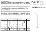
Aurelia
Brand: Safavieh Lighting Pages: 2

SR2
Brand: RAB Lighting Pages: 4

Raiju
Brand: campgo Pages: 33

KF-1067
Brand: Onwa Pages: 35

C-HB-A-LB2-SCCT Series
Brand: C-LITE Pages: 9


