

INET-CBDEX-E/INET-CBDEX-P
Cameo
®
Keypads with infiNET EX
®
Technology
Installation & Operation Guide
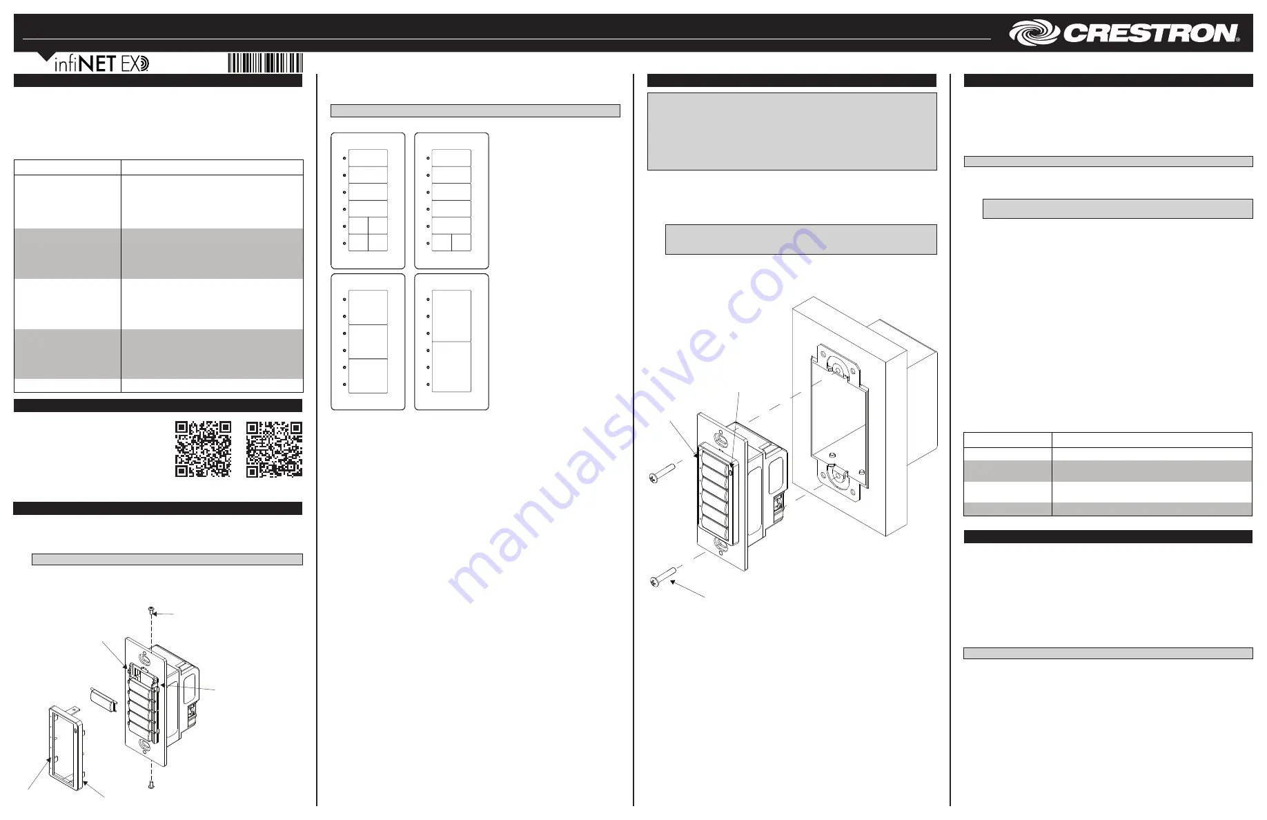
Assemble the Keypad
Attach the buttons to the keypad.
1. Arrange the button caps in position on the rear housing assembly according to the
program plan.
NOTE
: A single button cannot be installed in the lowest position of the keypad.
2. Carefully position the bezel over the button caps on the rear housing assembly and
secure with the two supplied #2-28 x 3/16 in screws.
3. Press and release each button to ensure that the button caps move freely.
Assemble the Keypad
Installation
NOTES
: Observe the following points.
• Install and use this product in accordance with appropriate electrical codes and
regulations.
• A licensed electrician should install this product.
NOTE
: Before using the INET-CBDEX, ensure the device is using the latest firmware.
Check for the latest firmware for the INET-CBDEX at www.crestron.com/firmware.
Firmware is loaded onto the device using Crestron Toolbox™ software.
Use the following procedure to install the keypad in a standard 1-gang electrical box.
1. Turn the ac power off.
2. Connect the ac power cable to the line, neutral, and ground terminals.
3. Holding the keypad with the LEDs on the left, place it in the electrical box.
4. Secure the keypad using the included #6-32 x 3/4 in screws.
CAUTION
: Excess wire pinched between the keypad and electrical box could
short-circuit. Make sure all excess wire is completely inside the electrical box and
not between the box and the keypad.
5. Make sure the keypad is oriented properly (note the location of the LED holes and
light sensor), place it in the electrical box, and attach using the supplied
6-32 x 3/4 in combo head screws.
Mounting the Keypad in a 1-Gang Electrical Box
Description
The INET-CBDEX-E and INET-CBDEX-P wireless Cameo keypads present a fresh,
innovative concept in keypad design. They offer cutting-edge wireless performance for
ease of installation, in a highly configurable 1-gang wall mount form factor that is at once
inviting to the touch and appealing to the eye.
The INET-CBDEX-E and INET-CBDEX-P are functionally identical. For simplicity within
this guide, the term “INET-CBDEX” is used except where noted.
Specifications
Additional Resources
Visit the product page on the Crestron website
(www.crestron.com) for additional information
and the latest firmware updates. Use a QR
reader application on your mobile device to
scan the QR image.
6. Attach the desired faceplate (not supplied).
7. Turn the ac power on.
INET-CBDEX-E
INET-CBDEX-P
Ambient Light Sensor Operation
The INET-CBDEX-P keypads have an ambient light sensor that can be used to
automatically configure the backlight to operate in either Day mode or Night mode.
Backlight operation is based on the ambient light level and a programmed threshold.
Presets based on the keypad color set the optimum backlight level for Day mode and
Night mode.
When presets are used, the following occurs:
• For light-colored keypads with dark engraving, the backlight turns on dim when in
Night mode and off when in Day mode.
• For dark-colored keypads, the backlight turns on dim when in Night mode and on
bright when in Day mode.
NOTE
: Backlight levels can also be set manually.
The indicator LEDs automatically adjust their brightness based on ambient light,
becoming bright when the keypad is well lit and becoming dim when the room is dark.
When two or more keypads are to be installed side by side, ensure that the backlights on
all units are in sync. For syncing to occur, there are signals available on the programming
symbol to allow one unit to act as the master backlight controller and the rest as slaves.
Refer to the help file for more information.
LED Hole(s)
Light Sensor
(INET-CBDEX-P Only)
Screw (2)
#6-32 x 7/8 in
Screw (2)
#2-28 x 3/16 in
LED Holes
LED Light
Pipes
Light Sensor
(INET-CBDEX-P Only)
Bezel
Wireless Communications
The device connects to the Crestron network via the infiNET EX communications
protocol. Use the procedures outlined below to join or leave an infiNET EX network and
to verify communications between the device and the control system.
Joining an infiNET EX Network
Before a device can be used in a lighting system, it must first join an infiNET EX network.
To join an infiNET EX network, the device must be acquired by an infiNET EX gateway.
NOTE
: A device can be acquired by only one gateway.
1. Put the infiNET EX gateway into Acquire mode from the unit itself or from Crestron
Toolbox™. Refer to the gateway’s manual at www.crestron.com/manuals for
details.
NOTE
: In an environment where multiple gateways are installed, only one
gateway should be in Acquire mode at any time.
2. Put the device into Acquire mode:
a. Tap the top button three times and then press and hold it down
(tap-tap-tap-press+hold) until the top LED on the device blinks once (this can
take up to 10 seconds).
b. Release the button to start the acquire process. The top LED blinks slowly to
show that the device is actively scanning the infiNET EX network.
• The top LED turns on for 5 seconds to show that the device has been
successfully acquired by the infiNET EX network.
• The top LED blinks fast to indicate that the device was not successfully
acquired by the infiNET EX network. Tap the top button to acknowledge the
failure. Ensure the gateway is in Acquire mode and within range before
attempting the acquire process again.
3. Once all devices have been acquired, take the gateway out of Acquire mode. Refer
to the gateway’s manual for details.
Leaving an infiNET EX Network
To leave an infiNET EX network, put the device into Acquire mode, as described in
“Joining an infiNET EX Network” above, when no gateway is in Acquire mode.
Verifying Communications Status
To check the communications status of the device, tap the top button three times and
then press and hold it down (tap-tap-tap-press+hold) for up to 2 seconds. The LED
blinks to indicate the communications status. Refer to the following table for details.
A variety of loose button caps are provided for the INET-CBDEX. The button
arrangements can be mixed and matched to suit the needs of the installation. The
following shows the basic arrangement of the buttons on the keypad.
NOTE
: Split small buttons may be installed in the bottom two positions only.
INET-CBDEX Keypad Button Arrangement
2
4
6
3
6
1
2
3
4
5
7
6
8
6
8
1
2
3
4
5
SPECIFICATION
DETAILS
Power Requirements (Line):
INET-CBDEX
120 volts ac, 50/60 Hz
INET-CBDEX-230
230 volts ac, 50/60 Hz
INET-CBDEX-277
277 volts ac, 50/60 Hz
Power Requirements (dc):
INET-CBDEX
60 volts dc
INET-CBDEX-230
60 volts dc
INET-CBDEX-277
60 volts dc
Environmental
Temperature
32° to 113° F (0° to 45° C)
Humidity
10% to 90% RH (noncondensing)
Heat Dissipation
1 Btu/h
Dimensions
Height
4.13 in (105 mm) without faceplate
Width
1.75 in (45 mm) without faceplate
Depth
1.87 in (48 mm)
Weight
3 oz (64 g)
LED
COMMUNICATIONS STATUS
Turns on for 5 seconds
The device is communicating with the control system.
Blinks three times
The device is communicating with the gateway, but the
gateway is not communicating with the control system.
Blinks twice
The device was previously joined to the network but is
not communicating with the gateway.
Blinks once
The device is not joined to the network.


