INSTALLATION INSTRUCTIONS
for MODEL IFW-64 SERIES RIGID STEM WARMERS
5925 Heisley Road • Mentor, OH 44060-1833
IFW 64 Series
FL-0314
Rev. 13 (05/06)
Page 1 of 2
Call Toll-free: 877-CRES COR (273-7267) • Fax: 800-822-0393 • www.crescor.com
ELECTRICAL SPECS:
VOLTS WATTS
AMPS
HERTZ PHASE
NEMA
120
250
2.0
60
1
5-15
240
275
1.1
60
1
6-15
Warmer should be installed by an experienced
electrician.
U.L. REQUIREMENTS:
A. Wires of warmers to be connected to 75°C wire.
B. Wires are to be installed in conduit.
C. Warmers are not to be installed any closer than 1” from
a wall.
D. Warmers must be
at least
16” above a combustible
surface.
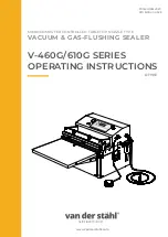
HOW TO INSTALL: (See fi gure at right)
NOTE: Item numbers are in parentheses.
Put the canopy (2) over the tube (4) and run the wire
through the threaded nipple of the canopy.
Connect the tube (4) to the canopy (2).
Remove two screws from the crown plate (3) and let
the canopy (2) slide down the tube (4).
Mount the strap (1) to the electrical outlet box with two
screws and nuts.
Wire the warmer leads to the outlet box with two
screws and nuts.
Attach the ground wires, one from the ceiling and the
one from the lamp, to the “GND” hole in the strap (1)
with the green screw.
Screw the canopy (2) to the crown plate (3) with the
two sheet metal screws.
Tighten all tubing connections; fasten threaded end
of bottom stem (5) into the socket assembly (6) and
tighten.
1.
2.
3.
4.
5.
6.
7.
8.
1
2
3
4
5
6