COP Security 15-WP16-USB, User Manual
The COP Security 15-WP16-USB is a reliable surveillance camera packaged with exceptional features. To uncover its full potential, make sure to download the comprehensive "User Manual" from our website. This manual is essential for understanding its functionalities and is available for "free" download. Visit manualshive.com to access your copy today!
Share
Download


Reviews:
No comments
Related manuals for 15-WP16-USB

TruVision DVR 10
Brand: GE Pages: 6

0E-4CHNVR2TB
Brand: W Box Pages: 67

X22A3N
Brand: Dahua Pages: 11

QSD9004CM
Brand: Q-See Pages: 6

X34A3L
Brand: Dahua Pages: 12

QSD2308C8
Brand: Q-See Pages: 5

TINF6
Brand: Infinite Play Pages: 8
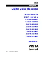
CADVR-1004-WD
Brand: Honeywell Pages: 63

H.264 HRDP
Brand: Honeywell Pages: 106
EVOLUTION 2
Brand: Honeywell Pages: 2

Fusion IV
Brand: Honeywell Pages: 150

FUSION III DVR
Brand: Honeywell Pages: 168

FUSION
Brand: Honeywell Pages: 168

HD-DVR-1004
Brand: Honeywell Pages: 182

HD-16DVR-C
Brand: Honeywell Pages: 169
HDVR
Brand: Honeywell Pages: 238

CADVR-04D
Brand: Honeywell Pages: 240

HRDV 16 Duplex
Brand: Honeywell Pages: 2


