Main Earthing Bar
Main Earthing Bar
TN
TT
*
*
*
**
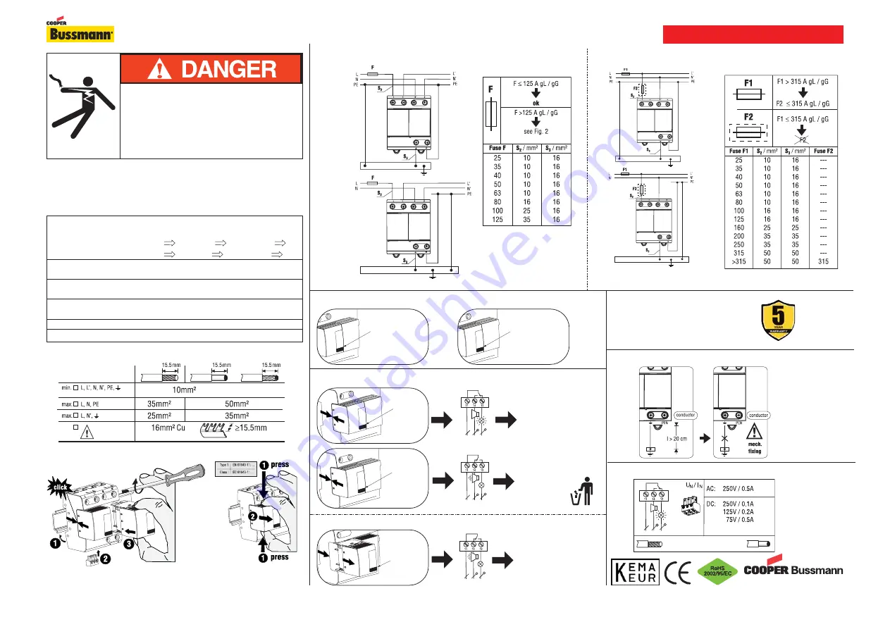
Hazardous Voltage
Will cause severe injury or death.
Working on or near energized circuits poses a
serious risk of electrical shock. De-energize all
circuits before installing or servicing this equipment
and follow all prescribed safety procedures.
Voltage Uc
255V/50Hz
Ifi
50kA rms
Iimp (10/350
μ
S)
TN
25kA (L
PE), 25kA (N
PE), 50kA (L+N
PE)
TT
25kA (L
N), 50kA (N
PE), 50kA (L+N
PE)
Max. Fuse
125A gL/gG - Series connection - Figure 1
315A gL/gG - Parallel connection - Figure 2
Types:
W/O Remote
BSPS2255TN
BSPS2255TT
With Remote
BSPS2255TNR
BSPS2255TTR
Replacement Modules
2X - BPS255IEC*
1X - BPS255IEC*
1X - BPS50NPEIEC**
Operating Temperature
-40°C to +80°C (+60°C Series connection - Fig. 1)
IP Rating
IP20
Conductors and Busbars for Use in IEC Systems
Torque to 7 N•m
Module Replacement
System Installation
Phillips Head Driver
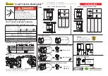
BSPS2255TN(R) & BSPS2255TT(R) Technical Data
IEC 61643-1 Type I, Two-Pole
TN & TT System Installation Instructions
3A1514 ©2010 Cooper Bussmann St. Louis, MO 63178
Publication No. 1542/US Update 12.10 ID-No. 062576
www.cooperbussmann.com
IEC APPLICATIONS
Mounting
Red
Green
Green
Green = Good
Red = Replace
Fault Indication & Remote Contact Signaling (with modules installed)
Testing Remote Contact Signaling (with modules removed)
Visual Indication Status
Green = Good
Red = Replace
Remove/Test
REMOTE OK
Main Earthing Bar
Main Earthing Bar
TN
TT
*
*
*
**
60/75°C max. 1.5mm
2
/14AWG
Remote Contact Signaling
Mechanical Fixing
Wiring
Surge Protection Made Simple
™
Fuse sizes are suitable for K=115 70°C
or higher rated cable
TN/TT Parallel conection
Fuse sizes are suitable for
K=115 70°C or higher rated
cable
Figure 1 - Series Connection & Fusing
Figure 2 - Parallel Connection & Fusing
Warranty
See document 3A1502 at
www.cooperbussmann.com/surge
for details of limited warranty.
This Product Is Obsolete
No recommended replacement is available


