Converteam ALSPA MV3DB Series, Manual
The Converteam ALSPA MV3DB Series user manual is available for free download from manualshive.com. This comprehensive manual provides detailed instructions and insights on operating and optimizing your ALSPA MV3DB Series product. Enhance your experience and maximize product efficiency by accessing the manual today.
Share
Download


Reviews:
No comments
Related manuals for ALSPA MV3DB Series

ePDU G3
Brand: Eaton Pages: 2

ePDU G3
Brand: Eaton Pages: 20

AF-600 FP Series
Brand: GE Pages: 129
Liebert NXC
Brand: Emerson Pages: 69

6502B
Brand: Symmetricom Pages: 24

COPIER GUARDIAN II
Brand: Smart power Pages: 2

DS4-8
Brand: Vdwall Pages: 8

USD
Brand: FEDERAL PIONEER Pages: 34

Sageon II 200A (N+1)
Brand: Unipower Pages: 131

VR 5000 noSpool
Brand: Fronius Pages: 132
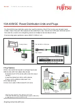
10A-400VDC
Brand: Fujitsu Pages: 2

RPM1581EV6
Brand: Minuteman Pages: 30

ALPU
Brand: Transtector Pages: 2

TSM4000H2
Brand: Tsubaki Pages: 28

Power Plant P300
Brand: PS Audio Pages: 9

Power Plant Premier
Brand: PS Audio Pages: 16

Humbuster III
Brand: PS Audio Pages: 16

Humbuster HBAC
Brand: PS Audio Pages: 16


