Contec EAD-CE-EC, User Manual
The Contec EAD-CE-EC is a versatile electronic device designed to simplify your everyday tasks. With this user-friendly product, you can easily operate various applications and systems. Access the free User Manual, available for download at manualshive.com, to fully explore its features and make the most out of this exceptional device.
Share
Download


Reviews:
No comments
Related manuals for EAD-CE-EC
LinkPro
Brand: ICON Pages: 6

PP7976
Brand: powerpack Pages: 9

DSM-232
Brand: G-cluster Pages: 2

WL-299 series
Brand: Gemtek Systems Pages: 20

13.500 A
Brand: brennenstuhl Pages: 91

10/100/1000 Base-T Ethernet PCI
Brand: IBM Pages: 38

TL-PA7010P
Brand: TP-Link Pages: 2
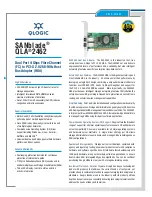
SANblade QLA 2462
Brand: Qlogic Pages: 2

NP285
Brand: NetComm Pages: 32

MISMATCH IS II BRAKE TO SRAM SHIFTER/DROPPER
Brand: Problem Solvers Pages: 8

CPSMM-120
Brand: Transition Networks Pages: 5

00049274
Brand: Hama Pages: 7

TD-W150KIT
Brand: TP-Link Pages: 47

PowerLife 3LR12PBXC
Brand: Philips Pages: 2

BKM-20D
Brand: Sony Pages: 2

BDV-HZ970W (UWA-BR100)
Brand: Sony Pages: 2

BDV-HZ970W (UWA-BR100)
Brand: Sony Pages: 2

AIR-SA10
Brand: Sony Pages: 1


