Congatec COM Express conga-IT6/COMe, User Manual
The Congatec COM Express conga-IT6/COMe is a powerful embedded computing solution for industrial applications. Users can easily access the user manual for this product for free by downloading it from manualshive.com. Get detailed instructions and specifications to optimize performance and functionality.
Share
Download


Reviews:
No comments
Related manuals for COM Express conga-IT6/COMe
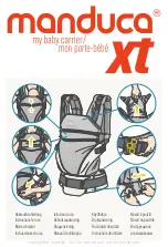
XT
Brand: manduca Pages: 20

DOONA
Brand: SimpleParenting Pages: 68

BABY CARRIER MOVE
Brand: BabyBjorn Pages: 136

NVIDIA Jetson TX2
Brand: Connect Tech Pages: 34

FLOWCLICK BABY SIZE
Brand: Fidella Pages: 2

Fashion
Brand: teutonia Pages: 32

travel cot
Brand: Lionelo Pages: 12

Caboo
Brand: Close Parent Pages: 9

Caboo dx+
Brand: Close Parent Pages: 16

Caboo +cotton blend
Brand: Close Pages: 58

05064698800070 - You And Me Infant Carrier
Brand: Chicco Pages: 64


