background image

INSTALLATION AND OPERATION MANUAL


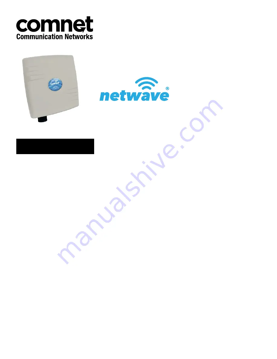
MINI INDUSTRIAL OUTDOOR 802.11A/N WIRELESS ETHERNET

Thank you for purchasing NetWave® from ComNet. This installation guide applies to 
the following models:

NW1/M: Industrial Multipoint, FCC Version, User Configurable

NW2/M: Industrial Multipoint, ETSI Version, User Configurable

NWK1/M:  Industrial Multipoint Kit, FCC Version (Includes NWK1/M_AP and 

NWK1/M_CL)

NWK2/M:  Industrial Multipoint Kit, ETSI Version (Includes NWK2/M_AP and 

NWK2/M_CL)

The NetWave industrially hardened wireless Ethernet transmission link from ComNet 
can be configured through the embedded User Interface as a Client or as an Access 
Point. This point-to-multipoint model allows multiple Ethernet endpoints to be 
connected to a central Access Point. Up to 15 endpoints can be linked to a central 
access point. The NW1/M and NW2/M support up to 95Mbps throughput using 
MIMO technology. An easy to read LED array displays unit operational status along 
with received signal strength ensuring optimal installation and operation. The units 
are passive powered by PoE (Power over Ethernet) through a supplied PoE injection 
module. The NW1/M is FCC certified and the NW2/M is ETSI, DFS and TPC certified.

This manual serves the following 

ComNet Model Numbers:

NW1/M
NW2/M
NWK1/M
NWK2/M

Summary of Contents for NetWave NW1/M

Page 1: ...nk from ComNet can be configured through the embedded User Interface as a Client or as an Access Point This point to multipoint model allows multiple Ethernet endpoints to be connected to a central Access Point Up to 15 endpoints can be linked to a central access point The NW1 M and NW2 M support up to 95Mbps throughput using MIMO technology An easy to read LED array displays unit operational stat...

Page 2: ...ines Knowledge of Local Area Network technology Related Documentation The following documentation is also available NW 1 2 M Datasheet NW 1 2 M Quick Start Guideº NWK 1 2 M Datasheet NWK 1 2 M Quick Start Guideº Website For information on ComNet s entire product line please visit the ComNet website at http www comnet net Support For any questions or technical assistance please contact your sales p...

Page 3: ...irements 9 5 0 Hardware Installation 9 5 1 Outdoor Ethernet Gland Installation 9 5 2 NW1 M and NW2 M Indicating LED Details 11 5 3 Outdoor Standard Mounting Hardware 11 5 4 Outdoor Upgrade Mounting Hardware 12 6 0 Key Default Configurations 13 7 0 Quick Configuration 14 Detailed Configuration 15 8 0 Getting Started 15 8 1 Operating Modes 16 8 2 Buttons and Alerts 16 9 0 Status Tab 18 9 1 Overview ...

Page 4: ...ration 30 10 4 Services 32 10 5 SNMP 33 10 6 Reset Button 34 10 7 Indicating LEDs 35 10 8 Backup Flash Firmware 36 10 9 Reboot 36 11 0 Network Tab 37 11 1 Interfaces WAN 38 11 2 Interfaces LAN 41 11 3 WiFi Overview 44 11 4 WiFi Wireless Network 48 11 5 Hostnames 58 11 6 Static Routes 58 11 7 Firewall 59 11 8 Diagnostics 61 11 9 Quality of Service 62 12 0 AP Controller Tab 63 12 1 Getting Started w...

Page 5: ...ATION AND OPERATION MANUAL NW 1 2 M TECH SUPPORT 1 888 678 9427 13 0 Troubleshooting 65 13 1 Troubleshooting steps 65 13 2 Resetting to factory default 65 14 0 Glossary 66 15 0 Agency Compliance 69 16 0 GPL General Public License Statement 71 ...

Page 6: ... electronic and mechanical for any purpose without the express written permission of ComNet Copyright Copyright 2015 Communication Networks LLC dba ComNet All rights reserved Disclaimer ComNet reserves the right to make changes in specifications at any time without notice The information furnished by ComNet in this material is believed to be accurate and reliable However ComNet assumes no responsi...

Page 7: ...0 1 x wireless drivers NetWave now includes a new user friendly LuCI web interface for configuring the device OpenWRT is an extensible GNU Linux distribution for embedded devices It is built from the ground up to be a full featured easily modifiable operating system It is powered by a Linux kernel that s more recent than most other distributions LuCI is a free clean extensible and easily maintaina...

Page 8: ...antenna support Preconfigured NWK kits do not support point to multipoint topologies PC NVR ComNet Gigabit Managed Switch with 30W PoE NW1 M IA870 Recommended Access Point PoE WIRELESS CAT5 POWER ETHERNET DATA LEGEND 10 100 Ethernet NW1 M Client PoE PIM or other PSE device Power IP Camera Ethernet Ethernet NW1 M Client PoE PIM or other PSE device Power IP Camera Ethernet Ethernet NW1 M Client PoE ...

Page 9: ...llation There will be at least one cable gland included with each outdoor enclosure Below is an image of the individual parts of the gland with an Ethernet cable routed through Note The split rubber washer allows a pre terminated Ethernet cable to be used Once the cable has been routed through the weather connection and the RJ45 connection has been made screw in the gland into the housing making s...

Page 10: ... 48 VDC A Connect one end of an RJ 45 Ethernet cable to the OUT port of the Power Injection Module PIM and the other end to LAN of the access point Maximum length of the RJ 45 CAT5 cable is 100 meters B Connect the RJ 45 Ethernet cable attached to the PIM to a network device such as to a switch or to the PC you will use to configure the access point C Connect the power adaptor to the main electric...

Page 11: ...AN Connected OFF No Connectivity RSSI1 SOLID RED Weak Connection RSSI2 SOLID ORANGE Moderate Connection RSSI3 SOLID GREEN Solid Connection RSSI4 SOLID GREEN Excellent Connection Advisable to check Status Page to confirm RSSI is 55 SIGNAL STRENGTH RSSI1 POWER RSSI2 LAN RSSI3 RSSI4 5 3 Outdoor Standard Mounting Hardware This mounting hardware will support pole diameters up to 2 in 5 8 cm Below are t...

Page 12: ...192 168 10 101 for all others LAN Mode for Web Server Static Addressing Web Server User ID admin Web Server Password admin SSID NetWave 1 WPA Pre shared Key 12345678 Channel Frequency AP Auto Channel Spectrum Width 20 40M Long Range Parameters Enabled and defaulted to 1000m Note A Reset to defaults performed on the ADMIN page or via the RESET button will erase all user configurations ...

Page 13: ... and set the desired network settings Select Apply Save Note This will be the network address for the NetWave web server It is not necessary to set to the same subnet as the operating network but it is recommended 8 Select the NETWORK WIFI tab and set Wireless mode Set to AP or Client Country code Only required if setting up the NW2 M ETSI model Note It is the user s responsibility to ensure that ...

Page 14: ...INS_NW 1 2 M_REV 06 10 13 PAGE 14 INSTALLATION AND OPERATION MANUAL NW 1 2 M TECH SUPPORT 1 888 678 9427 ...

Page 15: ... Next take the power adapter that comes with the set and connect it to a power socket as well as the router Turn on the power 3 Assign the Ethernet adapter on your computer with a static IP address on the 192 168 1 x network e g 192 168 10 10 and with a subnet mask 255 255 255 0 4 Launch a web browser and enter the default IP address of the router 192 168 10 101 into the address bar The first page...

Page 16: ...ras laptops or even other routers The stations obtain internet connection from the access point An access point WDS and a station WDS together extend the wireless coverage like a repeater 8 2 Buttons and Alerts The buttons are described here Reset Undo the changes Save Saves the changes but does not take effect till settings are applied Save Apply Saves and applies the changes Please use this butt...

Page 17: ...ease refer to Section Reset Button 8 2 2 Indicating LEDs The light emitting diodes LEDs on the board are described in Section LEDs on the Board 8 2 3 Buzzer The new NetWave buzzer makes the following sounds Power up Beep once End of Firmware Loading Beep twice Alignment Beep according to signal thresholds defined The alignment buzzer is described in Section Link Status for Station Mode ...

Page 18: ...see the second level tabs of Overview Routes System Log Kernel Log and Real time Graphs This is shown in Figure 2 Figure 2 The Status Tab 9 1 Overview The Status Overview page is divided into the sections Wireless Associated Stations System Memory Network and DHCP Leases Uptime Displays the duration of time since the router was turned on or rebooted Figure 3 The Status Overview page ...

Page 19: ...mmary of the wireless parameters The following describes the parameters when the device is in the AP mode Figure 5 A summary in the Wireless section for a device operating as an 802 11 access point SSID Displays the name of the wireless network that this access point AP is offering the Service Set Identifier SSID Mode This is Master if the device is in AP WDS mode Channel Shows the channel number ...

Page 20: ...ation is using Normally it would automatically select the same channel as the AP Bitrate This is the maximum bitrate supported by the radio in the current configuration MAC Address States the MAC address of the device s radio BSSID This is the MAC address of the AP s radio Encryption Displays the wireless encryption used ACK Timeout Shows the maximum acknowledgment time in microseconds DFS Status ...

Page 21: ...ss of the station as seen by the Radio Signal Displays the received signal strength from the station e g 31 dBm Signal Chains Shows the received signal strengths from the station on each antenna e g 52 35 34 dBm The value of 95 dBm is taken to mean no antenna if the radio has only 2 antennas Noise Displays the received noise power at the AP TX Rate Shows the transmit bit rate from the AP towards t...

Page 22: ...ses of connected computers with static DHCP leases They are specified in the Network Interfaces LAN Static Leases section of the device s configuration web page Figure 11 Currently active static DHCP leases 9 10 Link Status for Station Mode This section only applies if the device operates as an 802 11 station Figure 12 The Link Status section In the Link Status section on the Status Overview web p...

Page 23: ...hted Signal strength indicator LEDs See Section LED Configuration Just like for the LEDs more beeps indicate a higher received signal strength This is useful for a person aligning directional antennas at a height in an outdoor scenario if the LEDs are not visible Another person on the ground could adjust the threshold values for the LEDs There is some delay before the received signal strength gets...

Page 24: ...L NW 1 2 M TECH SUPPORT 1 888 678 9427 9 12 Kernel Log This page shows the kernel debugging messages This kernel log can also be obtained by typing dmesg in a serial console such as Tera Term if a suitable serial connector is used Figure 14 The Status Kernel Log page ...

Page 25: ...TALLATION AND OPERATION MANUAL NW 1 2 M TECH SUPPORT 1 888 678 9427 9 13 Real time Graphs Under the tab for Real time Graphs there are four tabs titled Load Traffic Wireless and Connection 9 13 1 Load Figure 15 The graph for Real time Load ...

Page 26: ...2 M_REV 06 10 13 PAGE 26 INSTALLATION AND OPERATION MANUAL NW 1 2 M TECH SUPPORT 1 888 678 9427 9 13 2 Traffic Figure 16 The graph for Real time Traffic 9 13 3 Wireless Figure 17 The graph for Real time Wireless ...

Page 27: ...INS_NW 1 2 M_REV 06 10 13 PAGE 27 INSTALLATION AND OPERATION MANUAL NW 1 2 M TECH SUPPORT 1 888 678 9427 9 13 4 Connection Figure 18 The graph for Real time Connections ...

Page 28: ...rmware and Reboot This can be seen in Figure 18 Figure 19 The System top level tab Within the System page you can configure the device parameters such as the hostname and time zone 10 1 System Properties Within the section on System Properties there are tabs corresponding to General Settings Logging and Language and Style General Settings Local Time Displays the local time according to the time zo...

Page 29: ...m log server port Log output level and Cron Log Level Language and Style Figure 21 Modifying the Language and Style Language and Style Lets you choose the language and design of the router s web pages 10 2 Time Synchronization Enable NTP client Obtains the date and time from specified Network Time Protocol NTP servers NTP server candidates These are the sources of the time information At least thr...

Page 30: ...ion Requires you to re enter the password 10 3 2 SSH Figure 24 SSH settings in the System Administration page SSH Allows you to access the router s Linux shell and file system using the Secure Shell protocol For example the programs PuTTY and WinSCP can be used Interface Lets the device listen on a given interface or all interfaces Port Specifies the listening port the default being 22 Password au...

Page 31: ...mmand telnet 192 168 10 101 or telnet 192 168 10 101 23 into a Command Prompt if using Windows or into a Terminal if using Linux or Mac OS X 10 3 4 Web Figure 26 The router s web server mode and port Web Server Mode This can be set to Hypertext Transfer Protocol HTTP or Hypertext Transfer Protocol Secure HTTPS For HTTPS if you see the warning The certificate is not trusted because it is self signe...

Page 32: ...terval Specifies the time between successive pings the default being 5 seconds Startup Delay Sets the time delay after the router finishes rebooting before running the Ping Watchdog the default being 60 seconds Failure Count to Reboot Specifies the number of failed pings before the router reboots automatically 10 4 2 Auto Reboot Figure 28 Auto Reboot settings in the System Services page Auto Reboo...

Page 33: ...e shown 10 5 2 SNMP Configuration General Settings Figure 29 General settings for SNMP Enable SNMP Enables SNMP SNMP V2c Read Password Sets the community string for read only access to the variables on the SNMP agent by the network management station NMS The NMS is the software which runs on the SNMP manager default public SNMP V2c Write Password Sets the community string for read write access by ...

Page 34: ...of the SNMP manager which receives the trap messages SNMP Trap Port Sets the port number 10 6 Reset Button The reset button is a physical hardware button on the AP hardware board Depending on how long the button is pressed you can reboot the board or reset it to factory default First make sure that the power is on and wait a minute for the board to finish starting up The following table shows the ...

Page 35: ...ed signal strength thresholds in dBm above which RSSI LEDs 1 to 4 would light up Figure 31 Signal strength indicator LEDs and their default threshold values in dBm 10 7 2 Summary of the LED Indicators WEAK SIGNAL EXCELLENT SIGNAL LED VISUAL CUE INDICATION POWER SOLID GREEN Power is supplied to the unit OFF No power is supplied to the unit LAN SOLID GREEN LAN Connected OFF No Connectivity RSSI1 SOL...

Page 36: ...d in clear text Reset to defaults Perform reset Resets the firmware to its initial state Restore backup Upload archive Lets you upload a previously generated backup archive to restore configuration files 10 8 2 Flash new firmware You can upload a new firmware to replace the currently running firmware Keep settings Retains the current configuration Firmware Shows the current version of the firmware...

Page 37: ...ay is a network point that acts as an entrance to another network Figure 32 The Network top level tab Figure 33 The Interface Overview on the Network Interfaces page The Network column shows that the WAN zone has the physical port eth1 as its interface In Figure 33 the LAN zone icon with two Ethernet ports has the bridged interface br lan which consists of one physical port icon with one Ethernet ...

Page 38: ... protocols are PPTP PPPoE and L2TP Protocol Static address IPv4 address Sets the IP address of the device as seen from the WAN zone IPv4 netmask Sets the subnet mask e g 255 255 255 0 The IP address and netmask together determine the subnet or network ID e g 192 168 10 0 24 Two devices must be in the same subnet in order to establish a Layer 2 link between them IPv4 gateway Specifies the IP addres...

Page 39: ...Sets the username for the Password Authentication Protocol PAP or the Challenge Handshake Authentication Protocol CHAP PAP CHAP password Sets the password for the PAP or CHAP Configure PPTP IP settings Upon clicking the Configure button the PPTP Common Configuration page would be displayed The protocol DHCP client or Static address can be selected The corresponding options are explained within thi...

Page 40: ... Unless your ISP requires it is not recommended to change this setting Use gateway metric Allows you to specify a gateway metric This acts as a cost for choosing the gateway when a connected device has to select between multiple available gateways The gateway with the smallest metric is chosen Use broadcast flag When sending DHCP requests a client can indicate if it wants an answer in unicast or b...

Page 41: ...4 address Sets the IP address of the device e g 192 168 10 1 where you can access the Radios configuration web page IPv4 netmask Sets the subnet mask e g 255 255 255 0 The IP address and netmask together determine the subnet or network ID e g 192 168 10 0 24 Two devices must be in the same subnet in order to establish a Layer 2 link between them IPv4 gateway Specifies the IP address of the remote ...

Page 42: ...u to specify a gateway metric This acts as a cost for choosing the gateway when a connected device has to select between multiple available gateways The gateway with the smallest metric is chosen Use broadcast flag When sending DHCP requests a client can indicate if it wants an answer in unicast or broadcast by setting the broadcast flag This is required for certain ISPs Unchecked by default Use d...

Page 43: ...esses for clients If disabled only clients having static leases will be served Checked by default Force Forces DHCP on this network even if another server is detected unchecked by default IPv4 Netmask Overrides the netmask sent to clients Normally it is calculated from the subnet that is served DHCP Options Defines additional DHCP options for example 6 192 168 10 1 192 168 10 2 which advertises di...

Page 44: ...reless local area networks WLANs are displayed under each radio Figure 36 The Wireless Overview page showing one radio Spectrum Shows the Channel Scan Report and allows you to run the Interference Analyzer Add Allows you to add virtual access points VAPs to the radio By default there is only one VAP on the radio Each VAP corresponds to one network Enable Enables the radio Disable Disables the radi...

Page 45: ...dio is operating as an AP the section for Associated Stations shows a list of stations connected to this device Figure 37 The Associated Stations are also shown on the Wireless Overview page The MAC address network name received signal strength noise power transmit rate receive rate and transmission quality for each station are displayed ...

Page 46: ...hannel Load Min RSSI Shows the minimum received signal strength indicator due to the neighboring access points Max RSSI Shows the maximum received signal strength indicator due to the neighboring access points Noise Floor Shows the level of the noise on the channel Channel Load Shows how much the channel is utilized A lower channel load denotes a channel with less interference You can click Radio ...

Page 47: ...eneral Setup Mode option after clicking on the Edit button Figure 39 The Wireless Overview page showing a radio as a Client station The following buttons are for a radio operating as a station Scan Scans for available wireless networks This button is available if the device is operating as a Station You can then select the network to connect to Join Network Associates this device with the selected...

Page 48: ...e Configuration section covers the physical settings of the radio hardware such as channel transmit power or antenna selection These are shared among all defined wireless networks of the radio Per network settings like encryption or operation mode are grouped in the Interface Configuration 11 4 1 Device Configuration The Device Configuration section consists of the section tabs for General Setup a...

Page 49: ... Chooses the frequency channel The default setting of Auto is may be used For an AP it would select the channel with the least interference from other APs For a station it would automatically select the same channel as its AP The frequency channel may also be manually selected An AP and its station must have the same channel in order to communicate Antenna Gain dBi Represents the gain relative to ...

Page 50: ...ion is illustrated with the following examples Example Country Code CZ Channel 100 Antenna Gain is 5dBi Transmit Power is 15dBm In the Czech Republic Channel 100 would mean the maximum power is 30dBm for EIRP Transmit Power is 15dBm when adding Antenna Gain of 5dBi it would be 20dBi which would NOT EXCEED the EIRP Thus the Max transmit power of the card is 15dBm as Antenna Gain has no effect ...

Page 51: ...P in ms A beacon is a frame broadcast by the AP to synchronize the wireless network For the multiple VAP case the beacons are transmitted evenly within this interval Thus if four VAPs are created and the beacon interval is 200 ms a beacon will be transmitted from the radio portion every 50 ms from each VAP in a round robin fashion The default value of the interval is 100 ms Adaptive noise immunity...

Page 52: ... name of the network as advertised in the beacon message In Station mode it is the network name that the station associates with BSSID Sets the MAC address of the AP This option is available for a device operating as a station This is useful because there can be multiple APs with the same ESSID Setting the MAC address would prevent the station from roaming to other APs Guard Interval Chooses betwe...

Page 53: ...ote WDS Mode is enabled by default Wireless Security Figure 43 Setting the Wireless Security for the Wifi Interface Encryption Chooses between No Encryption open and the following encryptions WPA PSK WPA2 PSK WPAPSK WPA2 PSK Mixed Mode WPA EAP and WPA2 EAP WPA or WPA2 with PSK Wifi protected access WPA is a stronger encryption than WEP Furthermore WPA2 was developed to strengthen the security of W...

Page 54: ...ion server Note Remote Authentication Dial In User Service RADIUS is a networking protocol that provides centralized Authentication Authorization and Accounting AAA management for users that connect and use a network service Radius Authentication Port Sets the port number for the RADIUS authentication server Normally the port number is 1812 Radius Authentication Secret Configures the password for ...

Page 55: ...y that issues digital certificates In a public key infrastructure scheme a digital certificate certifies the ownership of a public key by the named subject of the certificate Path to Client Certificate Selects the file for the client certificate Options for TLS as the EAP method Path to Private Key Selects the file for the private key Password of Private Key Configures the password for the private...

Page 56: ...b is only available for a device operating as an AP Figure 46 Configuring the MAC Filter for a Wifi AP MAC Address Filter Lets you allow only devices with the listed MAC address to associate with this AP or lets you block devices with the listed MAC address MAC List Adds the MAC address of the remote device to either block or allow ...

Page 57: ...P When Station Isolation is enabled the AP blocks communication between wireless clients on the same AP Maximum Stations Specifies the maximum number of associated stations the default being 127 Minimum Stations RSSI Sets the minimum received signal strength indicator for a station to be associated The default value of 0 means that the AP would allow a station to associate independent of its RSSI ...

Page 58: ...ctive IP addresses This is an additional local DNS Note The computers in the same subnet need to set the IP address of this device as their preferred DNS server in order to interpret these custom hostnames 11 6 Static Routes The Network Static Routes page shows the static IPv4 routes Figure 48 Static IPv4 Routes Each row shows the interface and gateway over which a certain host or network can be r...

Page 59: ...settings Zone Settings Figure 49 General Settings for the Firewall Zones Enable SYN flood protection Checked by default Drop invalid packets Unchecked by default Input To accept by default Output To accept by default Forward To reject by default Zones Figure 50 The Zones section showing the default settings for the firewall zones 11 7 2 Port Forwards Port forwarding allows remote computers on the ...

Page 60: ...all Traffic Rules page configures the traffic rules and source NAT Traffic Rules Traffic rules define policies for packets travelling between different zones for example to reject traffic between certain hosts or to open WAN ports on the router Figure 52 Firewall Traffic Rules with the default settings Figure 53 You can choose to open ports on the router or add new forwarding rules ...

Page 61: ...ing which allows fine grained control over the source IP used for outgoing traffic for example to map multiple WAN addresses to internal subnets Figure 54 Source NAT 11 8 Diagnostics 11 8 1 Network Utilities Figure 55 Network Utilities consist of Ping Traceroute and Nslookup Figure 56 Result of Ping Figure 57 Result of Traceroute Figure 58 Result of Nslookup ...

Page 62: ...RT 1 888 678 9427 11 9 Quality of Service The Network QoS page configures the quality of service QoS With QoS you can prioritize network traffic that passes through the WAN port You can limit the download and upload speeds Network QoS is disabled by default Figure 59 Network QoS settings ...

Page 63: ...rowser Click on the network tab to check that the L2TP is communicating packets with the APc 3 Set the hostname of the AP to better identify it The following describes the APController top level tab When using the APc for the first time you only need to set the IP address of the APc This has to be done in the AP s configuration web page itself All other settings should remain as the default values...

Page 64: ...a insertion Pre shared key Sets the password for the IPsec 12 4 APc SNMP Settings The SNMPv3 AP to APC section contains the APc SNMP settings Figure 60 APc SNMP Settings Currently the following default values must be used User Name admin Auth Password apc0ntr0ll3r Privacy Password apc0ntr0ll3r 12 5 AP SNMP Settings For communication from the APc to the AP the settings in the following section of t...

Page 65: ...P addresses must be unique and be of the form 192 168 3 X Check whether the router and your computer are connected on the same network by running the ping command to ping the IP address of the router Alternatively type the following in the router s Linux terminal ping 192 168 3 77 if your computer s IP address is 192 168 3 77 for example They should be able to give the ping responses An IP address...

Page 66: ...rchical naming system for computers services or any resource connected to the Internet or a private network EIRP Equivalent Isotropically Radiated Power Each country sets the legally permitted maximum for the EIRP limits on each channel ESSID Extended Service Set Identifier This is the name of the wireless network It is case sensitive and up to 32 alphanumeric characters in length The ESSID differ...

Page 67: ...necting a network of hosts to an ISP without the ISP having to manage the allocation of IP addresses PPTP Point to Point Tunneling Protocol This is a protocol for the creation of VPNs for the secure transfer of data from remote clients to private servers over the Internet QoS Quality of Service This is the prioritization of network traffic Voice traffic gets the highest priority followed by video ...

Page 68: ...e Network This is a network that enables IP traffic to travel securely over a public TCP IP network by encrypting all traffic from one network to another The VPN uses tunneling to encrypt all information at the IP level WAN Wide Area Network This is a network that covers a broad area The world s most popular WAN is the Internet Web Browser A software that allows the user to surf the Internet WDS W...

Page 69: ...se the user will be required to correct the interference at his own expense Industry Canada This Class A digital apparatus complies with Canadian ICES 003 To reduce potential radio interference to other users the antenna type and its gain should be so chosen that the equivalent isotropically radiated power EIRP is not more than that permitted for successful communication This device complies with ...

Page 70: ...d Italy Netherlands Norway Portugal Romania Switzerland Sweden Installer Compliance Responsibility Devices must be professionally installed and it is the professional installer s responsibility to make sure the device is operated within local country regulatory requirements RoHS WEEE Compliance Statement European Directive 2002 96 EC requires that the equipment bearing this symbol on the product a...

Page 71: ... were granted a license to that software under the terms of either the GNU General Public License or GNU Lesser General Public License License copies of which are available from http www gnu org licenses licenses html The Licenses allow you to freely copy modify and redistribute that software without any other statement or documentation from us ComNet will provide to anyone who contacts us at the ...

Page 72: ...RLEY LEEDS UK LS27 7LE T 44 0 113 307 6400 F 44 0 113 253 7462 INFO EUROPE COMNET NET ComNet Customer Service Customer Care is ComNet Technology s global service center where our professional staff is ready to answer your questions at any time Email ComNet Global Service Center customercare comnet net Contact Information ComNet www comnet net North America ComNet Corporate Headquarters and Custome...

Reviews: