


INS_FVT/FVR80D8SFP_REV–
05/07/10
PAGE 1
INSTALLATION AND OPERATION MANUAL
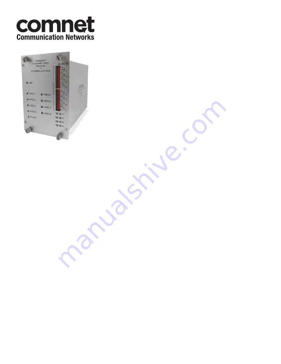
FVT/FVR80D8SFP
8-CHANNEL DIGITALLY ENCODED VIDEO
+ 8 CHANNELS OF BI-DIRECTIONAL DATA USING
SMALL FORM-FACTOR PLUGGABLE (SFP) OPTICAL DEVICES
The FVT/FVR80D8SFP series optical video link provides transmission of
eight 10-bit medium-haul quality digitally encoded video channels and eight
bi-directional data channels through a selectable small form factor pluggable
module (SFP). See instructions included with SFP for installation of selected
module.
Figure 5
on
Page 3
illustrates the data electrical connections from the RJ45 Data
connectors and also the connection cable and “breakout box” connections.
Figure 7
on
Page 5
illustrates the specific data connections for RS232, 2-Wire
RS485 and RS422/4-Wire RS485. (This last data connection also applies to
Manchester & Bi-Phase data transmission.)
Each data channel is configured for the electrical interface by means of the
“DATA SELECT” switch on the front panel.
Figure 6
on
Page 4
illustrates the
switch settings to set the type of data for each channel.
Figure 8
on
Page 6
illustrates the electrical connections between the
“Customer Equipment” and the FVT80D8SFP and FVR80D8SFP.
Bi-color (Red/Green) LED indicators are provided for confirming operating
status. See
Figure 4
on
Page 3
for LED indication explanations.
These units are interchangeable between stand-alone or card mount
configurations. See
Figure A
on
Page 7
for mounting instructions.


