COMAC ULTRA120 B, Use And Maintenance Manual
The COMAC ULTRA120 B is a high-performance industrial floor scrubber designed for heavy-duty cleaning tasks. Ensure optimal performance and longevity by following the instructions outlined in the comprehensive Use And Maintenance Manual. Download your free manual from manualshive.com to keep your machine running efficiently.
Share
Download


Reviews:
No comments
Related manuals for ULTRA120 B
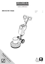
BDS 43/150 C Classic
Brand: Kärcher Pages: 12
B 40 C Bp
Brand: Kärcher Pages: 276
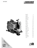
B 150 R
Brand: Kärcher Pages: 404

Hakomatic B 1050
Brand: HAKO Pages: 80

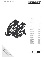
BD 70 W Classic Bp
Brand: Kärcher Pages: 280

D9
Brand: Dycon Pages: 44

FLOODKING
Brand: U.S. Products Pages: 24

TOPCLEAN 750VPRO+
Brand: ulsonix Pages: 270

HDS 13/20-4 S
Brand: Kärcher Pages: 272

25-X
Brand: lavina Pages: 33

SPRINTER il lavasciuga
Brand: Lavor Pages: 16

VST HP Series
Brand: Vortex Pages: 32

CARBON SPOT 55
Brand: Diamond Products Pages: 11

CROWN G20
Brand: Diamond Products Pages: 32

CO450.0
Brand: diversey Pages: 9

CO1650.1
Brand: diversey Pages: 59

CO2500
Brand: diversey Pages: 67

30105519-1313
Brand: Donaldson Pages: 16


