Dycon D9, Manual
Introducing the user-friendly "TEAM TEX D9" manual download, providing effortless access to the essential operating guidelines for your product. Enjoy the convenience of a free manual download from manualshive.com, ensuring a seamless experience. Get acquainted with your TEAM TEX D9 effortlessly, courtesy of our comprehensive user manual.
Share
Download


Reviews:
No comments
Related manuals for D9
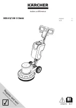
BDS 43/150 C Classic
Brand: Kärcher Pages: 12
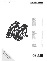
B 40 C Bp
Brand: Kärcher Pages: 276
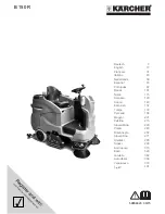
B 150 R
Brand: Kärcher Pages: 404

PATIO SCRUBBER PS46H
Brand: Fantom Pages: 4

TRG 720/200T
Brand: Numatic Pages: 28

EBB series
Brand: S&P Pages: 10

44-50
Brand: J&M Pages: 118

GT50 B50
Brand: GADLEE Pages: 2

FiberPRO 2.5 H
Brand: BETCO Pages: 12

Windsor Chariot 2 iScrub 20
Brand: Kärcher Pages: 167

110-R/D
Brand: Eureka Pages: 48

56104502
Brand: Nilfisk-Advance Pages: 132

FCE BULLDOG MINI
Brand: Jon-Don Pages: 59

BSCSCX264
Brand: Cutter Pages: 102


