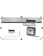
background image

1

ca5152. 2011 Audiovox Electronics Corporation. All rights reserved.

PROFESSIONAL

SERIES

Automatic / Manual Transmission

Remote Start with Keyless Entry

Installation Guide

ca 5152

Summary of Contents for ca 5152

Page 1: ...1 ca5152 2011Audiovox Electronics Corporation All rights reserved PROFESSIONAL SERIES Automatic Manual Transmission Remote Start with Keyless Entry Installation Guide ca 5152 ...

Page 2: ...ness 11 2 Pin Door Lock Harness 12 Additional Ports 16 Antenna LED Programming Port 16 DBI Port 16 Telematic Interface Port 16 Set Up Programming 17 Transmitter Programming 17 Manual Feature Programming 17 Programming Feature Banks 18 Tach Programming 20 Smart Tachless Mode 20 Feature Descriptions 21 Transmitter Button Functions 26 Remote Start Shutdown Diagnostics 27 System Layout 28 Table of Con...

Page 3: ... near hot surfaces Avoid mounting components or routing wires near moving parts Tape or loom wires under hood for protection and appearance Technical Support 800 421 3209 or go to http techservices codesystems com Use a Digital Multi Meter for testing and verifying circuits DO NOT USE A TEST LIGHT OR COMPUTER SAFE PROBE as these can set off air bags or damage vehicle computers Use grommets when ro...

Page 4: ...OR INPUT 4 BLACK WHITE ILLUMINATED ENTRY OUTPUT 5 BROWN BLACK HORN OUTPUT 6 RED WHITE TRUNK RELEASE OUTPUT 7 BLUE BLACK IGNITION 3 8 PURPLE WHITE TACH INPUT 9 GRAY HOOD PIN INPUT 10 BROWN RED BRAKE INPUT 11 VIOLET BLACK AUX 1 OUTPUT 11 PIN MAIN 1 PURPLE STARTER OUTPUT MOTOR SIDE 2 RED BATTERY 12V 3 ORANGE ACCESSORY 1 4 PINK WHITE IGNITION 2 5 RED WHITE BATTERY 12V 6 PINK IGNITION 1 6 PIN START ...

Page 5: ...d the interior light is off Connect the PURPLE wire to the vehicle s positive door input wire s NOTE Certain vehicles may require multiple connections Refer to vehicle application guide 1 GRAY RED PARKING BRAKE INPUT Locate the vehicle s parking brake wire Verification This wire will register ground when the vehicle s PARKING BRAKE is engaged NOTE The following connection is required for Manual Tr...

Page 6: ...icle s horn wire This is a low current output 500mA 6 RED WHITE TRUNK RELEASE OUTPUT Locate the vehicle s trunk release wire at the trunk release switch Verification This wire will register either positive voltage or ground when the trunk release is activated This is a low current output 500mA and is configurable in option programming 3 GREEN DOOR TRIGGER INPUT Locate the vehicle s dome light or d...

Page 7: ...or 3rd Accessory Wire Jump To ORANGE Accessory Output Wire From Control Module 7 BLUE BLACK IGNITION 3 ACTIVE OUTPUT The Active Output Ignition 3 output wire provides a ground output when the remote start function is activated and remains until 4 seconds after the remote start is shutdown The Ignition 3 output wire can be used for several functions listed below If this wire will be used for multip...

Page 8: ...8 PURPLE WHITE TACHINPUT Locate the vehicle s ignition coil or fuel injector in the engine compartment Verification Test using the following procedure 1 Set voltmeter to AC VOLTS 2 Attach positive lead of a volt meter to a constant 12 volt source 3 Attach negative lead of a volt meter to the wire to be tested 4 Start the engine 5 Have someone press on the gas pedal slightly as you monitor the mete...

Page 9: ...ACK wire with any other vehicle components 3 Pin Parking Light Harness 2 WHITE RED PARKINGLIGHTINPUT 3 WHITE PARKING LIGHTOUTPUT Locate the parking light output wire at the vehicle s light switch Verification This wire registers positive voltage when the parking lights are turned on Positive switching Parking Lights Connect the WHITE RED wire to a 15 Amp max fused battery source Connect the WHITE ...

Page 10: ...nt 12 Volt battery wire NOTE Remove all fuses until all connections are made 3 ORANGE ACCESSORY 1 Locate the vehicle s accessory wire at the ignition switch Verification This wire registers voltage when the key is turned to ACC Accessory and the ON or RUN position The voltage drops out when the key is turned to the START or CRANK position Connect the ORANGE wire to the vehicle s accessory wire 4 P...

Page 11: ...e constant 12 Volt battery wire NOTE Remove all fuses until all connections are made 4 Pin Alternate Harness 1 LT GREEN BLACK FACTORY DISARM PULSE BEFORE START This wire will supply a 500mA pulse both upon disarming the system and when the remote start feature is activated Locate the factory perimeter alarm disarm wire from the key cylinder inside the drivers door Verification This wire registers ...

Page 12: ...tarter Output Wire From The C ontrol Module 2 Pin Door Lock Harness 1 BLUE UNLOCK 2 GREEN LOCK The door lock unlock outputs are designed to control several different types of systems which may require additional parts Please review the wire and location chart to see which type of door lock system is in your vehicle The most common types are shown in the following diagrams 3 GREEN WHITE PULSE AFTER...

Page 13: ... Vehicle Door Lock Control Relays GREEN Lock Output BLUE Unlock Output Negative Locks Positive Switching Locks All Door Lock and Unlock Locate the lock unlock wire at the vehicle s lock unlock switch Verification These wires will register positive voltage when the Lock and Unlock switches are activated Connect the GREEN and BLUE wires shown in the diagram below Lock Unlock 87 87a 86 85 30 87 87a 8...

Page 14: ...used 12 Volt Battery Souce GREEN Lock Output BLUE Unlock Output Reverse Polarity Locks X Cut X Cut To Door Lock Motor To Door Lock Motor Negative Multiplexed Locks All Door Lock and Unlock Locate the lock unlock wire at the vehicle s lock unlock switch Verification This wire will show variable ground when the switch is activated Please consult the wire and location chart for specific resistor valu...

Page 15: ...UE GREEN wires shown in the diagram below using 2 SPDT relays not supplied Lock Unlock Vehicle Door Lock Control Relays GREEN Lock Output BLUE Unlock Output Multiplex Locks 87 87a 86 30 87 87a 86 30 85 85 Fused 12 Volt Battery Source Resistor Adding Aftermarket Actuators After installing aftermarket actuators not supplied Connect the GREEN and BLUE wires shown in the diagram below using 2 SPDT rel...

Page 16: ...rvision Transponder Interface Activation Factory Alarm Arm Disarm Manual Arm Disarm Inputs factory keyless controls system Antenna LED Programming Port Mount the supplied antenna receiver to a clear spot on the vehicle s windshield that will not block the driver s vision A good location is usually high on the windshield near the rear view mirror Be careful not to mount the antenna receiver on any ...

Page 17: ...TE The system will remain in feature programming mode as long as the ignition is on there is no time limit To exit programming turn the IGNITION OFF Set Up Programming Transmitter Programming Feature Bank 1 1 Turn the ignition ON 2 Press and hold the valet override button 3 Within 10 seconds the system will chirp 3 three times 4 Press 1 button of each transmitter you wish to program 5 The system w...

Page 18: ...e Unlock Double Pulse Lock 1 Second Unlock Factory Disarm Lt Green Black Factory Disarm 2nd Unlock Factory Disarm Start Status 3 Ignition Controlled Locks OFF Lock and Unlock Lock Only Unlock Only 4 Trunk Output Timing Red White Output 1 Second Pulse 10 Seconds 20 Seconds Latched until IGN ON Latched ON until Button Press 5 Horn Output Timing 16mS 10mS 30mS 40mS 50mS 6 Real Panic ON OFF 7 AUX 1 Vi...

Page 19: ...s made in Bank 3 1 NOTE On this model the Lt Green Black Output wire can be configured in Bank 3 or Bank 5 Any changes to this feature in Bank 5 will override changes made in Bank 3 Feature Bank 4 6 Chirps Remote Start Control 1 LED Flash 2 LED Flash 3 LED Flash 4 LED Flash 5 LED Flash 6 LED Flash 1 RF Start Chirp ON OFF 2 Run Time 15 Minutes 5 Minutes 10 Minutes 20 Minutes 45 Minutes 60 Minutes 3...

Page 20: ...n the unit senses the tach signal the parking lights will begin to flash 6 Allow the vehicle to settle to a normal idle speed 7 Release the valet program push button switch The parking lights will turn on for 2 seconds indicating that the learned tach signal is stored and the unit has exited tach learn mode NOTE If the unit fails to learn tach rate due to an improper tach connection or a poor tach...

Page 21: ...le 1 second unlock pulse 3 5 Seconds Single 3 5 second lock pulse single 3 5 second unlock pulse 1 Second Lock Double Pulse Unlock Single 1 second lock pulse double 1 second unlock pulse 30 Second Lock Double Pulse Unlock Single 30 second lock pulse double 1 second unlock pulse Double Pulse Lock 1 Second Unlock Double 1 second lock pulse single 1 second unlock pulse 2 Factory Disarm Controls the t...

Page 22: ...s output until the activation button is pressed again 5 Horn Output Timing Control the minimum horn pulse time in milli seconds some vehicle will require a longer pulse to activate the factory horn 16mS 10mS 30mS 40mS 50mS 6 Real Panic Controls the panic out when triggered from the transmitter ON Randomized horn honks when panic is triggered OFF Standard pattern horn honks when panic is triggered ...

Page 23: ...tly to the tach wire of the vehicle to monitor AC voltage Tachless Crank Average Voltage Determines crank time by averaging the last 8 times the vehicle was started with the key and then monitors the change in voltage after remote start Hybrid Crank Average No Voltage Determines crank time by averaging the last 8 times the vehicle was started with the key DBI Port Monitors the vehicle s tach rate ...

Page 24: ...t wire for 20 seconds after the ignition has been powered up by the remote start 45 Second Delay Diesel engine delays the starter output wire for 45 seconds after the ignition has been powered up by the remote start 9 Single Double Pulse Start Switches the remote start activation between a single or double press from the transmitter 10 IGN 2 Output Programmable high current output Ignition 2 Ignit...

Page 25: ...nce and has confirmed the vehicle is running Also a 1 second pulse when unlock is pressed Ground While Running Continuous output for the entire remote start sequence until after the vehicle shuts down Ignition Output becomes active with the same timing as the ignition output and does not drop out during crank Accessory Output becomes active with the same timing as the accessory output drops out du...

Page 26: ...utput and does not drop out during crank Accessory Output becomes active with the same timing as the accessory output drops out during crank 1 Way Transmitter Lock Unlock Car Find Panic Start Operation Method Lock X Press and Release Unlock X Press and Release Trunk X Push and Hold 3 Sec Car Finder X Press and Release Panic X Push and Hold 3 Sec Remote Start X Press and Release 1 or 2 times depend...

Page 27: ... of the patterns below indicating the shutdown input To manually enter diagnostics and view the last shutdown turn the ignition ON and press and release the button LED FLASHES SHUTDOWN ZONE 3 Flashes Hood Input Brake Input 4 Flashes Remote Start Valet Mode 5 Flashes Manual Transmission Mode not set manual transmission models only 7 Flashes Tach not learned Crank Average not learned ...

Page 28: ...RY 12V ORANGE ACCESSORY 1 PINK WHITE IGNITION 2 RED WHITE BATTERY 12V PINK IGNITION 1 BLACK GROUND WHITE RED PARKING LIGHT INPUT WHITE PARKING LIGHT OUTPUT GRAY RED PARKING BRAKE INPUT PURPLE DOOR INPUT GREEN DOOR INPUT BLACK WHITE ILLUMINATED ENTRY OUTPUT BROWN BLACK HORN OUTPUT RED WHITE TRUNK RELEASE OUTPUT BLUE BLACK IGNITION 3 ACTIVE OUTPUT PURPLE WHITE TACH INPUT GRAY HOOD INPUT BROWN RED BR...

Page 29: ...ules and with RSS 210 of Industry Canada Operation is subject to the following two conditions 1 This device may not cause harmful interference and 2 This device must accept any interference received including any interference that may cause undesired operation Warning Changes or modifications not expressly approved by the party responsible for compliance could void the user s authority to operate ...

Reviews: