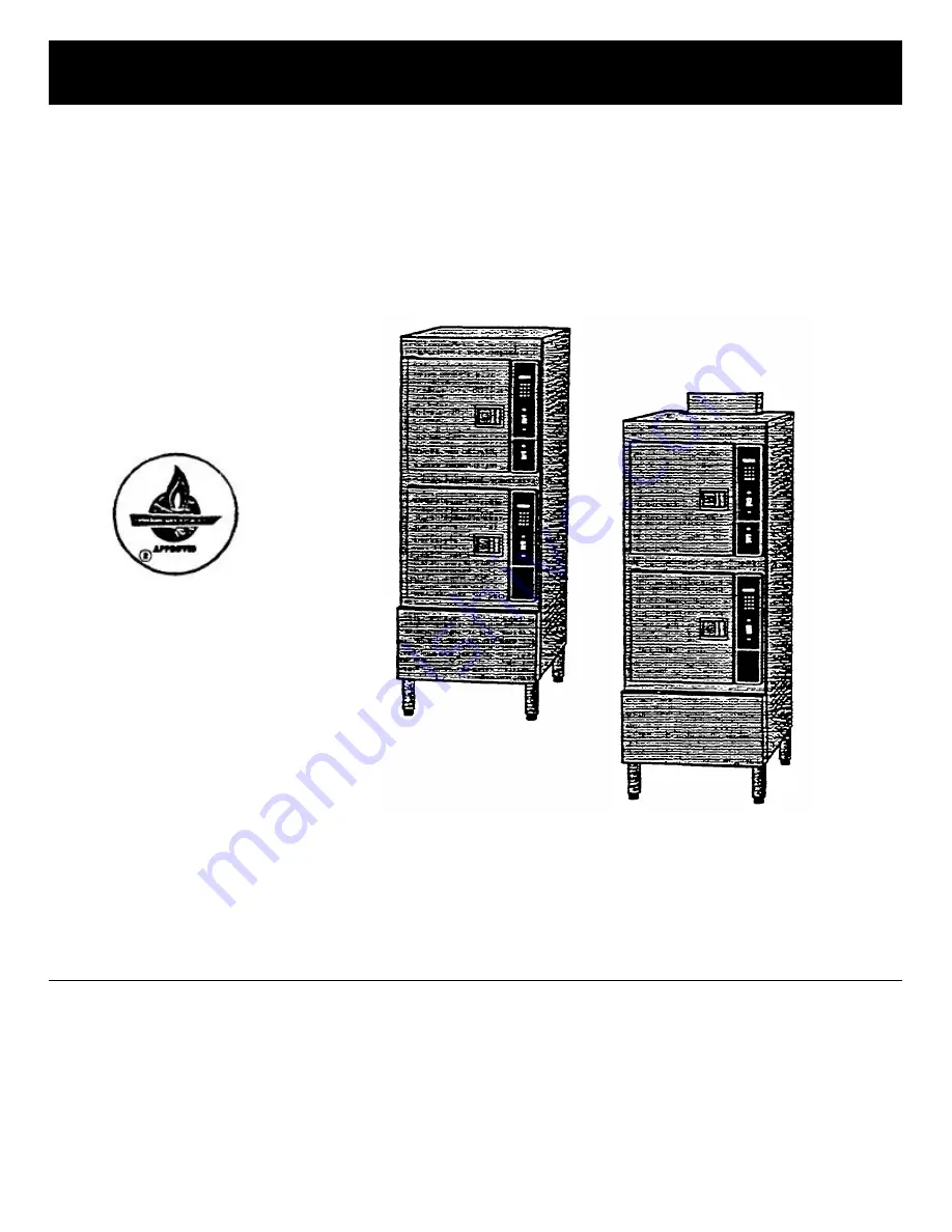
background image

Cleveland Range 

SteamCraft 10

®


Convection Steamer 


MODELS: 24-CEA-10, & 24-CGA-10 

Cleveland Range, Inc. 


SERVICE 

MANUAL 

Printed 3/93


UNITED STATES


1333 East 179th St.. Cleveland, Ohio 44110 Phone: (216) 451-4900 • 

Telex: 98-0546 • FAX: (216) 481-3782 

CANADA


Garland Commercial


Ranges 

1177 Kamato Road 
Mississaugha, Ontario. Canada L4W1X4 
Phone: (416) 624-0260 - FAX: (416) 624-0623 

Summary of Contents for 24-CEA-10

Page 1: ...10 Cleveland Range Inc SERVICE MANUAL Printed 3 93 UNITED STATES 1333 East 179th St Cleveland Ohio 44110 Phone 216 451 4900 Telex 98 0546 FAX 216 481 3782 CANADA Garland Commercial Ranges 1177 Kamato Road Mississaugha Ontario Canada L4W1X4 Phone 416 624 0260 FAX 416 624 0623 ...

Page 2: ... warranty coverage This table is not a comprehensive list of the owner user s responsibilities Cleveland Range steam products are intended for use only by professionally trained personnel To meet his responsibilities the owner user must supplement this guide with any additional actions consistent with the operation of steam generating food preparation equipment by a trained professional Warranty P...

Page 3: ...UCTIONS 18 Unpacking Inspection 18 Shipping Damage Instructions 19 Position Level The SteamCraft 10 19 Adjustable Leveling Legs 19 Positioning Leveling 19 Install Slide Racks 20 Install Connect The Free Air Vented Drain Lines 20 Exhaust Hood Ventilation All Models 22 Install Electric Power Lines 22 Connect Electrical Line 23 Install Water Supply Lines 24 Connect Water Supply Lines 26 General Conne...

Page 4: ...3 Manual Operation 43 Timed Operation 43 Manual Timer 43 Steam Generator BlowDown 44 MAIN DISCONNECT SWITCH 44 CONTROL PANELS 44 COOKING OPERATIONS KEY PAD CONTROL PANEL 46 Summary Of Cooking Operations 46 Power ON Automatic Fill 47 Start Steam Supply 47 Inspect The Cooking Compartment 47 Preheat The Cooking Compartments 48 Place Food Into The Cooking Compartment s 49 Select The Operating Mode 49 ...

Page 5: ...N 63 MAINTENANCE RECORDS 63 DAILY MAINTENANCE 63 Blowdown Steam Generator 63 Clean SteamCraft 10 63 WEEKLY MAINTENANCE 63 Clean Drain 63 MONTHLY MAINTENANCE 64 Descale Steam Generator 64 YEARLY MAINTENANCE 67 Clean Water Line Strainer 67 TROUBLESHOOTING NOTES 70 CHAPTER 5 COMPONENT AND CIRCUIT FUNCTIONS 71 INTRODUCTION 71 Models Covered In This Chapter 71 Figures and Illustrations 71 SteamCraft 10...

Page 6: ... Valves 87 Water Fill Solenoid Valves 87 Condenser Solenoid Valves 87 Preheat Thermostat 88 Key Pad and Dial Timers 88 Electronic Key Pad Timer 88 Compartment Thermostat Electronic Key Pad Units Only 89 Mechanical Timer 89 3 Second Timer And Buzzer Mechanical Timer Units Only 89 Heater Element Model 24 CEA 10 89 Dryer Element Model 24 CEA 10 89 High Temperature Limit Switch 89 Combustion Control M...

Page 7: ...DEL 24 CGA 10 98 Set Up the Initial Test Conditions 98 COMPONENT TEST PROCEDURES 123 Initial Conditions for All Testing 123 CT 1 Drain 3 Way Solenoid Valves 123 CT 2 3 Minute Timer 124 CT 3 Rinse Solenoid Valves 125 CT 4 Water Fill Solenoid Valves 126 CT 5 ON OFF Switch 127 CT 6 Float Assembly 128 CT 7 Gas Control Transformer 24 Volt Model 24 CGA 10 131 CT 8 Preheat Thermostat Steam Generator 131 ...

Page 8: ...urner Ignition Control System Components Model 24 CGA 10 147 CHAPTER 7 ILLUSTRATED PARTS LISTS 149 INTRODUCTION 149 Parts Differences Among SteamCraft 10 Steamers 149 Electrical Schematics And Wiring Diagrams 149 Ordering Parts 149 CHAPTER 8 IGNITION MODULE 199 INTRODUCTION 199 HONEYWELL WHITE RODGERS MANUALS 199 Printed 3 93 Cleveland Range Inc Models 24 CGA 10 and 24 CEA 10 Steam Craft 10 Servic...

Page 9: ...on SteamCraft 10 steamers Other than selection of options there are presently no significant design parts or operating differences among steamers with the same model number Figure 1 2 Sheets 1 through 4 illustrate the four SteamCraft 10 models and identify the major components SERIAL NUMBER During manufacture SteamCraft 10 s are assigned individual serial num bers A typical SteamCraft 10 serial nu...

Page 10: ...Page 2 Chapter 1 SteamCraft 10 Service Manual Models 24 CGA 10 24 CGP 10 24 CEA 10 24 CEP 10 Figure 1 1 SteamCraft 10 Product information Plates Printed 3 93 Cleveland Range Inc ...

Page 11: ...CGA 10 24 CGP 10 24 CEA 10 24 CEP 10 SteamCraft 10 Service Manual Chapter 1 Page 3 Figure 1 2 SteamCraft 10 Models 24 CGA 10 and 24 CEA 10 with Key Pad Control Panel Sheet 1 of 4 Cleveland Range Inc Printed 3 93 ...

Page 12: ... SteamCraft 10 Models 24 CGP 10 and 24 CEP 10 with Key Pad Control Panel Sheet 2 of 4 Printed 3 93 Cleveland Range Inc Chapter 1 SteamCraft 10 Service Manual Models 24 CGA 10 24 CGP 10 24 CEA 10 24 CEP 10 Page 4 ...

Page 13: ...Models 24 CGA 10 24 CGP 10 24 CEA 10 24 CEP 10 SteamCraft 10 Service Manual Chapter 1 Page 5 Figure 1 2 SteamCraft 10 Models 24 CGA 10 and 24 CEA 10 with Dial Timer Control Panel Sheet 3 of 4 ...

Page 14: ...Page 6 Chapter 1 SteamCraft 10 Service Manual Models 24 CGA 10 24 CGP 10 24 CEA 10 24 CEP 10 Figure 1 2 SteamCraft 10 Models 24 CGP 10 and 24 CEP 10 with Dial Timer Control Panel Sheet 4 of 4 ...

Page 15: ...and electricians or experienced food service equipment installers This guide must be used in conjunction with professional experience and a thorough understanding of the local state and national utility construction and sanitation codes the most prominent of which are listed in the Installation Policies section below Before starting installation the owner and the installer should read through this...

Page 16: ...awings Figure 2 2 show the required utility connection points dimensions and clearances for each of the SteamCraft 10 models Table 2 1 Installation Check List outlines the overall installation process by listing in recommended sequence the major tasks to be performed For each task the table references applicable notes from Figure 2 1 and the manual pages on which the task instructions begin Comple...

Page 17: ...he quality requirements of Table 2 2 and the pressure requirements on page 16 6 A SteamerGard filtering system is recommended when water quality does not meet the Table 2 2 requirements 7 Run a single water line between the main cold water supply and the tee The two separate steam generator and condenser blowdown supply lines are relatively short 8 A manual shut off valve must be installed between...

Page 18: ...lectric Power Requirements The characteristics of me electric power supply must match the power requirements specified on the SteamCraft 10 product identification plate The plate is located on the left side panel in the lower right comer as detailed in Figure 2 2 Gas Supply Requirements NEVER EXCEED 14 WATER COLUMN 1 2 psi GAS PRESSURE If the gas supply pressure exceeds 14 water column a pressure ...

Page 19: ...nts probes and solenoid valves Of equal importance is me decrease in heat transfer efficiency caused by lime and scale deposits Decreased heat transfer increases water and power consumption Use of the SteamCraft 10 in areas with poor water quality requires installation of a SteamerGard water treatment system or increased frequency of maintenance cleaning and descaling Check the quality of supply w...

Page 20: ...ge 12 Chapter 2 SteamCraft 10 Service Manual Models 24 CGA 10 24 CGP 10 24 CEA 10 24 CEP 10 Figure 2 2 SteamCraft 10 Dimensions and Clearances Model 24 CGA 10 Sheet 1 of 4 Printed 3 93 Cleveland Range Inc ...

Page 21: ...dels 24 CGA 10 24 CGP 10 24 CEA 10 24 CEP 10 SteamCraft 10 Service Manual Chapter 2 Page 13 Figure 2 2 SteamCrafi 10 Dimensions and Clearances Model 24 CGP 10 Sheet 2 of 4 Cleveland Range Inc Printed 3 93 ...

Page 22: ...ge 14 Chapter 2 SteamCraft 10 Service Manual Models 24 CGA 10 24 CGP 10 24 CEA 10 24 CEP 10 Figure 2 2 SteamCraft 10 Dimensions and Clearances Model 24 CEA 10 Sheet 3 of 4 Printed 3 93 Cleveland Range Inc ...

Page 23: ...dels 24 CGA 10 24 CGP 10 24 CEA 10 24 CEP 10 SteamCraft 10 Service Manual Chapter 2 Page 15 Figure 2 2 SteamCraft 10 Dimensions and Clearances Model 24 CEP 10 Sheet 4 of 4 Cleveland Range Inc Printed 3 93 ...

Page 24: ...y for assistance with chlorinated water Water Supply System Select a water supply system that fulfills the requirements listed in Table 2 2 The supply must provide a minimum dynamic pressure of 35 psi 2 4 kg cm2 and a maximum static pressure of 60 psi 4 1 kg cm2 Refer to page 24 for detailed pressure and fitting requirements and recommended plumbing layouts Always connect a cold water supply to th...

Page 25: ...mbustible locations as for combustible locations 5 The dimension drawings Figure 2 2 specify all dimensions and clearances required for proper operation and service of each SteamCraft 10 Steamer covered in this manual Maintain at least a 3 inch operating clearance at the sides of the unit and at least a 3 inch clearance at the back Do not store articles on top of the unit 6 The lower from and righ...

Page 26: ...rs damaged do not open the carton Refer to the Shipping Damage Instructions on page 19 If the shipping carton is undamaged proceed with step 2 2 Slit the four corners of the carton and peel carton sides away from the SteamCraft 10 The slide racks are shipped in separate packing inside the cooking compartment Be careful not to damage or throw these racks away 3 Remove the slide rack carton from the...

Page 27: ...y are completed While preparing the utility lines protect the SteamCraft 10 as described on page 10 After the lines are prepared position and level the SteamCraft 10 then connect the utility lines Adjustable Leveling Legs The supporting legs of the SteamCraft 10 Steamer are 6 inches long when the adjustable feet are fully retracted This provides the minimum 6 inch space below the unit required by ...

Page 28: ...other racks Install and Connect the Free Air Vented Drain Lines The drain outlet must be free air vented to equalize the pressure in the Steam Craft 10 Steamer with the atmosphere Generating steam causes pressure to increase in the unit cold water flow into the condenser creates a vacuum low pressure in the condenser Without a free air vent either high or low pressure in the compartment will cause...

Page 29: ...nder the body of the unit Steam rising from the drain up into the unit body will adversely affect operation cooling air ventilation and may cause corrosion on some of the electrical contacts Improper location of this drain will seriously reduce warranty coverage 3 The total length of pipe and number of bend fittings required to reach the open drain determines the pipe size used to extend the drain...

Page 30: ...an existing exhaust hood cannot be used a new one should be con structed over the SteamCraft 10 The Dimensions and Clearances Draw ing Figure 2 2 contains the dimensions gas flow and BTU per hour data required to calculate the minimum required hood dimensions and minimum ventilation capacity c f m Install Electric Power Lines Furnishing and installing the electrical power lines switches fuse boxes...

Page 31: ...r right corner as detailed in Figure 2 2 Table 2 3 Minimum Wire Requirements Use solid copper wire rated for 75 C wet location Connect Electrical Line VOLTS KILOWATTS AMPS 3 Phase SERVICE AMPS WIRE SIZE 208 32 6 92 115 0 220 27 4 73 91 1 240 32 6 80 100 1 440 27 4 36 45 6 480 32 6 40 50 6 Refer to Table 4 1 and identify the electrical schematic diagram that applies to the SteamCraft 10 model being...

Page 32: ...ing the steam generator and condenser blowdown water supply lines These fittings are detailed as C and B in Figure 2 2 2 Always connect a cold water supply to both water supply lines DO NOT USE HOT WATER The steamer will not function properly or within design safety limits if hot or warm water is supplied to either the condenser connection or the steam generator fill connection 3 Do not connect th...

Page 33: ...side the SteamCraft 10 The two separate lines from the tee to the steam generator and condenser blowdown connections are comparatively short b When installing a water supply system with a SteamerGard Cleveland Range recommends the plumbing layout illustrated in Figure 2 11 Note the following details This is a single water line from the main cold water supply to the tee just before the SteamerGard ...

Page 34: ...the recommended plumbing layouts Flush the water supply lines before connecting the strainer s If the remaining water supply lines and or SteamerGard are not immediately installed and connected after flushing temporarily cap the water supply lines If the final installation and connections are performed immediately refer to the connection instructions in the SteamerGard manual and Connect Water Sup...

Page 35: ...uld be installed between the tee and the steamer The steam generator line check valve should be installed between the SteamerGard and the steamer 3 Look at the flow indicating arrows on the strainers and check valves Verify that flow is toward the steamer 4 Install the connecting lines and flush them before connecting them to the water supply fittings on the steamer Be sure the line from the Steam...

Page 36: ...ion the drip leg should be close to the SteamCraft 10 gas connection 5 If natural gas pressure exceeds 14 water column a pressure regulating valve must be installed in the gas supply plumbing to reduce the pressure to within the limits specified in Gas Supply Requirements on page 10 6 If LP gas is supplied use a gas pipe joint compound which is resistant to LP gas Refer to Figure 2 2 and note the ...

Page 37: ...Check these connections for proper tightness 2 Prepare the Steam Craft 10 valves and connections for the test pressure being used The same pressure criteria apply when testing lines prior to the manual gas shut off valve The appliance and its individual shut off valve must be disconnected from the gas supply piping system during any pressure testing of that system at test pressures in excess of 14...

Page 38: ... following procedure 1 Turn off electrical power to the SteamCraft 10 at both the panel ON OFF switch Figure 2 16 and the main disconnect switch Figure 2 8 Rec ommended Electrical Layout 2 Remove the left side access panel by removing the three mounting screws Save the screws Verify that the automatic gas valve wiring connections are clean and tight Verify that the manual ON OFF valve of the autom...

Page 39: ...orm the Burner Ignition Tests next If the unit passes it is ready to resume normal cooking operations WARNING DO NOT TRY TO LIGHT THE BURNERS OR PILOT WITH A FLAME The SteamCraft 10 has an electronic ignition system which automatically lights the pilot and burn ers senses the flame and controls gas flow This provides precise burner control safety ignition and shutdown features DEATH INJURY OR EQUI...

Page 40: ...s of turning the unit ON the igniter controls are functioning End this test procedure here If the burners do not light within 9 minutes of turning the unit ON there may be air in the gas supply lines Proceed to step 5 4 For Pressure Models Only 24 CGP 10 and 24 CEP 10 Turn ON the electrical power to the SteamCraft 10 at the control panel ON OFF switch a The red indicator the switch lights and wate...

Page 41: ...ts and inspection of the SteamCraft 10 turn on all equipment drawing on the same utility supply lines Installation Checks Proper operation of the SteamCraft 10 is dependent upon proper installation Performing the following checks after installation could avoid unnecessary service calls 1 Refer to the appropriate dimension drawing and verify that the specified clearances are met 2 Verify that the u...

Page 42: ...amCraft 10 control panels have either a Key Pad Timer or a Dial Timer The operating difference between the Dial and Key Pad Control Panels is significant only in timed mode To avoid confusion a separate Timer Testing procedure is provided for the Dial and Key Pad Control Panels In addition SteamCraft 10 models 24 CGP 10 and 24 CEP 10 with pressure steam generators have a steam generator control pa...

Page 43: ...ld be draining from the steamer c After about 3 minutes the cycle is complete Check the two points listed above there should be no water flow at either point Operating Test Procedures 1 Verify that electrical power to the SteamCraft 10 is turned OFF at the panel ON OFF switch and turned ON at the main dis connect switch 2 Set both upper and lower compartment TIMED MANUAL switches to the TIMED posi...

Page 44: ...generator heating compo nents the Steam Pressure Gage on the steam generator control panel Figure 2 17 should register 10 psi 7 Set the TIMED MANUAL switch to MANUAL the steaming cycle starts a The condenser solenoid clicks open and condenser flow starts After a few seconds a small stream of water flows from the drain pipe If no drain water flows check that the condenser water supply valve is open...

Page 45: ...hes are set to MANUAL Both upper and lower Timers are set to 00 00 If either timer is not zeroed press and hold the CLEAR key on the key pad control panel until the timer is zeroed 2 Set the TIMED MANUAL switch to the TIMED position With the timer zeroed the steam generating cycle stops a The heating system turns off and condenser flow stops b Steam stops entering the cooking compartment s 3 Open ...

Page 46: ...ith three screws see Figure 2 7 After completing the Initial Setup and Blowdown Inspection procedure and the Operating Test procedure the SteamCraft 10 is ready for service Refer to Chapter 3 for complete operating instructions Timer Test Procedures Dial Timer Control Panel 1 Verify that electrical power and control settings are retained from the previous Operating Test Main Disconnect Switch is O...

Page 47: ...as the fill valve operates e When the timer counts down to zero the heating system turns off the condenser flow stops and the buzzer sounds for 3 seconds f After about 30 seconds steam stops entering the cooking compartment 6 Turn the SteamCraft 10 off by pressing the OFF bottom end of the ON OFF switch The red indicator on the switch turns off immediately and the automatic blowdown cycle starts D...

Page 48: ...rtment control panels are identical for all models They consist of a timer unit key pad or dial and a Timed Manual switch The steam generator controls are identical for all models except the units with pressurized steam generators Atmospheric Generator Models The 24 CGA 10 and 24 CEA 10 are atmospheric generator models On these models the ON OFF switch both energizes the unit controls and starts t...

Page 49: ...tained by trained personnel The following steps will help keep the steamer in a safe efficient operating condition 1 Train all personnel who will use the steamer Make sure personnel know how to operate the steamer clean the interior and exterior drain the unit and descale the steam generator 2 Operating personnel must be able to recognize problems and know how to take corrective action as outlined...

Page 50: ...efer to the posted gas leak instructions The posted instructions are provided by the local supplier and supersede any other instructions Until the leak is stopped observe the following precautions in addition to the posted instructions Do not light or start any appliance Do not touch any electrical switch Do not use any phone in the building Immediately call the gas supplier from a phone away from...

Page 51: ...s left on If the main disconnect switch is in the off position turn it on as follows 1 Check that the water supply valves are open 2 If the unit power is on turn it off by pressing the OFF bottom end of the ON OFF switch 3 Refer to the main disconnect switch in Figure 3 1 and turn on electric power to the SteamCraft 10 Figure 3 1 Main Disconnect Switch CONTROL PANELS The standard SteamCraft 10 con...

Page 52: ...r 12 minutes and 34 seconds 12 34 3 START STOP Key This key starts and stops the timer In TIMED mode the steaming functions are linked to the timer In MANUAL mode the steaming functions are independent of the timer 4 CLEAR Key This key resets the timer to zero 00 00 after it has been stopped The timer must be zeroed by pressing this key before a new time can be set 5 TIMED MANUAL Switch The TIMED ...

Page 53: ...imer for continuous steam cooking until the timer counts down and stops the steaming cycle 7 Remove food from the cooking compartment s 8 Power Off Automatic Blowdown 9 At end of each day or shift shut down and clean the SteamCraft 10 ON top end of switch energizes the steamer control panels A red indicator on the switch lights and water fills the steam generator OFF bottom end of switch turns the...

Page 54: ... switch ON OFF Switch Generator will fill with water about 5 minutes Blower will start and pilot will attempt to light for 90 seconds If no ignition occurs the system will automatically reset in 6 7 minutes 2 System may be reset manually by turning the power switch ON OFF Switch off for 5 minutes and back on 4 During the fill cycle check the timer display If the timer is not zeroed 00 00 clear the...

Page 55: ...he TIMED position The timer is set to 00 00 3 If the timer is not zeroed 00 00 press and hold the CLEAR key on the key pad control panel At the back of the cooking compartment the drain is covered by a movable drain screen Refer to Figure 3 4 The screen prevents large food particles from entering and blocking the drain line Any blockage of the drain line or screen can reduce drainage from the cook...

Page 56: ...ual or timed mode Place Food into the Cooking Compartment s CAUTION Some foods drip juices Use a solid catch pan under perforated pans when steaming food that will drip juices Failure to use a catch pan can cause a clogged drain 1 For best cooking results use shallow 2 1 2 inch deep perforated pans without covers Cleveland Range model number PP 2 5 These give the best heat transfer and shortest co...

Page 57: ...he TIMED end of the TIMED MANUAL rocker switch 3 Check the control panel settings At this point the settings should be The ON OFF switch is in the ON top position The TIMED MANUAL switch is in the TIMED top position The timer is set to 00 00 4 If the timer is not zeroed 00 00 press and hold the CLEAR key on the key pad control panel The timer can be set only when the cooking time display is clear ...

Page 58: ... The cooking time display returns to the last time setting To restart the same time press the START STOP key To set a new time press and hold the CLEAR key and set the new time 7 When the timer counts down to zero the alarm sounds continuously the generator stops steaming and steam flow to the cooking compartment gradually stops 8 Press the START STOP key to silence the alarm The cooking time disp...

Page 59: ...ds by pressing the 1 0 3 0 number keys in sequence For more details and examples refer to step 5 of the Timed Mode Operating Procedure c Press the START STOP key to start the timer count down When the timer reaches zero a buzzer sounds continuously d Press the START STOP key to silence the buzzer Remember in manual mode the timer does not control the steaming functions 6 To stop manual mode steami...

Page 60: ... the main disconnect switch during blowdown 2 Automatically the drain valve begins to draw water from the steam generator 3 The fill and drain valves operate simultaneously for 3 minutes 4 At the end of the 3 minute blowdown cycle the fill valve closes 5 When blowdown is complete the SteamCraft 10 can be restarted or the shut down procedure completed To restart the unit Power ON Automatic Fill on ...

Page 61: ...e 3 5 Note the keyhole slots on the door and the retaining pins on the gasket assembly Grasp the gasket assembly at the sides and lift up and towards you to remove the assembly Clean all surfaces of the gasket assembly as well as the inside of the door by wiping with a damp cloth Replace the gasket assembly by sliding the retaining pins into the keyhole slots Either long edge of the gasket assembl...

Page 62: ...ntrols and enables cooking in both compartments ON top end of switch energizes the steamer control panels A red indicator on the switch lights and water fills the steam generator Water fills the generator and heats to stand by temperature OFF bottom end of switch turns the steamer control panel OFF The red indicator goes out and the 3 minute blowdown cycle starts 4 ON OFF switch Pressure Models On...

Page 63: ...team cooking until the timer counts down and stops the steaming cycle 7 Remove food from the cooking compartment s 8 Power Off Automatic Blowdown 9 At end of each day or shift shut down and clean the Steam Craft 10 Power ON Automatic Fill When the SteamCraft 10 is turned on it automatically fills the steam generator with water Use this procedure at the beginning of a shift to prepare the steamer f...

Page 64: ...e ON OFF switch is turned on Figure 3 8 Compartment Drain Screen At the back of the cooking compartment the drain is covered by a movable drain screen Refer to Figure 3 8 The screen prevents large food particles from entering and blocking the drain line Any blockage of the drain line or screen can reduce drainage from the cooking compartment resulting in reduced cooking performance equipment damag...

Page 65: ...the pans and slide the pans into the slide racks inside the steamer Do not place pans or anything else on the bottom of the com partment 4 Close the steamer door and proceed to Select and Start the Operating Mode The SteamCraft 10 has two cooking modes Manual and Timed MANUAL MODE In manual mode the operator starts and stops the steaming operations Use the manual cooking mode for A continuous supp...

Page 66: ...a conventional kitchen timer a Set the required cooking time by turning the timer dial clockwise until it points to the correct time mark b When the dial points to zero the cooking time is complete Remember in manual mode the timer does not stop the steaming func tions 3 To stop manual mode steaming press the TIMED top end of the TIMED MANUAL rocker switch and turn the timer dial to the 0 mark The...

Page 67: ... OFF bottom end of the ON OFF switch to turn off the SteamCraft 10 The red indicator on the ON OFF switch turns off Do not turn power off at the main disconnect switch during blowdown 2 Automatically the drain valve begins to draw water from the steam generator 3 The fill and drain valves operate simultaneously for 3 minutes 4 At the end of the 3 minute blowdown cycle the fill valve closes 5 When ...

Page 68: ...ning At end of day or shift This procedure must be performed at the end of each day or shift to maintain warranty coverage 1 Refer to Power OFF Automatic Blowdown and turn off the Steam Craft 10 Allow 3 minutes for complete blowdown cycle 2 Open the steamer door and allow steamer to cool Figure 3 9 Door Gasket Assembly 5 Clean the door assembly Remove the door gasket assembly see Figure 3 9 Note t...

Page 69: ...en to perform various mainte nance procedures and assist service personnel Each record should include at least The date of the service or maintenance A description of the service maintenance or repair performed Include part numbers if applicable Copies of purchase order s and invoice s for repair parts and service The name and signature of the person performing the maintenance or service DAILY MAI...

Page 70: ...ot readable or has been removed refer to the following hazard and emergency instructions as a minimum safety precaution THESE INSTRUCTIONS ARE FOR USE WITH PHOSPHORIC ACID ONLY Health Hazard Data Effects of Overexposure Product is extremely irritating to the eyes and may result in eye burns Product is severely irritating to skin and can result in skin burns repeated or prolonged contact with more ...

Page 71: ... powdered sulphoric acid part number 101751 This material will damage the float assembly and other SteamCraft 10 components Do not scrape heating elements with a solid tool Figure 4 1 Steam Generator Cover Plate Electric Atmospheric Model 24 CEA 10 If the steamer is turned OFF energize the steamer by pressing the ON OFF switch to ON Allow time for the steam generator to fill 3 to 4 minutes This as...

Page 72: ...evel is correct in the float switch 9 Preheat the water in the steam generator On atmospheric units leave the power switch on Water will automatically preheat to 160 degrees On pressure units press the steam switch wait 4 minutes time to heat water to approximately 160 degrees then momentarily press the ON OFF switch OFF and back ON The yellow steam light will be on A bubbling and hissing sound in...

Page 73: ...dy for operation as desired NOTE Contact service representative or manufacturer for descaling kits or for information on descaling procedures YEARLY MAINTENANCE Clean Water Line Strainer NOTE If water quality does not meet the standards of Table 2 2 on page 11 and a SteamerGard has not been installed the strainer may need to be cleaned more frequently than once a year When the steamer is first ins...

Page 74: ...er at main disconnect switch Water supply to steamer shut off Open water supply valves Power ON and steam generator does not fill Water line strainer is clogged Clean water supply strainer Water supply to steamer shut off Open water supply valves Water line strainer is clogged Clean water supply strainer Gas models only gas supply valve closed Turn OFF unit and open gas supply valve Electric model...

Page 75: ...amer cabinet Turn off electricity at main disconnect switch and close water supply valve s See note 1 Water leaking from water pipes or drain lines Plumbing needs repair See note 3 Not enough steam movement in compartment Hot water connected to condenser line Make proper connections See page 24 Pans too close to the bottom of cabinet Put pans in racks near top of cabinet Steam generator scale buil...

Page 76: ...sibility of the owner or installer Refer to Cleveland Range Inc warranty on the inside front cover 3 Repairs to external plumbing should be done by a Licensed Plumber 4 Repairs to external wiring should be done by a Licensed Electrician For more information on products and services contact your nearest Author ized Service Representative Call factory for a preventative maintenance program descaling...

Page 77: ...s And Illustrations Most illustrations in this chapter are on the same page or near the text in which they are first referenced However the Electrical Schematics and Wiring Diagrams are included with the other service drawings in Chapter 7 These electrical drawings are Figures 7 16 through 7 23 SteamCraft 10 Variations There are two areas of variation among SteamCraft 10 steamers steam generator p...

Page 78: ...w minutes water appears in the bottom of the float cylinder As the water level rises in the steam generator so does the water level in the float cylinder B When the water level is approximately one inch above the bottom of the float cylinder the water level in the steam generator has reached a safe operating level covering the water heating components The preheat cycle starts and water continues t...

Page 79: ...at Switch D The Water Fill Valve cycles with the Upper Float Switch Switch OPEN Valve CLOSED Switch CLOSED Valve OPEN Figure 5 2 Steam Generator Water Fill Cycle Cleveland Range Inc Printed 3 93 A Water in The Float and Steam Generator is Below The Safe Operating Level B Water in The Float and Steam Generator Is Above The Lower Float Switch ...

Page 80: ...e preheat thermostat switch opens and the heating components turn off The switch closes and restarts the heating components when the water temperature drops below 185 F This preheating cycle continues simultaneously with the water filling cycle until the steaming cycle starts or the ON OFF switch is set to the OFF position The gas fired Model 24 CGA 10 has one steam generator which supplies steam ...

Page 81: ...ANUAL or a cooking time is set in TIMED mode For this example the upper TIMED MANUAL switch is set to MANUAL While the upper steam generator starts its steaming cycle the lower generator continues its preheat cycle Refer to Figure 5 5 1 The MANUAL setting by passes the Preheat Thermostat and energizes the upper steaming circuit directly The upper heaters turn on They remain on even when water temp...

Page 82: ...the lower steaming circuit through the timer circuit During the timer countdown the heaters turn on and remain on even when the water temperature reaches 185 F and opens the Preheat Thermostat Steam builds in the upper generator and expands into the upper cooking compartment For Dial Timers The countdown starts as soon as the timer is set and the dial is released For Key Pad Timers The countdown d...

Page 83: ...This bypasses the preheat side of the Preheat Thermostat dark shading Burner ignition and control operations are explained on page 79 3 The burner fan starts and the gas burners ignite In a few minutes the burners increase water temperature from 185 F to steaming temperature above 217 F Water Temperature over 185 F activates the Preheat Thermostat The preheat side of the switch opens closing the R...

Page 84: ...el with the R2 contactor Refer to Figure 5 9 With both relays R1 and R2 energized the closed contactors R1 and R2 also activate the second stage of the gas valve increasing gas flow to the burners With one compartment set for steaming the gas valve primary stage supplies gas for a combustion rate of 70 000 to 75 000 BTU hr With both compartments set for steaming the gas valve secondary stage incre...

Page 85: ...rol panels are set for steaming Operation of these relays is described on page 77 B Refer to Figure 5 10 When the combustion circuits are energized the ignition and combustion sequence starts 1 The energized relay R3 closes its R3 contactors starting the combus tion fan motor 2 When the combustion fan reaches operating speed the air prover switch senses air flow and closes energizing the control m...

Page 86: ...m generator drain is controlled by a drain solenoid valve When the ON OFF switch is set to the OFF position the drain valve opens as part of the rinse cycle and remains open to completely drain each steam generator The drain valve operations are explained on page 81 Condenser Operation Condenser valve operation differs slightly between the model 24 CEA 10 and model 24 CGA 10 SteamCraft 10 s The di...

Page 87: ... normally open directing water flow to the drain manifold When the unit is turned on the drain valve is open and the water fill valve is closed B Filling the Steam Generator When the solenoid is energized it closes the valve In this position the valve directs water flow into the steam generator The water fill valve opens to fill the generator C 3 Minute Blowdown During blowdown the drain valve ope...

Page 88: ...r 1 Model 24 CEA 10 only The transformer and high voltage circuits on the line side of the heater contactor remain energized 2 The red indicator light on the ON OFF switch turns OFF 3 The condenser solenoid deenergizes closing the condenser valve 4 The drain solenoid deenergizes opening the drain valve 5 The 3 minute timer circuit is energized and the timer starts to count down While the timer cou...

Page 89: ...pply are listed on the Product Identification Plate as described in Chapter 1 While the main power switch is ON line power energizes the primary of the transformer through 2 amp fuses When the control circuits call for operation contacts of the heater contactor close to power the heater elements 120 VAC Circuit The transformer secondary supplies power to the 120 VAC components through the ON OFF s...

Page 90: ...r and buzzer to signal the end of the cooking cycle These units do not have a compartment thermostat ELECTRICAL CIRCUIT COMPONENTS This section briefly describes ihe major SteamCraft 10 circuit components and their functions Refer to the drawings in Chapter 7 for the installation location assembly details and parts ordering information for each of these components When servicing repairing or repla...

Page 91: ...mpartment steaming circuits are energized directly When this switch is set to TIMED the compartment steaming circuits are energized through the timer with a steaming time set The components in the compartment steaming circuit differ for each model For Model24 CEA 10 the condenser solenoid and heater contactor are energized through the lower float L W C O switch and the high temperature limit switc...

Page 92: ... to cover the water heating components the magnet closes the L W C O switch allowing heater burner operation During normal operation the L W C O switch remains closed If a malfunction occurs and water level drops below the safe operating level the lower float magnet opens the low water level switch to remove power from either the water heating components For Model 24 CEA 10 The L W C O switch is p...

Page 93: ...flow into the steam generator The valve opens and closes as the water level fluctuates in the float cylinder and generator During steaming operations the fill valve cycles approximately two to five times each minute While the water level in the float cylinder is below the upper limit the high level float switch is closed This energizes the solenoid which opens the valve When the water level in the...

Page 94: ...e timer controls power to the compartment steaming circuit during timed operation the TIMED MANUAL switch in the TIMED position In timed mode the timer starts and stops the Steam Craft 10 steaming cycle automat ically The timer circuit is slightly different for electronic key pad timers and dial timers Electronic Key Pad Timer Operating the electronic key pad timer is explained in Chapter 3 After ...

Page 95: ...lso sounds at the end of MANUAL steaming when the operator sets the TIMED MANUAL switch to TIMED Heater Element Model 24 CEA 10 Two heater assemblies in each generator are located inside the generator near the bottom Each assembly comes as a three coil element In this text heater element refers to the complete heater assembly Heater coil refers to each of the three coils in the assembly For proper...

Page 96: ...ects the pilot flame toward the main burner if assure reliable lightoff The igniter generates a high voltage spark that light the pilot burner The flame sensor monitors the pilot flame during ignition and while the main burner is on Automatic Gas Valve The automatic gas valve regulates gas flow to the pilot and main burners in response to signals from the gas control module The gas valve also incl...

Page 97: ...n This Chapter This chapter covers SteamCraft 10 models with atmospheric steam generators Model 24 CGA 10 Gas fired atmospheric steam generator Model 24 CEA 10 Electric atmospheric steam generator Figures And Illustrations Most illustrations in this chapter are on the same page or near the text in which they are first referenced However the Electrical Schematics and Wiring Diagrams are included wi...

Page 98: ...and Wiring Loose connections and open or damaged wiring can cause a variety of intermittent and troublesome component malfunction These are usually the most difficult type of problem to diagnose Be sure to check for the following conditions before replacing any component Discoloration of wire insulation near connection points usually indicates loose connections Current flow through loose connectio...

Page 99: ...oudly or chatter Check for loose connections to the solenoid Check power supply to the solenoid for the proper voltage for the model being tested Refer to the schematic diagram in Chapter 7 Normally Open and Normally Closed Valves and Contacts Whether troubleshooting a system or a component it is important to know if the solenoid valve is normally open or normally closed A normally open valve or c...

Page 100: ...rts and stops heating components during the Preheat cycle NC 9 Preheat Thermostat R4 side CGA NO Closes when steam generator water temperature is above 185 F Controls action of the Steam Relief Valve item 13 NO 10 Compartment Thermostat Used with electronic key pad timers only NO Closes when cooking compartment temperature is above 190 F Delays timer countdown until compartment reaches cooking tem...

Page 101: ...e it connected during the test Watch for the LOAD voltage to read 115 120 VAC when the timer energizes and 0 VAC at the end of the proper delay 3 minutes or 3 seconds Cleveland Range Inc Print4d 3 93 Timers Heater Element Thermostatic Snap Switches Resistance Measurements Thermostatic snap switches can be tested by voltage or resistance measurements Closed switches should always measure 0 ohms Res...

Page 102: ... performance To thoroughly understand this process the technician should know the theory of operation and the component and circuit functions as described in Chapter 5 Test Procedures Layout and Conventions The Initial Test Procedures are arranged in two columns and have three main components The left column contains short sentences or phrases that propose actions observations or questions regardi...

Page 103: ...y operation will result if the drain gas water or electrical supplies fall below requirements This may be caused by other equipment on the same supply lines Determine the number type and supply requirements of all equipment sharing supply lines with the SteamCraft 10 If it seems the SteamCraft 10 problems are caused by overburdened supply lines turn off all other equipment sharing the supply lines...

Page 104: ...testing pertains to components associated with the water fill drain and blowdown functions The panel ON OFF switch is OFF throughout this phase The TIMED MANUAL switch and TIMER settings are not significant while the ON OFF switch is in the OFF position IT 1 1 Is there water standing in the float cylinder NOTE The drain valve is normally open With power off at both the ON OFF switch and Main Disco...

Page 105: ...es water flow from EITHER the float cylinder rinse nozzle or the 3 way valve NOTE During the blowdown cycle the 3 Minute Timer activates the fill and rinse solenoids opening the valves If the timer malfunctions neither solenoid will activate and open its valve No water flow from both the float rinse nozzle and the 3 way valve indicates three possible malfunctions The 3 Minute timer is malfunctioni...

Page 106: ...plumbing drain lines and drain valve are not blocked refer to component test CT 1 and test the drain solenoid valve 4 If the 3 way valve is functioning properly check the steam generator water fill solenoid valve and associated plumbing for blockage 5 If the water fill plumbing and valve are not blocked refer to component test CT 4 and test the water fill solenoid valve IT 1 6 Does the blowdown cy...

Page 107: ...timer is zeroed b For Dial Timer Control Panels Turn the dial counter clockwise until it points to the 0 mark Set the ON OFF switch to the ON position NOTE The red ON OFF switch light turns on The fill valve opens and the drain valve closes Water begins to fill the steam generator After a few minutes water appears in the bottom of the float cylinder as the water level in the steam generator rises ...

Page 108: ...he burner components through the Preheat Thermostat and relay R3 This switch is normally open and remains open until the float water level is approximately one inch from the bottom of the float cylinder Use the stopwatch to measure elapsed time between dosing of the lower float switch and burner ignition This should be approximately 90 seconds but no less than 45 seconds IT 2 3 Does the burner fan...

Page 109: ...heat cycle Air Prover Pressure Switch Burner Control Module Pilot Spark Igniter Gas Control Valve To test these components refer to the Honeywell and White Rogers manuals in Chapter 8 IT 2 5 Do the fan and burners shut off when the pre heat thermostat opens NOTE When the water in the steam generator approaches steam tempera ture the pre heat thermostat opens at 185 This deenergizes relay R3 and cu...

Page 110: ...er Control Panels Turn the dial counter clockwise until it points to the 0 mark The water in the steam generator has heated to pre heat temperature i e The burners have cycled from on to off at least once The burners must be off when starting this test Set the upper compartment TIMED MANUAL switch to the MANUAL position NOTE Selecting MANUAL mode for either cooking compartment activates the steam ...

Page 111: ...age 4 If the plumbing drain lines and drain valve are not blocked refer to component test CT 10 and test the condenser solenoid valve IT 3 4 Does the Steam Relief Valve open as the unit begins to generate steam NOTE When the water in the steam generator approaches steam tempera ture the pre heat thermostat toggles at 185 to open one pole and close the other The closed pole activates relay R4 energ...

Page 112: ...revent proper steam flow into the cooking compartment 1 Check for blockage in the plumbing between the cooking compartment and the steam generator 2 If not already done in test 11 3 4 check the steam relief valve according to component test CT 11 3 Check the compartment steam valve according to component test CT 12 Repeat all of the Phase 3 tests through IT 3 5 for the lower compartment 1 Set the ...

Page 113: ...cal Dial Timers start this procedure with IT 4 1 For units with Electronic Key Pad Timers start this procedure with IT 4 6 MECHANICAL DIAL TIMER TEST SEQUENCE IT 4 1 Simultaneously start a stopwatch and turn the timer dial of the upper control panel to the 5 minute setting NOTE In TIMED mode setting a cooking time for either compartment activates the steam valve the condenser valve and the burner ...

Page 114: ...generator to preheat temperature by running a partial blowdown cycle a Set the ON OFF switch to the OFF position for one minute This will drain about a half of the hot water from the steam generator b Set the ON OFF switch back to the ON position This will replace the drained hot water with cool water 3 Perform Phase 4 mechanical timer testing using the lower compartment control panel Phase 4 test...

Page 115: ... temperature Failure of the compartment thermostat or the electronic timer will prevent timer countdown 1 Check the compartment thermostat switch according to component test CT 18 2 Check the electronic timer module according to component test CT 17 IT 4 8 Does the timer START STOP key pause and restart the timer countdown NOTE Once the timer countdown has begun it can be stopped by pressing the t...

Page 116: ... 2 Check the electronic timer according to component test CT 17 IT 4 11 Do the burners and fan motor shut off when the key pad display reaches zero Repeat Phase 4 tests IT 4 6 through IT 4 11 for the lower compartment control panel 1 Set the upper compartment timer to the zero 00 00 2 Cool the water in the steam generator to preheat temperature by running a partial blowdown cycle a Set the ON OFF ...

Page 117: ...ent groups simultaneously or separately according to the instructions at the beginning of each phase of testing WARNING Death severe electrical shock or equipment damage can result from touching any component inside the unit when the main disconnect switch is in the on position Use extreme caution during testing with an access cover removed Set Up The Initial Test Conditions 1 Turn off the control...

Page 118: ...in line and air gap between the line and floor drain 4 If the plumbing drain lines and drain valve are not blocked refer to component test CT 1 and test the drain 3 Way solenoid valve Turn on the main disconnect switch and start a stopwatch NOTE When electric power is turned ON at the main disconnect switch with the panel ON OFF switch OFF an automatic 3 minute blowdown cycle scans Use the stopwat...

Page 119: ... If water does not flow through the rinse nozzle 1 Check the rinse nozzle solenoid valve and associated plumbing for blockage 2 If the float rinse nozzle plumbing and valve are not blocked refer to component test CT 3 and test the rinse solenoid valve IT 1 5 Does water flow from the 3 way valve drain port through the drain piping to the floor drain NOTE During blowdown a continuous stream of water...

Page 120: ...ch the float rinse nozzle and the drain pipe to floor drain gap Three minutes after switching the main disconnect to the ON position there should be no water flow at either point If the blowdown cycle has stopped before the above test sequence is complete the cycle can be restarted by switching the ON OFF switch to the ON position and back to the OFF position Test the 3 Minute timer according to c...

Page 121: ...r clockwise until it points to the 0 mark Simultaneous Testing Examine the components of the upper and lower compartment and steam generator groups simultaneously during Phase 2 Set the ON OFF switch to the ON position NOTE The red ON OFF switch light turns on The fill valve opens and the drain valve closes Water begins to fill the steam generator After a few minutes water appears in the bottom of...

Page 122: ...operation of the heater components through the Preheat Thermostat and the heater contactor This switch is normally open and remains open until the float water level is approximately one inch from the bottom of the float cylinder safe operating level Three possible malfunctions could prevent the contactor from activating The Preheat thermostat is malfunctioning The LWCO switch is malfunctioning The...

Page 123: ... Control Panels Turn the dial counter clockwise until it points to the 0 mark The water in the steam generator has heated to pre heat temperature i e The heaters have cycled from on to off at least once The heaters must be off when starting this test Sequential Testing Examine the components of the upper compartment and steam generator group first Then repeat Phase 3 testing for the lower compartm...

Page 124: ...educed by increased scale build up on one or both heater elements Descale the boiler according to the procedure in Chapter 4 2 Check to make sure all four steam nozzles are emitting steam If not check associated plumbing for blockage IT 3 7 Are there droplets of water forming at any of the four steam nozzles Check dryer element according to component test CT 24 Repeat all of the Phase 3 tests thro...

Page 125: ... of Phase 3 Sequential Testing Examine the components of the upper compartment and steam generator group first Then repeat Phase 4 testing for the lower compartment and steam generator group For units with Mechanical Dial Timers start this procedure with IT 4 1 For units with Electronic Key Pad Timers start this procedure with IT 4 6 MECHANICAL DIAL TIMER TEST SEQUENCE IT 4 1 Simultaneously start ...

Page 126: ... generator to preheat temperature by running a partial blowdown cycle a Set the ON OFF switch to the OFF position for one minute This will drain about a half of the not water from the steam generator b Set the ON OFF switch back to the ON position This will replace the drained hot water with cool water 3 Perform Phase 4 mechanical timer testing using the lower compartment control panel Phase 4 tes...

Page 127: ...partment thermostat or the electronic timer will prevent timer countdown 1 Check the compartment thermostat switch according to component test CT 18 2 Check the electronic timer module according to component test CT 17 IT 4 8 Does the timer START STOP key pause and restart the timer countdown NOTE Once the timer countdown has begun it can be stopped by pressing the timer START STOP key Press this ...

Page 128: ...ater in the steam generator to preheat temperature by running a partial blowdown cycle a Set the ON OFF switch to the OFF position for one minute This will drain about a half of the hot water from the steam generator b Set the ON OFF switch back to the ON position This will replace the drained hot water with cool water 3 Perform Phase 4 electronic timer testing using the lower compartment control ...

Page 129: ...y on the key pad control panel until the timer is zeroed b For Dial Timer Control Panels Turn the dial counter clockwise until it points to the 0 mark CT 1 Drain 3 Way Solenoid Valves 1 Set the voltmeter to the 250 VAC scale 2 Check the drain solenoid ground wire green for continuity and secure connections 3 Set the ON OFF switch to the OFF position If water flows from the dram the drain solenoid ...

Page 130: ...er to the 250 VAC scale 2 Set the ON OFF switch to the ON position 3 Refer to Figures 6 7 and 6 8 and connect the voltmeter across timer terminals 1 3 LOAD 4 Watch and time the meter readings as the timer counts down Set the ON OFF switch to the OFF position and start timing the meter readings If the meter reads 115 120 VAC across the LOAD terminals during the 3 minute countdown and drops to 0 VAC...

Page 131: ...e gray wire and the white gray wire between the timer and the ON OFF switch for continuity and secure connections Replace or repair faulty wiring and connections b On the model 24 CEA 10 Check the gray wire and the white gray wire between the timer and R1 for continuity and secure connections Replace or repair faulty wiring and connections c Test the ON OFF switch CT 3 Rinse solenoid valves The ri...

Page 132: ... test with step 3 3 Watch the water level in the float assembly The water level in the float assembly corresponds to the water level in the generator If valve opens fills the generator to the high level and stops the valve is operating properly End this procedure here If valve does not open to let water flow into the generator continue this procedure with step 4 If valve fills the generator but do...

Page 133: ... step 4 3 Set the ON OFF switch to the OFF position Refer to Figures 6 13 and 6 14 and check for 115 120 VAC across the top terminals of the ON OFF switch white gray and gray wires on model24 CGA 10 or white blue and gray wires on model24 CEA 10 If the meter reads 115 120 VAC the ON OFF switch is good End this procedure here If the meter does not read 115 120 VAC replace the ON OFF switch and end ...

Page 134: ...level changes If there is heavy sediment buildup in the float cylinder a Refer to Figures 7 10A and 7 10B Disassemble and clean the float switch assembly the float cylinder and the spray nozzle If the com ponents cannot be cleaned replace them with new pans Reassemble the cleaned components b If the float cylinder required cleaning test the rinse solenoid valve for proper operation according to th...

Page 135: ...oat assembly a Test the ON OFF switch b Test the TIMED MANUAL switch c Test the contactor for an open coil If the meter reads 115 120 VAC either the float or the float wiring circuit is faulty a Check the wiring between the TIMED MANUAL switch the float the contactor and the ON OFF switch for continuity and secure connections Replace or repair faulty wiring and connections b If the wiring and conn...

Page 136: ...level switch is good Test the relay If the meter reads 0 VAC across the float low level switch and the relay R1 energizes continue this procedure with step 10 10 As the water level continues to rise in the float cylinder the lower float reaches its stop The upper float starts to move up with the water level When the water level is about one inch from the top of the float cylinder the upper float m...

Page 137: ... is good Continue this procedure with step 6 6 Check for 115 VAC across the transformer primary terminals If the reading is 115 VAC across the terminals replace the transformer If the meter does not read 115 VAC check for open wires and loose connections at and between the main power switch the terminal block and the transformer 1 Set the ON OFF switch to the OFF Position 2 Set the TIMED MANUAL sw...

Page 138: ...thermal switch NOTE Model24 CEA 10 units may steam for one or two minutes before the switch opens If the meter reads high or infinite resistance the pre heat thermal switch is good Perform steps a through c below and end the procedure here a Set the ON OFF switch to the OFF position b Disconnect the ohmmeter leads from the thermal switch terminals c Connect the respective switch leads to the pre h...

Page 139: ...d Valves Printed 3 93 Cleveland Range Inc 1 Set the voltmeter to the 250V scale 2 Set the ON OFF switch to the ON position 3 Set the TIMED MANUAL switch to the MANUAL position 4 Check for outflow at the drain opening If water flows from the drain the condenser valve is good End this procedure here If no water flows from the drain the fault may not be the drain solenoid Check for clogged drain plum...

Page 140: ...ndenser solenoid wiring is faulty For the top condenser on the model 24 CEA 10 check the brown brown white condenser solenoid wiring for continuity and secure connections For the top condenser on the model 24 CGA 10 check the yellow white yellow condenser solenoid wiring for continuity and secure connections For the bottom condenser on the model24 CEA 10 check the yellow white yellow condenser sol...

Page 141: ...itch 5 On both upper and lower control panels zero the timer Observe the open vent tube fitting below the steam relief valve during the following sequence of control settings a Set the TIMED MANUAL switch on both upper and lower control panels to the TIMED position The steaming cycle stops for both compartments and the unit goes into preheat mode The steam relief valve opens A small amount of stea...

Page 142: ... the 250 VAC scale 2 On the control panel set the ON OFF switch to the ON position 3 Set the TIMED MANUAL switch to the MANUAL position 4 Check for 115 VAC across the solenoid terminals of the steam control valve in question If the meter does not read 115 VAC across the solenoid terminals continue this procedure with step 5 If the meter reads 115 VAC across the solenoid terminal s either the solen...

Page 143: ...efer to Figure 6 30 Check for 0 VAC across timer terminals L1 T1 and 115 120 VAC across timer terminals L1 T3 If the meter reads 0 VAC across L1 T1 and 115 120 VAC across L1 T3 the dial timer is good End this procedure here If the meter reads 115 120 VAC across L1 T1 replace the dial timer If the meter reads 0 VAC across L1 T3 replace the dial timer 1 Set the voltmeter to the 250 VAC scale 2 Set t...

Page 144: ...10 If the meter does not read 115 120 VAC across the test points check the continuity and secure connections of the power lead to the 3 second timer and the wire from the 3 second timer to the dial timer Replace or repair faulty wiring and connections 7 Check the meter readings and buzzer as the 3 second timer counts down If after 3 seconds the 115 120 VAC meter reading drops to 0 VAC and the buzz...

Page 145: ...he transformer CT 17 Electronic Key Pad Timer The electronic keypad timer is a sealed unit Replacement of this unit is the remedy for most timer malfunctions A few timer malfunctions are caused by other SteamCraft 10 components The symptoms of these malfunctions and the associated testing are listed below 1 Refer to the Operating Tests at the end of Chapter 2 Observe the operation of the SteamCraf...

Page 146: ...on Replace or repair faulty wiring and connections e When the wiring and connections of steps a through c are good continue this procedure with step 3 3 The timer may not be receiving power due to a faulty 24 VAC transformer or lack of 115 120 VAC to the transformer a Check the 24 VAC transformer according to the procedure outlined in section CT 16 4 If the PAUS indication does not start after pre...

Page 147: ...ohmmeter for a zero reading on lowest scale 6 Refer to Figures 6 38 and 6 39 and connect the ohmmeter leads across the compartment thermal switch 7 After about 5 minutes the compartment will be cool enough for this test Check the ohmmeter reading If the meter reads 0 ohms across compartment thermal switch terminals replace the thermal switch If the meter reads infinite ohms across compartment ther...

Page 148: ...nections Replace or repair faulty wiring and connections Printed 3 93 Cleveland Range Inc Figure 6 40 Transformer 24 CEA 10 1 Check that the main power switch is in the ON Position 2 Set the voltmeter to the 250 VAC scale 3 Refer to Figure 6 40 and check for 115 120 VAC across transformer secondary terminals X1 X2 If the meter reads 115 120 VAC the transformer is good End this procedure here If th...

Page 149: ...ntactor If the meter reads 0 VAC across all contact pairs the fault is not in the heater contactor a Check the wires and connections from the contact pairs to the heater elements for continuity and secure connections Replace or repair faulty wiring and connections b Check the wires and connections from the terminal block to the contacts for continuity and secure connections Replace or repair fault...

Page 150: ...f the meter reads 120 VAC the high temperature limit switch is good End this procedure here If the meter does not read 120 VAC continue this procedure with step 5 5 Check for 120 VAC across the high temperature limit switch terminals If the meter reads 120 VAC replace the high temperature limit switch If the meter reads 0 VAC continue this procedure with step 6 6 Check for 120 VAC from the TIMED M...

Page 151: ...ater coils If the meter reads 230 VAC across all three heater coils continue this procedure with step 5 If the meter does not read 230 VAC across one or more of the heater coils the fault is not in the heater elements a Check the wires to the heater and dryer elements for continuity and secure connections Replace or repair faulty wiring and connec tions b Check for 230 VAC in each phase at the mai...

Page 152: ...step 7 Table 6 1 Steam Generator Heater Elements PART NO WATTS VOLTS OHMS COIL 5 103881 8000 208 16 1038811 8000 240 22 1038815 8000 380 54 1038812 8000 415 65 1038814 8000 480 86 Cleveland Range Inc Figure 6 44 Megger or Ohmmeter Connection for Insulation Resistance 7 Prepare the SteamCraft 10 components for testing the heater and dryer element insulation resistance as described below Perform the...

Page 153: ...rocedure here If either or both fill solenoids do not energize proceed to step 3 3 Refer to Figure 6 45 and check for continuity across relay R1 contacts going to the faulty fill valve If the meter indicates discontinuity replace relay If the meter indicates continuity the fault is not in relay R1 Burner Ignition and Control System Components Model 24 CGA 10 This system includes the following comp...

Page 154: ...are designed to be compatible with the existing structures When this happens the improved parts are provided automatically under the old part numbers When this is not possible the parts differences are tracked and identified by steamer serial numbers These differences are noted in the illustrated parts lists Refer to Chapter 1 for an explanation of Cleveland Range serial number notation Electrical...

Page 155: ...Page 150 SteamCraft 10 Service Manual Chapter 7 Models 24 CEA 10 and 24 CGA 10 Figure 7 1A Major Component Groups 24 CEA 10 Printed 3 93 Cleveland Range Inc ...

Page 156: ...Models 24 CEA 10 and 24 CGA 10 SteamCraft 10 Service Manual Chapter 7 Page 151 Figure 7 1 B Major Component Groups 24 CGA 10 Cleveland Range Inc Printed 3 93 ...

Page 157: ...Page 152 SteamCraft 10 Service Manual Chapter 7 Models 24 CEA 10 and 24 CGA 10 Figure 7 2 Access Panels and External Components Printed 3 93 Cleveland Range Inc ...

Page 158: ...ics Design Patents Pending 1 14 106141 Label Patent 1 15 101831 Label Clearance 3 16 105971 Label Wiring Diagram Electronic Timer Electric Unit 1 105973 Label Wiring Diagram Electronic Timer Gas Unit 105972 Label Wiring Diagram Mechanical Timer Electric Unit 1 105974 Label Wiring Diagram Mechanical Timer Gas Unit 17 105753 Label Wiring Schematic Electronic Timer Electric Unit 1 105973 Label Wiring...

Page 159: ...Page 154 SteamCraft 10 Service Manual Chapter 7 Models 24 CEA 10 and 24 CGA 10 Figure 7 3 Steamer Compartment Group Printed 3 93 Cleveland Range Inc ...

Page 160: ...raft 10 Service Manual Chapter 7 Page 155 Fiqure 7 3 Steamer Compartment Group Item Part No Description Quantity 1 69298 Drain Screen 1 2 14677 Nut Acorn 1 3 414232 Rack Slide 2 4 101305 Pin Rack Mounting 4 Cleveland Range Inc Printed 3 93 ...

Page 161: ...Page 156 SteamCraft 10 Service Manual Chapter 7 Models 24 CEA 10 and 24 CGA 10 Figure 7 4 Compartment Door and Hinge Assemblies Printed 3 93 Cleveland Range Inc ...

Page 162: ...mbly 1 10 104021 Plate Gasket Retainer 1 11 104022 Plate Inner Gasket Retainer 1 12 104026 Gasket Door 1 13 104204 Door Weldment Inner 1 14 14665 Nut Hex Lock Elastic 1 4 20 S S 6 15 66508 Stud Door Mounting Inner 2 16 104719 Screw Carriage S S 1 4 20 x 1 6 CATCH ASSEMBLY 17 104046 Catch Door 1 18 14695 Nut Door Catch Mounting S S 2 19 14649 Nut Hex 1 2 13 2 20 23149 Washer Nylon Type 6 6 2 HINGE ...

Page 163: ...Page 158 SteamCraft 10 Service Manual Chapter 7 Models 24 CEA 10 and 24 CGA 10 Figure 7 5 Electronic Timer Control Panel Assembly Printed 3 93 Cleveland Range Inc ...

Page 164: ...y 1 105736 Control Panel with Studs Electronic Timer 1 2 105720 Label Control Panel Electronic 1 3 104389 Time Assembly Compensating l 4 101655 Washer Flat 10 S S 2 5 14692 Nut Hex 10 24 Elastic Lock 2 6 104390 Transformer Assembly 1 7 104223 Nut Hex 6 32 Elastic Lock 2 8 104224 Switch Rocker SPDT 1 9 19972 Switch Thermal Close 1 Cleveland Range Inc Printed 3 93 ...

Page 165: ...Page 160 SteamCraft 10 Service Manual Chapter 7 Models 24 CEA 10 and 24 CGA 10 Figure 7 6 Mechanical Timer Control Panel Assembly Printed 3 93 Cleveland Range Inc ...

Page 166: ...Label Control Panel Mechanical 1 3 20476 Timer 60 Min Mechanical Switch with Screws 3 1 4 19201 Screw Pan Head 5 40 x 250 2 5 11307 Knob Timer 1 6 104224 Switch Rocker SPDT 1 7 41350 Buzzer Assembly w Terminals 1 8 14692 Nut Hex 10 24 Elastic Lock 1 9 20477 Timer Solid State 3 Second 1 10 14617 Nut Hex 1 4 20 Black Oxide 1 11 23116 Washer Flat 1 4 S S 1 12 101873 Nut Hex 1 4 20 Elastic Lock 1 Clev...

Page 167: ...Page 162 SteamCraft 10 Service Manual Chapter 7 Models 24 CEA 10 and 24 CGA 10 Figure 7 7 Power Switch Printed 3 93 Cleveland Range Inc ...

Page 168: ...ft 10 Service Manual Chapter 7 Page 163 Figure 7 7 Power Switch Item Part No Description Quantity 1 105723 Label Control Panel Power 1 2 105851 Panel Control Weld Assembly 1 3 19993 Switch Rocker DPDT Light 1 Cleveland Range Inc Printed 3 93 ...

Page 169: ...Page 164 SteamCraft 10 Service Manual Chapter 7 Models 24 CEA 10 and 24 CGA 10 Figure 7 8A Electrical Components Assembly Model 24 CEA 10 Printed 3 93 Cleveland Range Inc ...

Page 170: ...Mount 1 2 03509 Contactor 50 AMP 104 120V 2 3 02193 Block Terminal 3 Terminals 1 4 20535 Transformer 150VA 1 5 20478 Timer Solid State 3 Minute 1 6 105966 Relay DPDT 115V w Mounting Tabs 1 7 106175 Terminal Block Assembly 4 Pole 1 8 106123 Screw TORX Slot Pan Head 10 32 x 1 2 12 9 106127 Screw TORX Slot Pan Head 6 32 x 1 2 4 10 106124 Screw TORX Slot Pan Head 10 32 x 1 1 Cleveland Range Inc Printe...

Page 171: ...Page 166 SteamCraft 10 Service Manual Chapter 7 Models 24 CEA 10 and 24 CGA 10 Figure 7 8B Electrical Components Assembly Model 24 CGA 10 Printed 3 93 Cleveland Range Inc ...

Page 172: ...2 13 7 105990 Terminal Block Assembly 4 Pole 1 8 03524 Relay 120V 2 9 03525 Socket Relay 4 10 105785 Relay 24V Coil DPDT 2 11 105044 Clip Wire Relay 4 12 105788 Switch Air Prover 1 13 20528 Transformer 24 Volt 1 14 106125 Screw Slotted Torx 10 32 x 1 75 2 15 106123 Screw Slotted Torx 10 32 x 1 2 2 16 105693 Spark Ignition Control Module 1 17 20304 Ground Lug 1 18 02600 Bushing Insulator Heyco 1 19...

Page 173: ...Page 168 SteamCraft 10 Service Manual Chapter 7 Models 24 CEA 10 and 24 CGA 10 Figure 7 9A Steam Generator Assembly Model 24 CEA 10 Printed 3 93 Cleveland Range Inc ...

Page 174: ...on 300W 380V 1043064 Element Immersion 300W 415V 14 104223 Nut Hex Elastic Lock 6 32 2 15 105789 Switch Thermostat 185 1 16 103881 Heater Assembly 8 kw 208V 2 1038811 Healer Assembly 8 kw 240V 1038812 Heater Assembly 8 kw 415V 1038814 Heater Assembly 8 kw 480V 1038815 Heater Assembly 8 kw 360V 17 103731 Capillary HI Limit 2 18 104383 Clamp Plastic 2 19 105848 Clamp Plastic 3 4 OD Hose 8 20 1058451...

Page 175: ...Page 170 SteamCraft 10 Service Manual Chapter 7 Models 24 CEA 10 and 24 CGA 10 Figure 7 9 B Steam Generator Assembly Model 24 CGA 10 Cleveland Range Inc Printed 3 93 ...

Page 176: ...105926 Gasket Boiler Mount 1 9 07128 Gasket Heater Blockoff Plate 1 10 104614 Plate Blockoff 1 11 05231 Elbow Street 90 3 4 Brass 1 12 06240 Fitting Hose Barb 3 4 Tube x 3 4 MPT 4 13 105789 Switch Thermal Disk SPDT 185 1 14 105730 Baffle Assembly Combustion 4 15 105575 Valve Pressure Relief Pop Up 1 2 MPT 1 16 16606 Plug Hex Head 1 2 MPT Brass 1 17 14618 Nut Hex 1 4 20 S S 14 18 23105 Washer Split...

Page 177: ...Page 172 SteamCraft 10 Service Manual Chapter 7 Models 24 CEA 10 and 24 CGA 10 Figure 7 10A Float Assembly Model 24 CEA 10 Cleveland Range Inc Printed 3 93 ...

Page 178: ... x 1 8 MPT 1 4 105787 Fitting Hose Barb 90 1 4 H x 1 8 MPT 1 5 104039 Cap Float Top 1 6 104040 Cap Float Bottom 1 7 104276 Screw Hex Hd 1 4 20 x 5 5 S S 4 8 14618 Nut Hex 1 4 20 S S 4 9 23105 Washer Split Lock 1 4 S S 4 10 104041 Gasket Float Assembly 2 11 103726 Switch Assembly Float 1 12 1040190388 Tube Polysulfone 2 x 1 25 x 3 875 1 13 05231 Elbow Street 3 4 x 90 Brass 1 14 14352 Nipple 3 4x4 L...

Page 179: ...Page 174 SteamCraft 10 Service Manual Chapter 7 Models 24 CEA 10 and 24 CGA 10 Figure 7 1OB Float Assembly Model 24 CGA 10 Cleveland Range Inc Printed 3 93 ...

Page 180: ...rb 90 1 4 H x 1 8 MPT 1 5 104039 Cap Float Top 1 6 104040 Cap Float Bottom 1 7 104276 Screw Hex Hd 1 4 20 x 5 5 S S 4 8 14618 Nut Hex 1 4 20 S S 4 9 23105 Washer Split Lock 1 4 S S 4 10 104041 Gasket Float Assembly 2 11 103726 Switch Assembly Float 1 12 1040190388 Tube Polysulfone 2 x 1 25 x 3 875 1 13 06240 Fitting Hose Barb 3 4 T x 3 4 1 14 105925 Bracket Mounting Float Assembly 2 15 1060932500 ...

Page 181: ...Page 176 SteamCraft 10 Service Manual Chapter 7 Models 24 CEA 10 and 24 CGA 10 Figure 7 11 A Water Inlet System Model 24 CEA 10 Printed 3 93 Cleveland Range Inc ...

Page 182: ...St 4 6 100746 Fitting Hose 1 2 H x 3 8 NPT Brass 2 7 05280 Elbow Street 90 3 8 Brass 2 8 105794 Fitting Bulkhead 3 8 NPT Brass 2 9 1058490800 Hose NT 80 1 2 ID x 3 4 OD x 8 0 Long 1 10 1058490500 Hose NT 80 1 2 ID x 3 4 OD x 5 0 Long 1 11 105790 Fitting Tee 1 2 Hx 1 2 H x 1 4 H 4 12 1058490500 Hose NT 80 1 2 ID x 3 4 OD x 5 Long 1 13 105792 Fitting Elbow 90 1 4 H x 1 2 H 2 14 1058500200 Hose NT 80...

Page 183: ...Page 178 SteamCraft 10 Service Manual Chapter 7 Models 24 CEA 10 and 24 CGA 10 Figure 7 11 B Water Inlet System Model 24 CGA 10 Printed 3 93 Cleveland Range Inc ...

Page 184: ... 1 2 OD x 5 Long 1 7 1058490850 Hose NT 80 1 2 ID x 3 4 OD x 8 5 Long 1 8 105790 Fitting Tee 1 2 H x 1 2 H x 1 4 H 2 9 1058490250 Hose NT 80 1 2 ID x 3 4 OD x 2 5 Long 1 10 1058490300 Hose NT 80 1 2 ID x 3 4 OD x 3 0 Long 1 11 105792 Fitting Elbow 90 1 4 H x 1 2 H 1 12 1058500200 Hose NT 80 1 4 ID x 1 2 OD x 20 Long 3 13 104382 Fitting Hose Barb 1 4 H x 3 8 MPT Brass St 1 14 100746 Fitting Hose Ba...

Page 185: ...Page 180 SteamCraft 10 Service Manual Chapter 7 Models 24 CEA 10 and 24 CGA 10 Figure 7 12A Condenser And Drainage Systems Model 24 CEA 10 Printed 3 93 Cleveland Range Inc ...

Page 186: ...327 Nipple 1 2 x 2 Black 2 10 22221 Valve Solenoid 1 2 15 PSI 2 11 06241 Fitting Hose Barb 3 4 H x 1 2 NPT 2 12 104381 Fitting Hose Barb 1 4 H x 1 4 NPT 2 13 14343 Nipple 3 4 x Close Black 3 14 21305 Union 3 4 Black 1 15 05259 Elbow Street 90 3 4 Black 1 16 14481 Fitting Hose Barb 1 H x 1 NPT 4 17 13252 Manifold Drain 1 1 2 Black 1 18 05292 Elbow Street 90 1 1 2 Black 2 19 03058 Cap Pipe 1 1 2 Bla...

Page 187: ...Page 182 SteamCraft 10 Service Manual Chapter 7 Models 24 CEA 10 and 24 CGA 10 Figure 7 12B Condenser and Drainage Systems Model 24 CGA 10 Printed 3 93 Cleveland Range Inc ...

Page 188: ...t 45 1 2 Brass 1 13 085050250 Hose 3 4 ID x 2 5 Long 1 14 06240 Fitting Hose Barb 3 4 H x 3 4 MPT 1 15 14373 Nipple 1 x 3 Black 1 16 14369 Nipple 1 x Close Black 1 17 13252 Manifold Drain Base 1 18 03058 Cap Pipe 1 1 2 Black 1 19 05292 Elbow Street 90 1 1 2 Brass 1 20 105787 Fitting Hose Barb 1 4 H x 1 8 MPT 90 Brass 2 21 06230 Fitting Compartment Drain 2 22 14297 Nipple 1 8 x 1 1 2 Brass 2 23 104...

Page 189: ...Page 184 SteamCraft 10 Service Manual Chapter 7 Models 24 CEA 10 and 24 CGA 10 Figure 7 13 Steam Plow Control Components Model 24 CEP 10 Printed 3 93 Cleveland Range Inc ...

Page 190: ...1207 Trap Thermostatic 1 4 NPT 2 8 133012 Manifold Steam Inlet 2 9 20206 Tee 3 4 Brass 2 10 14342 Nipple 3 4 x Close Brass 3 11 105965 Valve Solenoid 3 4 NPT 0 4 PSI 2 12 133011 Manifold Steam Inlet Closed 2 13 05280 Elbow Street 90 3 8 Brass 8 14 100746 Fitting Hose Barb 1 2 H x 3 8 MPT 8 15 05231 Elbow Street 90 3 4 Brass 1 16 14661 Nut Compression 1 4 Tube 2 17 1058463700 Hose 3 4 ID x 1 1 8 OD...

Page 191: ...Page 186 SteamCraft 10 Service Manual Chapter 7 Models 24 CEA 10 and 24 CGA 10 Figure 7 14 Gas Control Valve and Piping Model 24 CGA 10 Printed 3 93 Cleveland Range Inc ...

Page 192: ...cription Quantity 1 05252 Elbow Street 90 1 2 Black 1 2 21302 Union 1 2 Black 1 3 14323 Nipple 1 2 x Close Black 2 4 105782 Valve Gas Regulator Natural Gas 1 1057821 Valve Gas Regulator Liquid Propane 1 5 14343 Nipple 3 4 x Close Black 1 6 21305 Union 3 4 Black 1 7 105541 Tee Street 3 4 Black 1 8 16600 Plug 3 4 Black 1 Cleveland Range Inc Printed 3 93 ...

Page 193: ...Page 188 SteamCraft 10 Service Manual Chapter 7 Models 24 CEA 10 and 24 CGA 10 Figure 7 15 Gas Combustion Blower Chamber Model 24 CGA 10 Printed 3 93 Cleveland Range Inc ...

Page 194: ...sket Gas Manifold 1 8 105784 Pilot Assembly Intermittent Pilot Natural Gas 1 1057841 Pilot Assembly Intermittent Pilot LP Gas Optional 1 9 19114 Screw Pan Head Phillips 8 32 x 375 Type F 2 10 106123 Screw TORX Slot Pan Head 10 32 x 1 2 6 11 23116 Washer Flat 1 4 S S 1 12 23105 Washer Split Lock 1 4 S S 1 13 14618 Nut Hex 1 4 20 S S 1 14 101879 Screw Hex Wash Head 6 32 x 1 2 2 15 105786 Fitting Hos...

Page 195: ...Page 190 SteamCraft 10 Service Manual Chapter 7 Models 24 CEA 10 and 24 CGA 10 Figure 7 16 SteamCraft 10 Schematic Diagram Electronic Timer 24 CEA 10 Cleveland Range Inc Printed 3 93 ...

Page 196: ...Models 24 CEA 10 and 24 CGA 10 SteamCraft 10 Service Manual Chapter 7 Page 191 Figure 7 17 SteamCraft 10 Schematic Diagram Mechanical Timer 24 CEA 10 Printed 3 93 Cleveland Range Inc ...

Page 197: ...Page 192 SteamCraft 10 Service Manual Chapter 7 Models 24 CEA 10 and 24 CGA 10 Figure 7 18 SteamCraft 10 Schematic Diagram Electronic Timer 24 CGA 10 Printed 3 93 Cleveland Range Inc ...

Page 198: ...Models 24 CEA 10 and 24 CGA 10 SteamCraft 10 Service Manual Chapter 7 Page193 Figure 7 19 SteamCraft 10 Schematic Diagram Mechanical Timer 24 CGA 10 Cleveland Range Inc Printed 3 93 ...

Page 199: ...Page 194 SteamCraft 10 Service Manual Chapter 7 Models 24 CEA 10 and 24 CGA 10 Figure 7 20 SteamCraft 10 Electrical Wiring Diagram Model 24 CGA 10 Key Pad Control Panel Cleveland Range Inc Printed 3 93 ...

Page 200: ...odels 24 CEA 10 and 24 CGA 10 SteamCraft 10 Service Manual Chapter 7 Page 195 Figure 7 21 SleamCraft 10 Electrical Wiring Diagram Model 24 CGA 10 Dial Timer Control Panel Cleveland Range Inc Printed 3 93 ...

Page 201: ...Page 196 SteamCraft 10 Service Manual Chapter 7 Models 24 CEA 10 and 24 CGA 10 Figure 7 22 SteamCraft 10 Electrical Wiring Diagram Model 24 CEA 10 Key Pad Control Panel Printed 3 93 Cleveland Range Inc ...

Page 202: ...odels 24 CEA 10 and 24 CGA 10 SteamCraft 10 Service Manual Chapter 7 Page 197 Figure 7 23 SteamCraft 10 Electrical Wiring Diagram Model 24 CEA 10 Dial Timer Control Panel Cleveland Range Inc Printed 3 93 ...

Page 203: ...s flow This combines precise burner ignition and control with safety interlock and shutdown features The ignition module is a Honeywell intermittent pilot module No S8600M The Valve is a White Rodgers 36E96 Series HONEYWELL and WHITE RODGERS MANUALS The Honeywell manual covering the S8600M Ignition Module is duplicated in this chapter starting on page 200 The White Rodgers manual covering the 36E9...

Page 204: ...lure These applications require Honeywell Residential Division Engineering review contact your Honeywell Sales Representative for assistance FREQUENT CYCLING These controls are designed for use on space heating appliances that typically cycle 3 to 4 times an hour during the heating season and not at all during the cooling season In an application with significantly greater cycling rates and closer...

Page 205: ...enclosure PERFORM PREINSTALLATION SAFETY INSPECTION The preinstallation checks described in ANSI Standard Z21 71 on page 19 must be done before the replacement module is installed If a condition which could result in unsafe operation is detected the appliance should be shut off and the owner advised of the unsafe condition Any potentially unsafe condition must be corrected before proceeding with t...

Page 206: ...h a metal surface or spark voltage will be greatly reduced Use ceramic or plastic standoff insulators as required To install 1 Connect one end of the cable to the male quick connect SPARK terminal on the ignition module 2 Connect the other end of the cable to the igniter or igniter sensor stud on the pilot burner igniter sensor Connect Vent Damper The D80B Vent Damper can be used with all ignition...

Page 207: ...NING THE INSTALLATION page 1 for more information As the first step in troubleshooting Any time work is done on the system WARNING FAILURE TO HEED THESE WARNINGS MAY CAUSE FIRE OR EXPLOSION WITH PROPERTY DAMAGE INJURY OR LOSS OF LIFE 1 If you smell gas or suspect a gas leak turn off gas at manual service valve and evacuate the building Do not try to light any appliance do not touch any electrical ...

Page 208: ...les GAS LEAK TEST Paint gas control gasket edges and all pipe connections downstream of gas control including pilot tubing connections with rich soap and water solution Bubbles indicate gas leaks Tighten joints and screws or replace component to stop gas leak Recheck with soap and water Turn thermostat or controller below room temperature Make sure main burner and pilot flames go out PREPURGE S866...

Page 209: ...in pilot valve in the gas control stopping pilot gas flow The control system must be reset by setting the thermostat below room temperature for one minute or by turning off power to the module for one minute Safety Shutoff with Continuous Retry S8600M The S8600M provides 100 percent gas shutoff followed by retry for ignition Operation on ignition failure is the same as lockout modules except that ...

Page 210: ... and the main burner Check the ground lead from the GND BURNER terminal on the module to the pilot burner Make sure connections are clean and tight If the wire is damaged or deteriorated replace it with No 14 18 gauge moisture resistant thermoplastic insulated wire with 105 C 221 F minimum rating Check the ceramic flame rod insulator for cracks or evidence of exposure to extreme heat which can per...

Page 211: ...lame rod See Fig 13 for possible flame problems and their causes iIf necessary adjust pilot flame by turning the pilot ad Fig 14 S8600 S8610 Troubleshooting guide 15 69 0463 Cleveland Range Inc Printed 3 93 justment screw on the gas control clockwise to decrease or counterclockwise to increase pilot flame Following adjustment always replace pilot adjustment cover screw and tighten firmly to assure...

Page 212: ... which the appliance is located and other spaces of the building Turn on clothes dryers Turn on any exhaust fans such as range hoods and bathroom exhausts so they will operate at maximum speed Do not operate a summer exhaust fan Close fireplace dampers If after complet ing steps 7 through 12 it is believed sufficient combus tion air is not available refer to 1 3 4 to the National Fuel Gas Code 222...

Page 213: ...ontrol system Follow the thermostat manufacturer s instructions 7 Make certain wiring connections are tight and wires are positioned and secured so they will not be able to contact high temperature locations 8 Conduct a Gas Leakage Test of the appliance piping and control system downstream of the shutoff valve in the supply line to the appliance 9 a Adjust the thermostat to its highest temperature...

Page 214: ...ision instrument that should be handled carefully Rough handling or distorting components could cause the controls to malfunction CONTENTS Description 1 Precautions 1 Specifications 2 Installation 2 Main Piping Connections Manual Valve Knob System Wiring Pressure Regulator Adjustment Do not use on circuits exceeding 30 volts Higher voltage will damage the control and may cause shock or fire hazard...

Page 215: ...nd pipe dope that is ap proved for all gases only to the male threads of the pipe joints DO NOT apply compound to the first two threads see fig 1 for typical piping connections 6 If you are using a vise or open end wrench to hold the valve while installing piping do not tighten exces sively as this may damage the valve 7 See SYSTEM WIRING when making electrical con nections After all gas and elect...

Page 216: ...Although additional adjustment should not be necessary the full outlet regulator pressure can be field adjusted for outlet pressure of 3 0 to 5 0 W C for Natural gas and 9 0 to 12 0 W C for LP Do not force adjustment socket set screw beyond these limits If a valve has been factory adjusted for 3 0 to 5 0 W C range it cannot be field adjusted outside this range This is also true for valve adjust to...

Reviews: