background image

PUBLICATION DATE:  1/24/11, Rev. 11

CLEAN BURN PART #43146
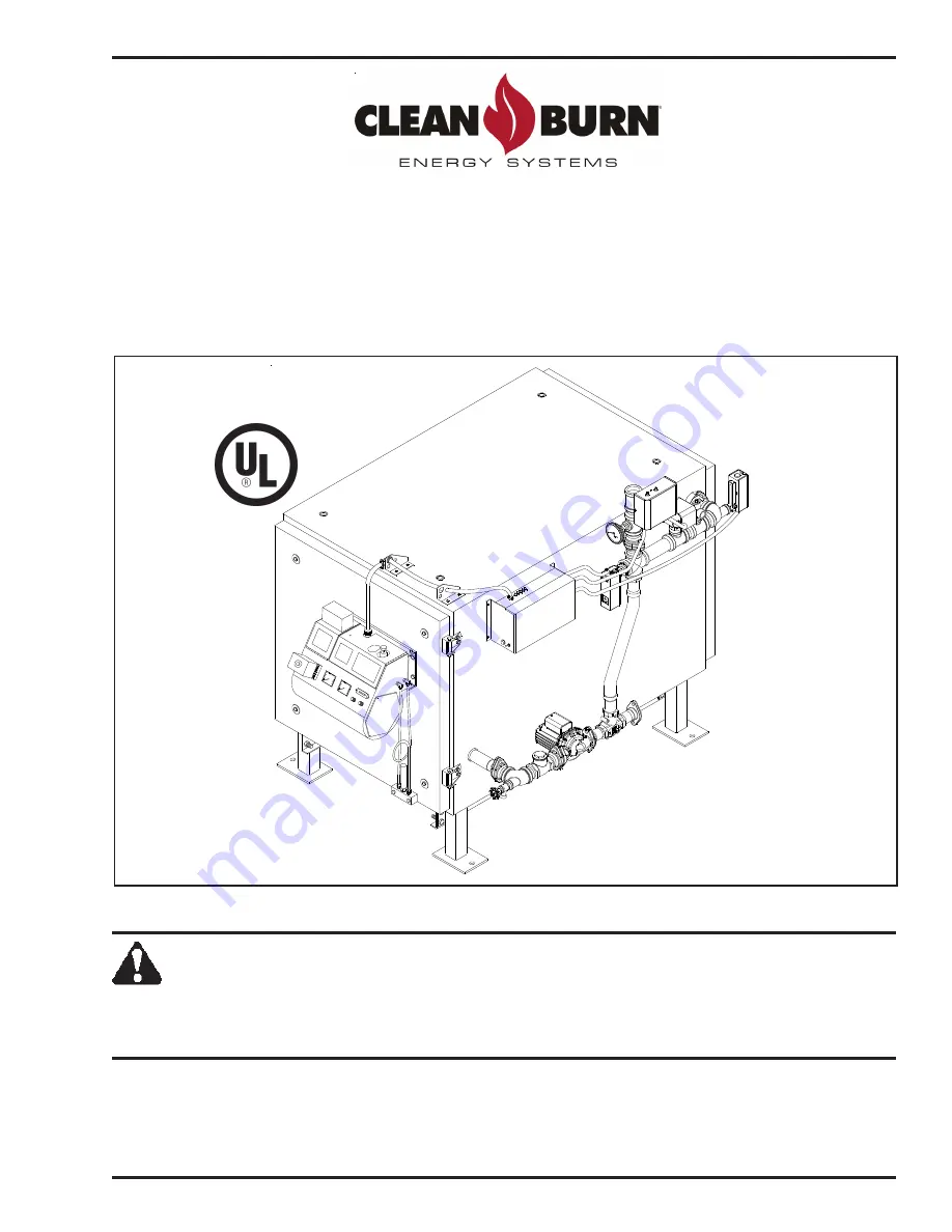
OPERATOR'S MANUAL

CLEAN BURN MODELS:

CB-200-CTB COIL TUBE BOILER 

with CB-525-S2 Burner & Metering Pump

CB-350-CTB COIL TUBE BOILER 

with CB-551-H3 Burner & Metering Pump

CB-500-CTB COIL TUBE BOILER 

with CB-551-H5 Burner & Metering Pump

IMPORTANT FOR U.S. INSTALLATIONS:  All installations must be made in accordance with state and local codes
which may differ from the information provided in this manual.  Save these instructions for reference.

IMPORTANT FOR CANADIAN INSTALLATIONS:  The installation of this equipment is to be accomplished by
qualified personnel and in accordance with the regulation of authorities having jurisdiction and CSA Standard B 139,
Installation Code for Oil Burning Equipment.

WARNING:  DO NOT assemble, install, operate, or maintain this equipment without first
reading and understanding the information provided in this manual.   Installation and

service must be accomplished by qualified personnel.  Failure to follow all safety precautions
and procedures as stated in this manual may result in property damage, serious personal injury
or death.

I88460−C

U.L. Listed Used Oil
Burning Appliance
#MH15393

Manufactured & Tested to meet
ASME Section IV

Summary of Contents for CB-200-CTB

Page 1: ...CANADIAN INSTALLATIONS The installation of this equipment is to be accomplished by qualified personnel and in accordance with the regulation of authorities having jurisdiction and CSA Standard B 139 Installation Code for Oil Burning Equipment WARNING DO NOT assemble install operate or maintain this equipment without first reading and understanding the information provided in this manual Installati...

Page 2: ......

Page 3: ...service maintenance or faulty instruction of the purchaser Other than as expressly set forth hereinabove MANUFACTURER makes no other warranty express or implied with respect to any of MANUFACTURER s products including but not limited to any warranty of merchantability or fitness for a particular purpose And in no event shall MANUFACTURER be responsible for any incidental or consequential damages o...

Page 4: ......

Page 5: ...BoilerAssembly 3 5 AssemblingtheDual StackedBoiler 3 5 AssemblyforAllBoilers 3 8 ConnectingtheCTB 3 8 InstallingtheCeramicSleeve 3 9 CheckingtheBurnerNozzleandelectrodes 3 11 MountingtheBurner 3 12 InstallingtheConnectorBlock 3 12 InstallingtheOilLineTubing 3 13 InstallingtheAirLineTubing 3 14 LockingtheBurnerintoFiringPosition 3 14 SECTION 4 COIL TUBE BOILER INSTALLATION 4 1 Understanding Install...

Page 6: ... 1 Understanding Metering Pump Priming 5 1 RequiredToolsandMaterials 5 1 PrimingtheMeteringPump 5 2 VacuumTestingtheOilPump 5 4 SECTION 6 STARTING AND ADJUSTING THE BURNER 6 1 Understanding Burner Startup and Adjustment 6 1 Preparing the Hydronics System for Burner Startup 6 1 Preparing the Burner for Startup 6 1 Starting the Burner 6 3 SECTION 7 RESETTING THE OIL PRIMARY CONTROL 7 1 Understanding...

Page 7: ...TBSetupandOperation 10 7 GuidelinesforPreventingOxygenContamination 10 8 GuidelinesforInitialCleaningandMaintainingWaterQuality 10 8 GuidelinesforCTBOperation 10 8 SECTION 11 TROUBLESHOOTING 11 1 FlowChart 11 2 TroubleshootingTables 11 3 APPENDIX A DetailedCTBSpecifications A 1 CTBTechnicalSpecifications A 1 BurnerTechnicalSpecifications A 2 CTBHydronicSpecifications A 2 CTBAccessoriesandPartsRefe...

Page 8: ...APPENDIX B WiringDiagrams B 1 CTBSequenceofOperation B 4 CTBLadderSchematic B 5 MeteringPumpWiringSchematic B 6 APPENDIX C CTBServiceRecord C 1 TABLE OF CONTENTS ...

Page 9: ...ic activities as outlined here UNPACKING PRE INSTALLATION CONSIDERATIONS Section 2 ASSEMBLY Section 3 INSTALLATION Section 4 OPERATION Oil Pump Priming Section 5 Starting and Adjusting the Burner Section 6 Resetting the Oil Primary Control Section 7 Adjusting the Draft Section 8 MAINTENANCE Section 9 THE CTB HYDRONICS SYSTEM Section 10 WARNING STOP YOUR SAFETY IS AT STAKE DO NOT INSTALL OPERATE OR...

Page 10: ...nal injury if proper precautions are not taken In addition to observing the specific precautions listed throughout the manual the following general precautions apply and must be heeded to ensure proper safe boiler operation DANGER DO NOT create a fire or explosion hazard by storing or using gasoline or other flammable or explosive liquids or vapors near your boiler DANGER DO NOT operate your CTB i...

Page 11: ...ion over environmental control building inspection and fuel fire and electrical safety and the following standards ASME Section IV Boiler Code for Pressure Vessels ASME CSD 1 Controls and Safety Devices for Automatically Fired Boilers NFPA 30 Flammable and Combustible Liquids Code NFPA 30A Automotive and Marine Service Station Code NFPA 31 Standard for the Installation of Oil Burning Equipment NFP...

Page 12: ...ns concerning the use of your boiler EPA regulations require that Your used oil is generated on site You may also accept used oil from do it yourself oil changers Hazardous wastes such as chlorinated solvents are NOT to be mixed with your used oil The flue gases are vented to the outdoors with an appropriate stack Your used oil is recycled as fuel for heat recovery DO NOT operate your boiler in wa...

Page 13: ... at right please contact your Clean Burn dealer for the label which is to be affixed directly on your used oil supply tank ONLY place these listed substances in this used oil supply tank Used crankcase oil Used automatic transmission fluid Used hydraulic oil 2 4 5 fuel oil Do NOT place flammable or corrosive substances such as gasoline chlorinated oils solvents paint thinners or any other unsafe s...

Page 14: ... safe operation of your CTB review all labels and heed all safety messages as printed on the labels If any labels on your Clean Burn CTB ever become worn lost or painted over please call your Clean Burn dealer for free replacements CTB Cabinet Labels 200 CTB 350 CTB 500 CTB Description 42288 42263 42367 AIR OIL 42457 42464 I88568 C 42496 42367 42367 42367 C B SafetyWarningLabel multiplemessages fi...

Page 15: ...B 1 7 CTB Cabinet Safety Labels 42286 42465 42216 Burn Hazard Fittings piping and boiler surface may be extremely hot Pipes contain hot water Do NOT touch without wearing protective gloves 42421 CB CTB 42286 42493 42216 42497 www cleanburn com CTB Cabinet Labels continued ...

Page 16: ...120 3 0 60 60 120 1 10 1 1 30 6 48 INPUT RATING W NO 2 FUEL OIL BTU HR 18 CB 350 CTB 2 5 16 0 350000 6 0 2 5 2 5 2 5 18 16 0 16 0 18 0 7 0 7 0 7 0 06 6 FOR COMMERCIAL OR INDUSTRIAL USE ONLY MAXIMUM FUSE SIZE WITH OPTIONS 120 120 120 POWER 1 10 1 20 400 SIDE HZ 1 4 75 3 3 60 60 60 120 1 2 20 30 5 8 17 60 42288 2 5 120 4 7 60 9 5 9 5 20 0 20 0 2 5 2 5 1 10 120 1 1 60 CERTIFIED TO ELECTRICAL AND FUEL...

Page 17: ...abels continued 30 6 48 INPUT RATING W NO 2 FUEL OIL BTU HR 18 CB 500 CTB 3 57 18 500000 18 06 6 FOR COMMERCIAL OR INDUSTRIAL USE ONLY MAXIMUM FUSE SIZE WITH OPTIONS 120 120 120 POWER 1 10 1 20 500 SIDE HZ 1 4 75 4 2 60 60 60 120 1 2 5 8 60 42496 1 2 120 5 0 60 3 57 3 57 3 57 3 57 3 57 18 3 0 24 22 18 18 3 0 3 0 2 7 2 5 2 1 1 3 120 3 9 60 30 21 0 ...

Page 18: ...HighVoltage MovingPartsHazard 42235 42235 42235 BurnerSafetyWarningLabel Fire ExplosionHazard BurnerInstallationandService 42321 42337 42494 BurnerModel Label 42229 42229 42229 C B Logo BurnerDescriptionLabel 42000 42000 42000 BurnerSafetyWarningLabel Fire ExplosionHazard ResetButton 42023 42023 42023 BurnerPowerLabel CTB BurnerSafety Labels continued I88722 B 42000 42023 42005 42235 TOPVIEW 42321...

Page 19: ...or sManual ModelsCB 200 CTB CB 350 CTB andCB 500 CTB 1 11 200 CTB 350 CTB 500 CTB Description Metering Pump Labels 42284 42284 42284 MeteringPumpWiringDiagram 42466 42420 42495 ModelNumber Warning For Your Safety continued ...

Page 20: ...CoilTubeBoilerOperator sManual ModelsCB 200 CTB CB 350 CTB andCB 500 CTB 1 12 ...

Page 21: ... valve Components packed inside boiler Ceramiccombustionchambersleeve Combustionchambersleevemountingstand Ceramic target pre mounted Canister filter Vacuum gauge Check valve with screen for tank Boiler gauge Low water cut off Tube sealant Burner hook up kit Barometricdamper Burner Oilpump CTBbasestandwithhardware DraftInducer Before assembling your coil tube boiler CTB you must accomplish the fol...

Page 22: ...equirements for your CTB installation related information in Section 4 5 The type of hydronic installation you will be using related information in Section 10 IMPORTANT NOTE If you are installing an inside oil tank in the same room as the boiler you must allow a 5 foot minimum clearance between the tank and the boiler The oil tank should be set and installed in position BEFORE the boiler is instal...

Page 23: ...iffer from these specifications RefertopagesA4throughA7forboilerdimensions Fig 2A 2B Description Clearance from Combustibles Clearance for Service A Above 18 18 B Front 24 48 C Stack 18 18 D Rear 6 40 E L H Side 6 6 F R H Side 30 30 G Bottom 6 6 G L H SIDE R H SIDE A D I88682 C DRAFT E C C F B OI L A IR D A E L H SIDE C A IR OI L F C B G A IR OI L C DRAFT I88683 C Figure 2A Single Boiler Minimum I...

Page 24: ...CoilTubeBoilerOperator sManual ModelsCB 200 CTB CB 350 CTB andCB 500 CTB 2 4 ...

Page 25: ...he assembly procedures are outlined below as they appear in this section Be sure to refer to the appropriate instructions for your CTB configuration Single Boiler Assembly Only Installing the CTB on the Support Stand Dual Stacked Boiler Assembly Only Assembling the Dual Stacked Boiler Assembly For All Boilers Connecting the CTB Installing the Ceramic Sleeve CheckingtheBurnerNozzleandElectrodes Ins...

Page 26: ...B 350 CTB andCB 500 CTB 3 2 Single Boiler Assembly Figure 3A Single Boiler Assembly Component Detail 11 SUPPLIED 13 25 DETAIL OF ITEM 24 21 1 2 3 4 5 6 7 15 16 17 18 20 19 23 22 24 26 33 27 28 29 30 31 32 I88121 F CB 350 CTB 12 34 9 14 USER SHOWN 8 10 ...

Page 27: ... 13110 LOW WATER CUT OFF 9 1 14274 LOW WATER PIPE ASSEMBLY 8 1 33330 GUAGE BOILER TEMP PRESS 7 1 35048 RELIEF VALVE 3 4 MALE 6 1 35123 FLOW SWITCH TACO 5 1 28149 HIGH TEMP CUT OFF 4 1 35079 COIL FLANGE 1 1 4 3 1 28150 AQUASTAT 2 1 31166 INSULATION PANEL 1 1 11380 PANEL 350 REAR W A NO QTY PART DESCRIPTION 34 1 90206 BASE 22 1 33546 CONNECTOR CORD 21 1 31240 INSULATION 500 DOOR 20 1 11564 DOOR W A ...

Page 28: ... insidethestandtoprovidesafetysupportforthe boiler 4 UseaforklifttocarefullylifttheCTBintopositionovertopofthesupportstand WARNING Secure the boiler to the forklift prior to lifting to prevent possible equipment damageorpersonalinjury 5 Lowertheboilerdownontothesafetyblockspositionedinsidethesupportstand 6 Insertbolts provided intothekeyholeslotsintheboiler andthenliftthestandinposition againstthe...

Page 29: ...ndintotheapproximatepositionwherethedual stackedboileristobeinstalled andplaceblocks approximately10incheshigh insidethestandto providesafetysupportfortheboiler NOTE Ifthesupportstandhasnot beenassembled refertoFigure3B NOTE Onlyuse71 2 legswhen stackingtheboilers Tallerlegsmaybe unstable 2 UseaforklifttocarefullyliftoneCTB intopositionovertopofthesupport stand WARNING Securetheboilertothe forklif...

Page 30: ... CB 350 CTB andCB 500 CTB 3 6 Dual Stacked Boiler Assembly Figure 3D Dual Stacked Boiler Assembly Detail USER SUPPLIED SUPPORT STAND REMOVE EXTRA FLANGES FROM BOILER TO INSTALL PLUMBING BOTTOM BOILER I88671 B ADAPTOR TOP BOILER BRACKET USER SUPPLIED ...

Page 31: ...lthetwounitsareassembledtogether NOTE Thenotchesontheadaptorbracketaredesignedtofitaroundstandardforkliftforks 11 Afterthebrackethasbeenattachedtotheundersideofthe top boilerunit movethe top unit intopositionoverthe bottom unit 12 Carefullylowerthe top boilerdownontothe bottom boiler watchingforalignmentofthe bracketholesandtheholesinthetopoftheboilerbelow 13 Installthehardwarethroughthelowersetof...

Page 32: ...sure gauge into the first tee the 1 2 tapping Be sure to use pipe dope on the threads of the gauge Tighten the gauge into the tee Install the probe of the low water cut off into the upper tee using pipe dope on the threads of the probe Tighten into the tee Install the low water cut off control onto the probe and secure Connect the wiring harness from the CTB control box to the low water cut off Re...

Page 33: ...F Positionthestandonthecoils approximately3 infromthedooropening 4 Aftertheceramicsleevehasbeeninstalledandpositionedproperly closetheclean outdoor 5 Tightenthefour 4 nutsandwashersinacriss crosspatternuntilallaresnug NOTE Theceramicsleeveneedstoseatfirmlyagainstthedoorinsulationforpropercombustion Carefully positiontheceramicsleeveonthestandsothatitextendsoutslightlybeyondthedooropening sothatthe...

Page 34: ...CoilTubeBoilerOperator sManual ModelsCB 200 CTB CB 350 CTB andCB 500 CTB 3 10 Figure3G CeramicStandandSleeveInstalledintheCombustionChamber Assembly for ALL Boilers I88124 B CERAMIC SLEEVE CERAMIC STAND ...

Page 35: ...le and Electrodes NOTE Theburnernozzleisfactoryinstalled ModelsCB 200 CTBandCB 350 CTBuseaDelavan9 5 nozzle ModelCB 500 CTBusesa9 28Delavannozzle Thenozzlesizeisindicatedonthenozzlesasshown inFigure3H ReferalsotoAppendixAatthebackofthemanualforadditionalspecificationsontheburner nozzle ATTENTION ChecktheelectrodesettingsasspecifiedinFigure3H Theelectrodesettingsmustbe correctforyourburnertooperate...

Page 36: ...t bolts Carefully re position the burner so it swings freely into its firing position With the burner in its firing position re tighten the hinge bracket bolts Installing the Connector Block on the CTB Door 1 RefertoFigure3Ionthenextpage 2 Use the two 2 bolts to install the aluminum connector block onto the CTB cabinet 3 Remove and discard the red caps and plugs from the fittings and ports on the ...

Page 37: ...ith the swivel assembly SlightlybendthetubingasshowninFigure 3I ifrequired to lineup theoilline 4 Make sure that the curl in the oil line is positionedasshowninFigure3Isothatthe burner can swing open correctly 5 Install the oil line tubing and tighten the nuts on the compression fittings DO NOT overtighten these fittings to avoid damaging the ferrules NOTE You may also check the positioning of the...

Page 38: ...of the burner Locking the Burner into Firing Position 1 Swing the burner into firing position 2 Install and tighten the lock nut on the mounting plate bolt to secure the burner in its firing position 3 Plug the burner electrical cable into the receptacle on the top of the burner housing 4 Tighten the locking ring to secure the electrical cable NOTE Be sure to properly align the plug when plugging ...

Page 39: ...Operator s Manual and with all national state and local codes or authorities having jurisdiction over environmental control building inspection and fuel fire and electrical safety and the following standards ASME Section IV Boiler Code for Pressure Vessels ASME CSD 1 Controls and Safety Devices for Automatically Fired Boilers NFPA 30 Flammable and Combustible Liquids Code NFPA 30A Automotive and M...

Page 40: ...E INSTALLED OIL PUMP ELECTRICAL CIRCUIT CLASS A STACK THROUGH CEILING CLASS A KIT FOR INSTALLING EQUIVALENT DEKTITE FLASHING OR WATERTIGHT ROOF FLASHING INSULATED STACK WITH A 2100 DEGREE ALL FUEL STACK CLASS A STACK CLASS A STACK CAP 1 1 2 NPT I88679 C BAROMETRIC DAMPER DRAFT INDUCER STAINLESS STEEL LINER 10 FT 3 FT FUNNEL WITH BALL VALVE OIL LINE SUCTION PUMP METERING S S E L E R O M DRAFT 5 FT ...

Page 41: ...H SINGLE CLEAN OUT TEE CLEAN OUT TEE DRAFT AT BREACH 1 4 HOLE FOR CHECKING BAROMETRIC DAMPER TO CONNECTOR BLOCKS ON BOILERS PRESSURE OIL LINES INSTALLED OIL PUMPS ELECTRICAL CIRCUIT CLASS A STACK THROUGH CEILING CLASS A KIT FOR INSTALLING EQUIVALENT DEKTITE FLASHING OR WATERTIGHT ROOF FLASHING INSULATED STACK WITH A 2100 DEGREE ALL FUEL STACK CLASS A STACK CLASS A 1 1 2 NPT 1 1 2 NPT FLANGE SET RE...

Page 42: ...ngs onenearthetopoftheenclosureandonenearthebottomoftheenclosure asfollows 1 Ifalloftheairistakendirectlyfromtheoutsideofthebuildingbyuseofverticalducts eachofthetwoopeningsmusthaveatotalfreeareaofnotlessthan1squareinchper4 000 BTU hr 35squareinchespergallonofoil ofthetotalappliance s inputrating NFPA31 Section5 4 2 2 2 Ifalloftheairistakendirectlyfromtheoutsideofthebuildingbyuseofhorizontalducts ...

Page 43: ...D SPACES ALL AIR TAKEN FROM INSIDE THE BUILDING APPLIANCES LOCATED IN CONFINED SPACES ALL AIR TAKEN FROM OUTSIDE THE BUILDING OUTLET AIR DUCT I88978 D R A FT INLET AIR DUCT APPLIANCES LOCATED IN CONFINED SPACES ALL AIR TAKEN FROM INSIDE THE BUILDING INLET AIR DUCT ENDS 1 FOOT ABOVE FLOOR OUTLET AIR D R A F T VENTILATION LOUVERS EACH END OF ATTIC AI R O I L OI L AI R OI L AI R ...

Page 44: ...be vented to theoutsideofthebuildingusingironorsteel pipeandfittingswithanapprovedventcap Carefullyreviewtheoiltankandpump installation details as shown in Figures 4A 4B and4D includingthemeteringpump installation and specifications for the oil line installation Procedures for installing these components can be found in the followingpages IMPORTANTNOTE Ifyouareinstallinganinsideoiltankinthesameroo...

Page 45: ...llationguidelines Install a length of minimum 2 steel pipe user supplied terminating outside with a proper ventcapasshowninFigure4D Consultlocalcodesforinformationandrequirements concerning the proper venting of oil storage tanks InstallanemergencyventasshowninFigure4D Contactyourtankmanufacturerfor information concerning the proper emergency vent for your tank SCREEN FILTER PUMP SUCTION LINE ASSE...

Page 46: ...thispumpinstallationisrecommended Alternate mounting is horizontal mounting on a bracket Be sure to carefully follow the appropriateprocedures diagramsforpumpmounting Foroptimalmeteringpumpfunctioning mountthepumpatadistancefromtheoiltankthatwill complywiththefollowingrequirements The suction oil line may NOT exceed6 feet TOTAL vertical lift AND 4 feet TOTAL horizontallift Figure4E Standard Recomm...

Page 47: ... CB 350 CTB 33291 SATURN 140 CB 500 CTB 33558 21 22 24 26 25 24 CB 3250 33572 2 10 PART DESCRIPTION 1 33363 CAPACITOR GEARMOTOR 9 32526 MINI BALL VALVE 1 8 MNPT X 1 8 FNPT 3 11322 MOUNT METER PUMP 10 32475 METER PUMP 8 N A 1 8 M NPT X 3 8 OR 1 2 FLARE 7 N A 3 8 OR 1 2 COPPER OR ALUM TUBING 6 N A 3 8 OR 1 2 TUBE FLARE NUT 5 N A 1 4 COPPER OR ALUM TUBING 13 32336 1 4 X 3 4 BRASS BUSHING 15 32127 CAN...

Page 48: ...inFigure4G 4 Re install and tighten the two pump mounting bolts 5 Use the appropriate type of bolts and washers user supplied to securely mount the metering pumptothemountingbracket whichistobeinstalledontheappropriatewallinyourbuildingata distancefromthetankthatcomplieswiththesuctionoillinerequirements GAUGE INLET RECOMMENDED SETUP PUMP IS MOUNTED LEFT ON WALL ALTERNATE MOUNTING TO THE WALL MAKIN...

Page 49: ...vicing Filling the Coil Tube Boiler with Water ATTENTION It is necessary to fill the CTB with water prior to wiring and turning the CTB ON The boiler circulator bearings are water lubricated and should not be allowed to operate dry Filling the CTB with water provides immediate lubrication of the bearings Purging air from the water is also critical doing so enables proper startup of the burner 1 Fi...

Page 50: ...passembly Samplecalculation 6 verticalfeetx0 75 4 50 hgAND 4 horizontalfeet 0 75 hg 4 50 hg 0 75 hg 0 75 hg 6 00 hgvacuum Themeteringpumpmustbeinstalledwitha3 4 checkvalveandscreenattheendofthe suctionoilline orthepumpwillnotmaintainitsprime Use Permatex 2 non hardening gasket sealer on every threaded fitting DO NOT use teflontapeorteflonpipedopecompounds thetefloncanflakeoffandcausedamagetothe pu...

Page 51: ...rtubing h Removethelockingnutandferrelsleeveconnectorfromthe1 2 slipfitting andslidethem overthecoppertubing i Slidethe1 2 O D coppertubingthroughthe1 2 slipfitting whichisinstalledinthe S sideofthe2 hexbushing j Installthescreenintoonesideofthe3 4 checkvalve makingsurethearrowispointing awayfromthescreenassembly k Installthe3 4 x1 2 brassbushingintothe3 4 checkvalve l Installthe1 2 MPTx1 2 flarea...

Page 52: ...youseethemarkthatyouput onthetubingearlier Holdingthetubingwithonehand pushtheferrelsleeveconnectorand lockingnutdownthetubing thentightenontothe1 2 slipfitting Theoillineisnow installedinthecorrectpositionoffofthebottomofthetank r Carefullybendtheoillineuptothecanisterfilter useaspringbenderovertheoillinewhile bendingthetubingtopreventkinksintheoilline Allowingfortheflarenut cutoffthe excesstubin...

Page 53: ...rythreadedfitting DONOTuseteflon tapeorteflonpipedopecompounds 1 RefertoFigure4H 2 Removetheplugfromthereliefportontopofthemeteringpumphead 3 Installthe1 8NPTx1 4tubecompressionfittinginthereliefportontopofthemeteringpumphead 4 Install1 4 O D coppertubing user supplied fromthepressurereliefportbacktotheoiltank RefertoFigure4Dasneeded Figure 4H Pressure Relief Oil Line Back to the Tank PART DESCRIP...

Page 54: ...xtinguished and the burner will shut down Be sure to drain water from your compressor tank on a regular basis to keep water out of the air line ATTENTION It is critical that you adhere to the following specifications for pressure oil line installation oil line from the pump to the boiler if these specifications are not met the metering pump will not function correctly and the burner will shut down...

Page 55: ... Install a dedicated electrical circuit to the electrical junction box on the CTB Note that a dual stacked boiler will require two circuits each with a single pole single throw breaker CAUTION DO NOT tie into an existing circuit or electrical overload may occur 2 Wire the CTB according to the Wiring Schematic in Appendix B Use 12 gauge copper wire for a 15 or 20 amp breaker A 30 amp breaker requir...

Page 56: ...of cold water returned to the boiler and to protect the boiler from thermal shock an optional circulator aquastat can be supplied by your Clean Burn Dealer 1 Refer to the related information and illustrations in Section 10 and the CTB Wiring Diagram in Appendix B to locate and understand the wiring for the load loop circulator 2 ThecoldwaterreturninyourCTBsysteminstallationshouldnotbebelow140o F N...

Page 57: ...ack run as short as possible slant it upward at a minimum of 1 4 per footofrun Keep the stack design simple Complicated stacks with long runs and many turns reduce draft and result in poor burner performance Your stack may include only one 90 degree turn All other stack turns must be at 45 degrees or less to ensure optimal draft and burner performance NOTE If you plan to use an existing masonry ch...

Page 58: ...kehoodbreach 8 INCH MINIMUM EQUIVALENT DEKTITE OR 3 FEET A STAINLESS STEEL LINER 10 FT MINIMUM VERTICAL STACK HEIGHT OR EQUIVALENT DRAFT SYSTEM TO MAINTAIN 02 W C DRAFT OVER FIRE 10 FEET GALVANIZED STRUCTURE WITHIN 10 FEET OF IT AND AT LEAST 3 FEET HIGHER THAN ANY RIDGE PARAPET WALL OR ROOF THE LAST STACK SECTION SHALL EXTEND AT LEAST 3 FEET ABOVE THE HIGHEST POINT AT WHICH IT COMES IN CONTACT WIT...

Page 59: ...essaryservicecalls Allotherturnsinthestackshouldbeata45 degree orsmaller angle Installing the Barometric Damper s 1 RefertoFigure4K Installasinglewalltee min 24gauge onthefirststraightverticalor horizontalstacksectionwithinthreefeetoftheCTBbreach NOTE This tee is required to support the barometric damper You must purchase this tee when youpurchaseyourstackmaterials 8 singlewalltee CB 70174 10 sing...

Page 60: ...etric damper ortheflapperofthedamperwillnotoperatecorrectly NOTE Specificationsforadjustingthebarometricdamperforproperdraftoverfireareprovidedin Section8ofthismanual I88539 8 CLEAN BURN BAROMETRIC DAMPER INSTALLED IN SINGLE WALL TEE ADJUST THIS WEIGHT TO OBTAIN PROPER DRAFT 1 No QTY PART DESCRIPTION 8 BAROMETRIC DAMPER 31170 1 1 Figure4K InstallationofBarometricDamper DAMPER WITH ADAPTOR IN 9 CLE...

Page 61: ... NOTE Thebarometricdampermustbeinstalledsothatitislevelandtheflappermovesfreely 2 EnsurethatmainpowertotheheatingequipmentisturnedOFF 3 PositionthestacksafetyswitchoverthelipofthebarometricdamperasshowninFigure4L 4 Drilla1 8 pilotholeforthemountingscrew andmountthestacksafetyswitchusingthemounting screwsuppliedwiththeswitch NOTE Themountingscrewmustnotinterferewiththefreemovementoftheflapperontheb...

Page 62: ...ttingthestacksafetyswitch checkthestacktomakesureitisclearofanyobstructions 2 Removethecoverfromthestacksafetyswitch andpushthesmallbuttoninthemiddleoftheswitch 3 Pushingthestacksafetyswitchresetbuttonwillre establishthethermostatcircuit andtheburnerwill start assumingthewallthermostatiscallingforheat Figure 4M Stack Safety Switch Wiring Diagram Understanding the Function of the Stack Safety Switc...

Page 63: ...stack manufacturer 3 Install water tight roof flashing around the penetration of the exterior stack NOTE Clean Burn recommends the use of Dektite roof flashing or equivalent which ensures a water tight seal when installed properly Contact your local Clean Burn dealer for details Installing the Stack Cap NOTE Proper installation of a Class A UL103 HT stack cap ensures the free flow of stack gases w...

Page 64: ...of the Draft Inducer 3 FEET 10 FEET DRAFT S S E L E R O M I88968 B SERVICEMAN ADJUSTS BAROMETRIC DAMPER TO OBTAIN 02 W C DRAFT OVERFIRE DRAFT ADJUSTMENT PLATE DRAFT INDUCER NOTE INSTALL DRAFT INDUCER IN LAST SECTION OF VERTICAL STACK TO POSITION DRAFT INDUCER AWAY FROM BOILER BREACH SO THAT THE MOTOR DOES NOT OVERHEAT THIS ALSO REDUCES ASH ACCUMULATION IN THE DRAFT INDUCER DO NOT MOUNT THE DRAFT I...

Page 65: ...control withoutremovingoneofthewires Failuretoremoveoneofthewireswillburnouttheheatanticipator onthethermostatandwillcausethethermostattofail 6 Mountthethermostatbase60 to66 fromthefloorusingthehardwareprovided 7 Reassemble the thermostat body onto the base Align the hinges at the bottom of the cover with the slots at the bottom of the base and swing the cover up into place Installing the Wall The...

Page 66: ...d local codes and allows for any deficiencies in the installation to be corrected before CTB startup Improper installation will void your warranty NOTE Important During the inspection be sure to check the aquastat settings Initial settings are listed here OperatingAquastat 180o F minimum Hi limitAquastat withmanualreset 240 o F RefertoSection6forburnerstartupandfinaladjustmentsoftheaquastat Any ch...

Page 67: ...erlyprimethepump IMPORTANTNOTEFORDUAL STACKEDUNITS Theprimingprocedureswillhavetobeper formedforoneburner andthenrepeatedfortheotherburner i e getoneburnerrunningfirstbeforeattempting primingoftheotherburner Required Tools and Materials The following tools and materials are required for oil pump priming and should be gathered before starting any procedures 3 8 open endwrench 5 8 open endwrench Rag...

Page 68: ... out of the side of the pump head this will fill the oilline canisterfilter andpumpheadwithoil ATTENTION NEVERrunthepumpheaddry i e withoutoilinthepumphead Doingsowill severelydamagethepump 4 ApplyPermatex 2non hardeninggasketsealertothethreadsoftheplug removedfromthe pumphead Re installtheplugandtighten 5 ApplyPermatex 2non hardeninggasketsealertothethreadsofthe1 2 brassnipple Re install the1 2 b...

Page 69: ...itch is in this position The oil primary control circuit is de activated so the burner cannot run while the switch is in the UP position BURNER switch is in the DOWN position this is used for normal burner operation When the switch is in the DOWN position the burner controls the operation of the pump The pump will only run while the burner is running a RefertoFigure5Btolocatetheprimingswitch b Tur...

Page 70: ...setheballvalveattheinlettothecanisterfilter Observethevacuumgauge NOTE Theballvalvemusthaveastainlesssteelballandshouldbepressuretestedbythe manufacturertoensurethatitdoesnotleak Iftheballvalveleaks thevacuumtestwillnotbe accurate 4 Thevacuumshouldincreasewithin30secondsto15inchesofvacuum Whenthevacuum gaugereads15inchesofvacuum firstcloseandtightenthebleeder thenturnthepumpoffandclose theminiball...

Page 71: ... more leaks somewhere between the pump and the ball valve Do the following Wipe your finger along the cylinder at the shaft of the pump If there is oil here the pump seal is damaged Replace the pump Disassemble and clean all the fittings from the pump to the ball valve Properly seal all fittings with Permatex 2 non hardening gasket sealer or equivalent Check the condition of the o ring on the cani...

Page 72: ...CoilTubeBoilerOperator sManual ModelsCB 200 CTB CB 350 CTB andCB 500 CTB 5 6 ...

Page 73: ...ged from the system If the CTB circulator becomes air bound it will not produce sufficient flow to activate the flow switch and the burner will not start properly 1 Turn the load temperature controller i e thermostat or aquastat OFF 2 Set the operating aquastat on the CTB at 180 to 200 o F Preparing the Hydronics System for Burner Startup Preparing the Burner for Startup 1 If you have not already ...

Page 74: ...ustbeproperlyadjustedtoensurethattheburner ignites and burns correctly DO NOT attempt to start the burner with the combustion air band wide open or completely closed The burner may not ignite correctly Failure to heed this warning may result in a fire or explosion hazard IMPORTANT NOTE This initial setting of the combustion air band will allow you to start the burner You will fine tune the combust...

Page 75: ...thanone halfofthewaydownthechamber WARNING Theobservationportgetshotasthe burner fires To avoid personal injury always wear heavy work gloves and safety glasses when opening the port andviewingtheflame CAUTION WHENOPENINGINSPECTIONPORT PORT MAY BE HOT PROTECT HANDS WEAR SAFETY GOGGLES KEEP FACE AWAY OPEN PORT SLOWLY Maximum Input 350 000 BTUH 2 5 GPH per CB 551 H3 Burner OilType Oil PSI Flame Leng...

Page 76: ...372 Starting the Burner continued CorrectMaximumFlameAdjustment ProperOilandAirPressure Flamegoeshalfofthewaydownthe combustionchamber Flamedoesnottouchbackofwallsof combustionchamber IncorrectFlameAdjustment NotEnoughCombustionAir Flamemustnottouchbackorwallsof combustionchamber Increasecombustionairbyopeningthe airbandonthesideoftheburner IncorrectFlameAdjustment AirPressuretoohigh Ensurepropera...

Page 77: ... band 1 8 to 1 4 and re check the flame for the proper characteristics Re check the flame after five minutes You should see a yellow white flame with sharp tips and no sparkles and the flame should extend half of the way down the combustion chamber 12 Checking for a Smokeless Burn Check for a smokeless burn by observing the stack while the burner is running If you see any smoke repeat the previous...

Page 78: ...CoilTubeBoilerOperator sManual ModelsCB 200 CTB CB 350 CTB andCB 500 CTB 6 6 ...

Page 79: ... CB 525 S2 Burner DANGER DO NOT push the reset button more than once DO NOT push the reset button if oil mist is present in the combustion chamber or when the combustion chamberishot DONOToperateyourboilerif excessoil oilvapororfumeshaveaccumulatedinor nearyourboiler Aswithanyoilburning appliance improperoperationmayresultina fireorexplosionhazard 1 RefertoFigure7A 2 Checkthecombustionchamberforfu...

Page 80: ...resent in the combustion chamber or when the combustion chamber is hot DO NOT operate your CTB if excess oil oil vapor or fumes have accumulated in or near your boiler As with any oil burning unit improper operation may result in a fire or explosion hazard 1 RefertoFigure7B 2 Check the combustion chamber for fuel mist by shining a flashlight through the observation port If you see fog fuel mist in...

Page 81: ...r blinking ON OFF for approximately 10 seconds the red and amber LED s will go out Continue to hold the reset button for an additional 15 seconds and then release the button d The burner will now start NOTE Releasing the reset button at any time during this procedure step 8 will cause the unit to remain in latch up and you will have to start the procedure again 9 When the load temperature controll...

Page 82: ...CoilTubeBoilerOperator sManual ModelsCB 200 CTB CB 350 CTB andCB 500 CTB 7 4 ...

Page 83: ... port in the observation port as shown in Figure 8A 2 Adjust the barometric damper to achieve the required draft over fire of 0 02 w c water column 3 Record the reading in the Maintenance Record located in the Appendixes 4 If correct draft over fire cannot be achieved contact your Clean Burn dealer immediately ATTENTION Only operate your CTB with a draft over fire of 0 02 w c Poor draft results in...

Page 84: ...the building or in another room away from the boiler the exhaust fan will still create backdraft at the boiler Checking Draft Overfire to Determine Severity of Backdraft The following procedure is an accurate method of determining how much backdraft is created by the exhaust fans Once this is determined you can select the correct method for resolving the backdraft 1 Turn off ALL exhaust fans and c...

Page 85: ...t Whenadjustingthebarometric damper youwillfindthattheflapperisopenmostofthetime Thisallowsthedraftinducertosuckcoolair throughthedampertoprotecttheinducermotorfromheatdamage 1 Useadraftgaugetocheckdraftoverfire 2 Adjustthebarometricdampertoobtain 0 02w c draftoverfire Ifyoustillhavetoomuchdraft adjustthedraftplateonthedraftinducer Movetheplatein1 4 toreducethedraft Recheck thedraftreading ...

Page 86: ...CoilTubeBoilerOperator sManual ModelsCB 200 CTB CB 350 CTB andCB 500 CTB 8 4 ...

Page 87: ...x every750hrs perburnerhourmeter Cleaningoutash CB 350 CTB Approx every1000hrs perburnerhourmeter Cleaningoutash CB 500 CTB Approx every1000hrs perburnerhourmeter Cleaning MaintainingtheDraftInducer At least once a year Checkingboilerwatercondition Periodicallybyqualifiedwatertreatmentcompany Annual burner tune up At least once a year ItisveryimportanttocleantheashfromtheCTBonschedule Normaluseoft...

Page 88: ...owl and filter element Now pour the oil into the container 4 Clean the filter element and the bowl in a parts washer 5 Referring to Figure 9A check the condition of the O rings Replace any that are cracked or worn 6 Ensure that the canister filter is 100 airtight by firmly tightening the four bolts 7 Open the ball valve Refer to Sections 5 and 6 for instructions on priming the pump and starting th...

Page 89: ...h inside and outside tanks The following protective gear should be worn when cleaning the check valve screen Rubber gloves Safety goggles 1 RefertoFigure9C Removetheone piecesuctionoillinefromthetank 2 Removethecheckvalveandscreen Cleanthesecomponentsinapartswasher 3 Check the operation of the check valve The valve must seat so it is airtight to hold pump prime 4 Re assemble and re install the com...

Page 90: ...ucesheattransfersignificantly Neverallowmore than1 4 ofashtoaccumulateinthecombustionchamber heatexchangerfluesorstack Thefollowingprotectivegearshouldbewornwhencleaningtheash Respiratorforfineparticles Rubbergloves Safetygoggles Protectiveclothing 1 EnsurethatpowerhasbeenturnedOFF andall hot componentshavebeenallowedtocool sufficiently ShopairshouldbeturnedOFFanddisconnected Allowatleastonehourfo...

Page 91: ...iningashresiduefromthefluepassages Alongwandonthe hoseofyourshopvacishelpfulinreachingallthewayback h Inspectthecombustionchamberanditscomponentstoensurethatitisingoodcondition Inspect the inside of the clean out door and target wall Make sure the refractory material on the inside of the door is in good condition and the door seals tightly when closed If the door does not seal tightly replace any ...

Page 92: ...lercomponents ceramicstand ceramicsleeve backpanel etc Ifnecessary refer toSection3foradditionalAssemblyinformation 5 Closetheclean outdoor installandtightenthewasherandnuts Makesurethattheclean out door and rear panel close and seal properly Reconnect all disconnected lines oil and air on the bottom of the connector block NOTE You may need to bleed air from the oil line before starting the burner...

Page 93: ... should be made to the following standards 1 Current Edition of American National Standard ANSI NFPA 31 Installation of Oil Burning Equipment for clearances between boiler vent connector and combustible material 2 Current Edition of American National Standard ANSI NFPA 211 Chimneys Fireplaces Vents and Solid Fuel Burning Appliances for chimney requirements type of venting material and clearances b...

Page 94: ... operating aquastat setting should be no less than 180 o F The high limit aquastat factory recommended setting is 220 240 o F The 140 o F Mixing Valve must be installed according to Figure 10B or 10C and must be as close as possible tothesuctionsideoftheboilercirculator Thisallowstheby passlooptofunctionproperly Whenstarting theboilerfromcold roomtemperature theboilerwatertemperaturewillbeabletoco...

Page 95: ... 12 APART CONCEPTUAL SCHEMATIC THE DESIGNER MUST DETERMINE IF IT WILL WORK WITHIN THE SYSTEM AND ENSURE COMPLIANCE WITH EXISTING CODES I88673 COLD SUPPLY WATER DOMESTIC HOT WATER INDIRECT WATER HEATER UNIT HEATER HYDRONIC CTB PRIMARY LOOP CIRCULATOR PRIMARY SECONDARY SYSTEM WITH MULTIPLE OR SINGLE BOILERS ENHANCED TYPE OPTIONAL HEAT EXCHANGER AND CIRCULATOR MAY BE REQUIRED IF ANTIFREEZE IS USED IN...

Page 96: ... may have ordered from Clean Burn for your CTB system is sized to ensure a flow of water through the coil tube ONLY it is NOT sized to be used as a system circulator TheboilercirculatormustbeinstalledaccordingtoFigures10Band10C afterthemixingvalve An additionalcirculatormustbeinstalledtoflowwaterthroughthesystemandtotheboiler 2 In low load conditions Clean Burn recommends the installation of a lar...

Page 97: ...PLIED BOILER CIRCULATOR SYSTEM RETURN SYSTEM SUPPLY CIRCULATOR WATER COLD ISOLATION VALVE THE DESIGNER MUST DETERMINE IF THIS SYSTEM CONCEPTUAL SCHEMATIC WILL WORK WITHIN THE SYSTEM AND ENSURE COMPLIANCE WITH EXISTING CODES AIR SEPARATOR ENHANCED TYPE BOILER WATER STORAGE TANK AIR ELIMINATOR FILL VALVE SYSTEM SUPPLY PURGE VALVE I88676 B ...

Page 98: ...IR SEPARATOR ENHANCED TYPE AIR ELIMINATOR THE DESIGNER MUST DETERMINE IF THIS SYSTEM CONCEPTUAL SCHEMATIC WILL WORK WITHIN THE SYSTEM AND ENSURE COMPLIANCE WITH EXISTING CODES PURGE VALVE ISOLATION VALVE WATER HEATER FILL VALVE WATER COLD I88674 B WATER INLET HEAT EXCHANGER HOT WATER ERGOMAX OUTLET USER SUPPLIED BOILER CIRCULATOR ...

Page 99: ...lves or balancing valves c Attach a hose to the purge valve located just below the isolation valve in the boiler supply piping NOTE Ensure that the end of the hose drains into a bucket located in a drain area or outside d Starting with one circuit open the first zone valve ONLY e Open the purge valve f Open the fill valve the make up water line should be located on the system side of the isolation...

Page 100: ...rfaces These protective coatings are commonly applied to new tubes to prevent rusting during storage transit and will cause corrosion if left on the tubes during operation of the boiler After cleaning the boiler drain the system in a manner and to a location that hot water can be discharged safely Remove plugs from all available locations and wash the water side of the boiler as thoroughly as poss...

Page 101: ...ng any difficulties encounteredinboileroperationandadjustment TheFlowChartoutlinesthepropersequenceofeventsinboileroperation usethis chart to help diagnose where a problem may be occurring More specific troubleshooting information is provided in the Troubleshooting Tables following the flow charts Each table lists a Problem Possible Cause and Possible Action s to fix the problem ...

Page 102: ... 10 psi of air pressure Pump circuit starts oil pump Yellow indicator light ON Pump circuit opens oil solenoid Air sensing switch receives power from centrifugal switch INITIAL START UP Combustion air band adjusted for proper combustion air Centrifugal switch closes and sends power to air sensing switch Burner motor starts and reaches full rpm Burner ignites Oil primary control receives 500 ohm si...

Page 103: ...ck of the burner it should be 140 degrees F If the heater block is NOT HOT a Wait 15 minutes for the heater block to heat up and re check the back of the burner and b Check the block heater thermostat and block heater element Refer to the wiring diagram and ladder schematic in Appendix B 4 If the block is HOT a Check the red wire at the F 120 proving switch for power If there is NO power at the re...

Page 104: ...haust fans in your building Follow instructions in Section 8 5 Disconnect the yellow wires from the F terminals Start the burner and check the ohm reading from the cad cell You have 10 seconds to perform this test before the burner shuts off on reset Refer to Section 7 to reset the oil primary control If the ohm reading is above 500 ohms a Check the position of the cad cell the cad cell must look ...

Page 105: ...ck for proper ohm signal Follow the procedures in the previous problem top page 11 4 3 Follow the instructions in Section 5 to adjust the air regulator for proper air pressure DO NOT turn the air compressor off while the boiler is operating If you turn the air compressor off at night turn the wall thermostat or aquastat OFF so the burner will not run 4 DO NOT shut off power to the boiler overnight...

Page 106: ... 100 airtight 2 Make sure the pump head is filled with oil prior to starting the pump See Section 5 3 Follow the procedure in Section 5 to fill the oil line and prime the pump 4 With the pump not running wipe your finger along the bottom of the cylinder at the pump shaft If there is oil at the pump shaft the seal is damaged Replace the pump or replace the seal NOTE Some oils will expand as they wa...

Page 107: ... does NOT come ON there is a problem with pump circuit in the burner With the burner running check for power at the brown wire on the air pressure switch If there is NO power at the brown wire replace the burner motor If there is power at the brown wire replace the air sensing switch 2 a The pump motor is too hot the internal thermal protection switch shut the motor off Wait for the motor to cool ...

Page 108: ...CoilTubeBoilerOperator sManual ModelsCB 200 CTB CB 350 CTB andCB 500 CTB 11 8 ...

Page 109: ...4 x 34 5 66 38 x 40 x 42 Overall Length with burner breach 59 74 86 13 Approximate Weight 677 lbs dry 1240 lbs dry 1600 lbs dry Mounting Non Combustible Floor Non Combustible Floor Non Combustible Floor Electrical Requirements VAC 60 Hz 115 115 115 Circuit Breaker 15 amps 20 amps 20 amps Approximate Amp Draw 9 10 12 Max Oil Consumption 1 4 GPH 2 5 GPH 3 57 GPH Oil Pump Suntec A2RA 7720 Suntec A2RA...

Page 110: ... of head CB 500 CTB Hydronic Specifications NOTE ThesespecificationsapplyforeachCTBunitorcoil Waterflowthroughtheboiler Coil Dry Weight 530 lbs 37 GPM at 22 ft of head pressure System operating pressure 12 to 22 psi 20 o Ftemperature rise ΔΤ Standardreliefvalvesetting 30psi ASMEcoillength 195ft long 1 1 2 diameter Reliefvalvecapacity 970MBH steeltubingmadetoSch 40pipesize Heating surface 97 sq ft ...

Page 111: ...geGasket 3 hole 28150 28150 28150 OperatingAquastat L4006A 35110 35110 35110 ElectronicLowWaterCut OffwithProbe 750P MT 120 35111 35111 35111 Probe only forLowWaterCut Off 28149 28149 28149 HighTemperatureCut off L4006H 35123 35123 35123 TacoFlowSwitch withoutpaddle 35124 35124 35124 StainlessSteelPaddleforTacoFlowSwitch sizedtofit 35117 StainlessSteelPaddleforM MFlowSwitch sizedtofit 33330 33330 ...

Page 112: ...ROL BOX BLOCK AIR OIL CONNECTOR VALVE RELIEF CONNECTION ELECTRICAL TEMP PRESSURE FLOW SWITCH GAUGE 8 DIA FLUE COLLAR I88846 D HIGH LIMIT W RESET FRONT SERVICE CLEARANCE REAR SERVICE CLEARANCE CUT OFF LOW WATER 40 48 20 39 5 4 0 36 RETURN 1 1 4 NPT 1 1 4 NPT SUPPLY 5 75 29 2 75 5 12 29 25 8 0 4 8 19 25 12 5 7 5 OR 11 75 LEG LENGTH CTB Dimensions ...

Page 113: ...LOCK AIR OIL CONNECTOR VALVE RELIEF CONNECTION ELECTRICAL TEMP PRESSURE FLOW SWITCH GAUGE 8 DIA FLUE COLLAR I88677 C HIGH LIMIT W RESET FRONT SERVICE CLEARANCE REAR SERVICE CLEARANCE CUT OFF LOW WATER 5 0 40 12 5 48 34 75 56 5 36 RETURN FLANGE SET 1 1 2 NPT SUPPLY 21 50 34 5 5 34 25 1 1 2 NPT 6 5 6 0 7 5 OR 11 75 LEG LENGTH AIR OIL CTB Dimensions ...

Page 114: ...X CONNECTION CONNECTOR ELECTRICAL 48 5 86 0 79 50 BLOCK 34 25 7 5 13 5 5 36 5 1 1 2 NPT SUPPLY AIR OIL SUPPLY 1 1 2 NPT 48 56 34 75 40 12 5 5 I88678 C CLEARANCE SERVICE REAR FLOW SWITCH TEMP PRESSURE GAUGE CUT OFF LOW WATER COLLAR FLUE 8 DIA HIGH LIMIT VALVE RELIEF W RESET 1 1 2 NPT FLANGE SET RETURN RETURN FLANGE SET 1 1 2 NPT 21 50 USE ONLY 7 5 LEG LENGTH WHEN STACKING BOILERS AIR O IL AIR O IL ...

Page 115: ...E RELIEF CONNECTION ELECTRICAL TEMP PRESSURE FLOW SWITCH GAUGE 10 DIA FLUE COLLAR I88967 C HIGH LIMIT W RESET FRONT SERVICE CLEARANCE REAR SERVICE CLEARANCE CUT OFF LOW WATER 40 12 5 48 44 5 66 5 3 75 36 RETURN FLANGE SET 2 NPT SUPPLY 23 41 75 39 75 2 NPT 16 1 6 44 3 6 1 7 5 OR 11 75 LEG LENGTH 7 75 10 25 6 FOR A 7 8 OR 12 1 STAND HEIGHT AIR OIL CTB Dimensions ...

Page 116: ... CONTROL BOX CONNECTION CONNECTOR ELECTRICAL 60 75 101 94 75 BLOCK 39 75 7 8 15 5 3 75 36 2 NPT SUPPLY AIR OIL SUPPLY 2 NPT 59 75 66 5 44 5 40 12 6 75 I88979 B CLEARANCE SERVICE REAR FLOW SWITCH TEMP PRESSURE GAUGE CUT OFF LOW WATER COLLAR FLUE 10 DIA HIGH LIMIT VALVE RELIEF W RESET 2 NPT FLANGE SET RETURN RETURN FLANGE SET 2 NPT 23 3 USE ONLY 7 5 LEG LENGTH WHEN STACKING BOILERS 10 25 AIR OIL ...

Page 117: ...CoilTubeBoilerOperator sManual ModelsCB 200 CTB CB 350 CTB andCB 500 CTB A 9 ...

Page 118: ... 350 CTB andCB 500 CTB A 10 Single Boiler Assembly Figure A5 Single Boiler Assembly Component Detail DETAIL OF ITEM 24 21 1 2 3 4 5 6 7 15 16 17 18 20 19 23 22 24 26 33 27 28 29 30 31 32 I88121 F CB 350 CTB 12 34 9 14 USER SHOWN 8 10 11 SUPPLIED 13 25 ...

Page 119: ...1 13110 LOW WATER CUT OFF 9 1 14274 LOW WATER PIPE ASSEMBLY 8 1 33330 GUAGE BOILER TEMP PRESS 7 1 35048 RELIEF VALVE 3 4 MALE 6 1 35123 FLOW SWITCH TACO 5 1 28149 HIGH TEMP CUT OFF 4 1 35079 COIL FLANGE 1 1 4 3 1 28150 AQUASTAT 2 1 31166 INSULATION PANEL 1 1 11380 PANEL 350 REAR W A NO QTY PART DESCRIPTION 34 1 90206 BASE 22 1 33546 CONNECTOR CORD 21 1 31240 INSULATION 500 DOOR 20 1 11564 DOOR W A...

Page 120: ...CB 200 CTB FigureA6 CB 525 S2BurnerComponentDetail CB 200 CTB 3 5 6 18 21 23 15 10 13 11 12 16 5 4 14 4 19 20 22 SEE ILLUSTRATION I88543 FOR PART NUMBERS 25 1 3 2 1 1 1 2 1 7 6 8 1 9 0 1 2 3 4 5 6 7 8 9 10 11 0 12 13 14 15 psi 60 30 20 50 psi 40 0 10 24 27 I88234 C CB 525 S2 BURNER 9 1 2 7 8 17 26 ...

Page 121: ... 8 32178 OIL GAUGE 0 15 PSI 9 32235 FEMALE ELBOW 3 16 T x 1 8 NPT 10 32179 AIR GAUGE 0 60 PSI 11 32253 FEMALE ELBOW 1 8 TP x 1 8 NPT 12 33297 HOUR METER 60 Hz 13 33169 GREEN LIGHT POWER 14 33168 AMBER LIGHT PUMP 15 31113 FAN SQUIRREL CAGE 16 26044 MOTOR MOUNT PLATE 17 33175 BLOWER MOTOR 18 26053 RIGHT SIDE COVER 19 11335 HOUSING INCLUDES ITEM 23 20 13148 HEATER BLOCK ASSEMBLY 21 11265 COVER HINGED...

Page 122: ... CB 350 CTB FigureA7 CB 551 H3BurnerComponentDetail CB 350 CTB 0 9 1 8 6 7 1 2 1 1 1 2 3 1 25 16 7 6 2 1 8 BURNER CB 551 H3 I88239 B 26 23 15 11 10 12 9 14 24 22 20 21 17 5 4 3 19 18 NUMBER I88543 FOR PARTS SEE ILLUSTRATION 13 4 5 10 0 40 psi 50 20 30 60 psi 15 14 13 12 0 11 10 9 8 7 6 5 4 3 2 1 ...

Page 123: ...78 OilGauge 0 15psi 8 32235 FemaleElbow 3 16Tx1 8NPT 9 32179 AirGauge 0 60psi 10 32253 FemaleElbow 1 8TPx1 8NPT 11 33297 Hour Meter 60 Hz 12 33169 GreenLight Power 13 33168 AmberLight Pump 14 31113 FanSquirrelCage 15 26044 MotorMountingPlate 16 33175 BlowerMotor 17 14085 RightSideCover 18 11335 Housing includesitem23 19 13148 HeaterBlockAssembly 20 11265 Cover Hinged 21 SEENOTE NozzleAdapterAssemb...

Page 124: ...lock and Electrode Assembly Component Detail CB 525 S2andCB 551 H3Burners CB 200 CTBandCB 350 CTB 14 26 24 30 29 59 32 31 8 8 11 12 2 1 5 4 22 23 21 2 2 16 18 19 34 41 42 43 39 40 36 38 45 35 33 44 17 20 37 3 48 49 50 51 52 53 54 55 56 57 58 9 8 7 10 6 I88543 A 4 2 27 13 28 0 9 1 8 4 5 6 7 1 2 3 1 1 12 3 1 15 17 60 25 47 46 46 ...

Page 125: ...ALE ELBOW 1 8 x 1 8 NPT FOR AIR GAUGE LINE 27 54020 1 3 16 COPPER TUBING OIL GAUGE LINE 28 33011 1 HEATER BLOCK THERMOSTAT NORMALLY CLOSED 29 32359 1 REGULATOR SURFACE MOUNT 30 14090 1 REGULATOR LOCK PLATE 31 34148 8 REGULATOR MOUNTING SCREW 32 34114 8 LOCK WASHER 8 Z 33 34147 2 REGULATOR THREADED STEM 34 34022 2 HEX NU T 10 32 Z 35 32306 2 BONNET 36 32226 2 DIAPHRAMRING 37 32364 2 CAP AND BALL AS...

Page 126: ...CB 500 CTB FigureA9 CB 551 H5BurnerComponentDetail CB 500 CTB 0 9 1 8 6 7 1 2 1 1 1 2 3 1 25 16 7 6 2 1 8 BURNER CB 551 H5 I88969 B 26 23 15 11 10 12 9 14 24 22 20 21 17 5 4 3 19 18 NUMBERS I88975 FOR PART SEE ILLUSTRATION 13 4 5 10 0 40 psi 50 20 30 60 psi 15 14 13 12 0 11 10 9 8 7 6 5 4 3 2 1 27 ...

Page 127: ...FemaleElbow 1 8TPx1 8NPT 11 33297 Hour Meter 60 Hz 12 33169 GreenLight Power 13 33168 AmberLight Pump 14 31113 FanSquirrelCage 15 26044 MotorMountingPlate 16 33175 BlowerMotor 17 14085 RightSideCover 18 11335 Housing includesitem23 19 13179 HeaterBlockAssembly 20 11265 Cover Hinged 21 SEENOTE NozzleAdapterAssembly 22 11334 HingedMountingPlate 23 14088 ConnectorReceptacle 24 33546 Connector Cord CB...

Page 128: ... Block and Electrode Assembly Component Detail CB 551 H5Burner CB 500 CTB 14 26 24 59 20 3 48 49 50 51 52 53 54 55 56 57 58 9 8 7 10 6 I88975 A 2 27 13 46 46 47 37 44 33 35 45 38 36 40 39 43 42 41 34 8 8 31 32 29 30 60 25 28 0 9 1 8 4 5 6 7 1 2 3 1 1 1 2 3 1 15 17 11 12 2 1 5 4 22 23 21 2 2 16 18 19 ...

Page 129: ...25 1 MALE ELBOW 1 8 x 1 8 NPT FOR AIR GAUGE LINE 27 54020 1 3 16 COPPER TUBING OIL GAUGE LINE 28 33561 1 HEATER BLOCK THERMOSTAT L160 29 32359 1 REGULATOR SURFACE MOUNT 30 14090 1 REGULATOR LOCK PLATE 31 34148 8 REGULATOR MOUNTING SCREW 32 34114 8 LOCK WASHER 8 Z 33 34147 2 REGULATOR THREADED STEM 34 34022 2 HEX NU T 10 32 Z 35 32306 2 BONNET 36 32226 2 DIAPHRAMRING 37 32364 2 CAP AND BALL ASSEMBL...

Page 130: ...it as a feeler gauge to set the spark gap at 1 8 ATTENTION Make sure the electrodes are adjusted to the specifications in these diagrams Correct clearances must be maintained to avoid stray arcing The minimum clearance to any ground source is 3 16 Stray arcing results in a weak spark late burner ignition and transformer failure NOTE Clean Burn recommends the use of a special tool CB Part 70306 to ...

Page 131: ...ppropriatedevicetocleantheorifice Iftheblockageisa tarry materialorahard blackmaterial callyourCleanBurndealerforservice 3 FlushallcomponentswithWD 40toremoveoilresidues 4 Reassemblethenozzlecomponents Whentighteningthestem justbarely snug itdown DONOTovertighten 5 ChecktheO ringonthenozzlestem ReplacetheO ringifitisintheleastbitcutor deformed 6 LubricatetheO ringonthenozzlestemwithacoupleofdropso...

Page 132: ...CoilTubeBoilerOperator sManual ModelsCB 200 CTB CB 350 CTB andCB 500 CTB A 24 CB 200 CTB 43 I88961 B 60 7 17 ...

Page 133: ... BURNER CB 525 S2 ASSEMBLY 27 34120 5 16 18 X 2 3 4 CARR BOLT S S 11550 BOILER 200 CTB CABINET A 28 11583 BURNER MOUNT 3 DEG WA 14301 PUMP METERING CB 200 CTB A 29 11325 INSPECTION DOOR A 14302 BOLT HOLE FIBERGLASS TAPE A 30 34118 5 16 18 X 3 4 HEX HEAD TAP SCREW 14304 ACCESSORIES 200 CTB GP 31 34009 3 8 16 HEX SERR FLANGE NUT PLT 70427 DUCT CAP ROUND 8 24 GA 32 31216 INSULATION 200 FRONT DOOR 311...

Page 134: ...CoilTubeBoilerOperator sManual ModelsCB 200 CTB CB 350 CTB andCB 500 CTB A 26 CB 350 CTB I88962 B 44 45 64 8 18 ...

Page 135: ...H 27 14061 HOOK UP KIT 200 350 2800 28 34118 5 16 18 X 3 4 HEX HEAD TAP SCREW 29 34120 5 16 18 X 2 3 4 CARR BOLT S S 11369 CB 551 H3 BURNER A 30 11583 BURNER MOUNT 3 DEG WA 11412 DOOR 350 A 31 11325 INSPECTION DOOR A 14201 ACCESSORIES 350 GP 32 34009 3 8 16 HEX SERR FLANGE NUT PLT 28148 CTB 350 CABINET ASSEMBLY 33 21140 REFRACTORY CYL 1 Pc 350 70427 DUCT CAP ROUND 8 24 GA 34 27050 JACKET L H SIDE ...

Page 136: ...CoilTubeBoilerOperator sManual ModelsCB 200 CTB CB 350 CTB andCB 500 CTB A 28 CB 500 CTB 44 13 40 39 41 43 42 63 84 5 3 2 68 69 70 71 73 72 74 75 77 78 76 80 79 81 82 83 I88997 C 8 18 45 46 64 ...

Page 137: ...1 1 2 NPT 28 34118 5 16 18 X 3 4 HEX HEAD TAP SCREW 29 34120 5 16 18 X 2 3 4 CARR BOLT S S 30 11583 BURNER MOUNT 3 DEG WA 11565 CTB 500 BOILER CABINET ASSMBLY 31 11325 INSPECTION DOOR A 11567 DOOR FRONT 500 A 32 34009 3 8 16 HEX SERR FLANGE NUT PLT 11580 CB 551 H5 BURNER A 33 21174 REFRACTORY CYL 12 63 X 20 14317 ACCESSORIES 500 CTB GP 34 27171 JACKET LH SIDE 500 70428 DUCT CAP ROUND 10 24 GA 35 2...

Page 138: ...B A 30 Metering Pump Components 2 10 9 3 12 11 14 13 27 15 1 28 16 23 24 26 25 24 23 17 16 22 21 20 19 18 PACKAGED WITH CLEAN BURN EQUIPMENT PACKAGED WITH CLEAN BURN EQUIPMENT 29 32 30 31 SINGLE PIECE OF COPPER TUBING USER SUPPLIED 7 4 8 SUPPLY TO BURNER 6 5 RETURN TO TANK ...

Page 139: ...ED OIL 11 32467 NIPPLE 1 4 NPT X 3 ROUND BRASS 12 32210 ST EL 90 1 4F 1 4M NPT 13 32336 BUSHING 3 4 X 1 4 BR 14 32123 GAUGE LENZ 15 32127 CANISTER FILTER 16 32430 BUSHING 3 4 X 1 2 17 32446 NIPPLE 1 2 X 5 BRASS 18 32429 TEE 1 2 BRANCH 19 32137 EXTERNAL PIPE ADAPTER 20 32142 BALL VALVE 1 2 NPT 21 32062 MALE CONNECTOR 1 4 TUBE 22 32443 BUSHING 1 4 X 1 2 BRASS 23 32141 FLARED TUB TO PIPE STRAIGHT 24 ...

Page 140: ...CoilTubeBoilerOperator sManual ModelsCB 200 CTB CB 350 CTB andCB 500 CTB A 32 ...

Page 141: ...S SNAP WIDE OPEN LEAVE THE BLADE IN THE RELEASE SLOT TO REMOVE OR INSTALL A WIRE TO RELEASE THE JAWS CAREFULLY PULL THE BLADE OF THE SCREWDRIVER I88249 C IS CLIPPED TO THE INSIDE OF THE BURNER HOUSING ON THE RIGHT FROM THE RELEASE SLOT 8 BLACK BLACK CAD CELL YELLOW YELLOW NOZZLE TEMP SW THERMO WALL STAT BURNER SWITCH CENTRIFICAL BLACK MOTOR ORANGE BLUE FORMER PRIMARY OIL T F T F BLUE TRANS BLACK L...

Page 142: ... T T F F OIL WHITE WHITE ORANGE BLUE BLUE LIGHT GREEN BOILER CONTROL NOZZLE TEMP SW BLACK BLACK RED RED SOLENOID SOLENOID NOZZLE HEATER AIR OIL JUMPERS 3 1 2 5 4 7 6 WHITE CONNECTOR FACE SWITCH HOUR METER AMBER LIGHT N O COMPRESSOR OPTIONAL AIR 9 8 10 11 13 12 BLACK WHITE BLUE TEMPATURE SWITCH BLOCK HEATER RED AIR BLACK BLOCK HEATER PROVING SWITCH 120 N O SWITCH CENTRIFICAL MOTOR BURNER ALARM BLAC...

Page 143: ...5 4 PUR 2 1 WHT CIRCULATOR BOILER LOOP BLU BLK BLK PUR BLK WHT WHT 1 3 B T A BLK 1 4 2 3 6 RED BLK BLK WHT PROBE IN PIPE 3 5 WHT BLK 1 4 RED RED LOW WATER CUT OFF SWITCH 2 5 P HI LIMIT OIL PUMP TO BURNER BLU BLK BURNER WHT YEL PRIMARY BURNER RED RED 24 VOLT TRANSFORMER T T F F AQUASTAT OPERATING RED SWITCH NC RED ORG COM FLOW TACO BLK 6 4 DRAFT INDUCER MAX 6 AMPS CB 350 CTB CB 500 CTB CB 200 CTB P...

Page 144: ...and then to the burner 3 If the burner ignites within approximately 15 seconds and the cad cell sees flame the burner will continue to operate until the call for heat is satisfied or the setting of the operating aquastat is reached 4 If the thermostat is not satisfied but the temperature setting of the operating aquastat is reached the burner will stop until the return water drops the water temper...

Page 145: ...RN BK RD 400 WATTS BLOCK HEATER AIR COMPRESSOR T 1 CONTROL L 140 BLOCK THERMOSTAT 140 AIR PRESSURE CELL CAD BURNER MOTOR M 3 120 BLK ORG IGNITION TRANSF SPARK GAP LOW VOLTAGE OIL PRIMARY F 1 F 2 CONTACT ALARM POWER ON PUMP ON HOUR METER A OIL SOL AIR SOL T 2 WHT L 130 NOZZLE THERMOSTAT 140 WATTS NOZZLE HEATER CUT OFF LO WATER 1 2 3 5 4 P PROBE DRAFT INDUCER NOTE 3 SEE NOTE 3 OPTIONAL BL CB 350 CTB...

Page 146: ...CoilTubeBoilerOperator sManual ModelsCB 200 CTB CB 350 CTBandCB 500 CTB B 6 FigureB4 MeteringPumpWiringSchematic Wiring Diagrams continued H44040 ...

Page 147: ...one _______________________________ BoilerInstalled Date __________ By name phone __________________________________ BoilerInspected Date __________ By name phone __________________________________ Draft Readings Service Record Date Draft Date InitialsofTechnician Burner Stack Canister Metering Check Valve Chamber Stack Oil Tank A P M Filter Pump and Screen Flues Note Refer to Section 9 for Mainte...

Page 148: ...CoilTubeBoilerOperator sManual ModelsCB 200 CTB CB 350 CTB andCB 500 CTB C 2 ...

Reviews: