background image

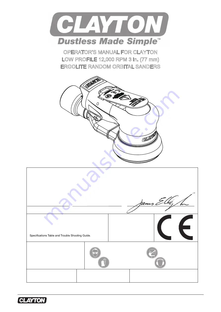
OPERATOR’S MANUAL FOR CLAYTON

LOW PROFILE 12,000 RPM 3 in. (77 mm)

ERGOLITE RANDOM ORBITAL SANDERS

Operator Instructions

Includes –Parts Page, Parts List, Please Read and Comply, 

Proper Use of Tool, Work Stations, Putting the Tool Into Ser-

vice, Operating Instructions and Compressor Layout, Service 

Tools and Accessories, Service Instructions, Back-Up Pads, 

Declaration of Conformity

CLAYTON Associates, Inc. 1650 Oak Street  Lakewood, NJ 08701 USA

declare on our sole responsibility that the products


 Place and date of issue 

Name 

Signature or equivalent marking of authorized person

Important

Read these instructions care-

fully before installing, operating, 

servicing or repairing this tool. 

Keep these instructions in a safe 

accessible location.

Manufacturer/Supplier

Required Personal Safety Equipment


Recommended Airline 

Size - Minimum


3/8 in 


10 mm

Recommended Maximum 

Hose Length


25 feet 


8 meters

Air Pressure

Maximum Working Pressure  90 psig  6.2 bar 

Recommended Minimum 

   NA  

   NA

Breathing Masks


Ear Protection

Safety Glasses


Safety Gloves

Lakewood, NJ  2019-04

James E. CLAYTON

CLAYTON Associates, Inc.

TEL (732) 363-2100   

www.VacuumSanding.com

3 in. (77 mm) Ergolite Random Orbital Sanders (See Product “Specifications” Table for particular Model) to which this declaration 

relates is in conformity with the following standard(s) or other normative document(s) EN ISO 15744:2008. Following the provisions 

of 89/392/EEC as amended by 91/368/EEC, 93/44/EEC & 93/68/EEC Directives and consolidating Directive 2006/42/EC

1

Copyright © 1984-2016 CLAYTON Associates, Inc. 

(732) 363-2100  • ww

w.VacuumSanding.com

B-X3CT30-8

Revision 2019-05

Summary of Contents for 770-12300J

Page 1: ...tions in a safe accessible location Manufacturer Supplier Required Personal Safety Equipment Recommended Airline Size Minimum 3 8 in 10 mm Recommended Maximum Hose Length 25 feet 8 meters Air Pressure Maximum Working Pressure 90 psig 6 2 bar Recommended Minimum NA NA Breathing Masks Ear Protection Safety Glasses Safety Gloves Lakewood NJ 2019 04 James E CLAYTON CLAYTON Associates Inc TEL 732 363 2...

Page 2: ...ican National Standards Institute Inc 1430 Broadway New York New York 10018 3 State and Local Regulations All CLAYTON Ergolite Random Orbital Sanders are warranted for defects in materials or workmanship for one year from the date of delivery to the user Combined with the CLAYTON name this Warranty expresses our total confidence in the superior quality durability and performance of the CLAYTON LP ...

Page 3: ... with the moving sanding pad in order to prevent pinching or cutting of hands or other body parts Wear suitable gloves to protect hands Never run the tool unless abrasive is applied to the workpiece There is a risk of electrostatic discharge if used on plastic and other non conductive materials Potentially explosive atmospheres can be caused by dust and fumes resulting from sanding or grinding Alw...

Page 4: ...er always ensure it is in place and in good working order when the tool is being operated 10 Vibration hazards Exposure to vibration can cause disabling damage to the nerves and blood supply of the hands and arms Wear warm clothing when working in cold conditions and keep your hands warm and dry If you experience numbness tingling pain or whitening of the skin in your fingers or hands stop using t...

Page 5: ...ing com B X3CT30 8 Revision 2019 05 ITEM 38 55 56 8 7 1 0 60 72 6 8 8 1 8 7 1 0 TORQUE SETTING in lbs N m 2 1 33 3 4 5 5 7 8 9 10 11 12 13 14 15 16 17 18 19 20 24 25 26 27 28 29 30 32 27 34 35 36 37 38 27 39 25 40 41 42 43 44 45 46 47 48 49 50 51 52 53 54 55 56 57 58 59 61 21 22 23 31 ...

Page 6: ... CONTACT BEARING 1SEAL 5001RS 1 19 673 A0016 SPACER 1 20 673 A2542 SPINDLE BEARING DUST SHIELD 1 21 673 A0017 BELLEVILLE WASHER 1 22 673 A0018 RETAINING RING 1 23 673 B0312 SPINDLE 1 24 673 G0108 GRIP 1 25 673 A0039 INTERNAL RETAINING RING 2 26 673 F0001 SPEED CONTROL 1 27 673 A0043 O RING 3 28 _ LEVER FOR CLAYTON ROS 3 32in ORBIT OPT 28 673 F0088 LEVER FOR CLAYTON ROS 3 16in ORBIT OPT 29 673 A003...

Page 7: ... A0007 VALVE 1 51 673 F0094 VALVE SPRING 1 52 673 G0011 END CAP 1 53 673 F0086 LOGO INSERT END CAP 1 54 673 A0044 14 0x1 5 O RING 1 55 673 A2475 INLET BUSHING ASSEMBLY ELITE 1 56 S6 0410A HEX SOCKET BUTTON HEAD SCREW M4x10 3 57 673 F0081 SNAP IN VAC COVER PLATE NV 1 58 673 G0035 3 SWIVEL EXHAUST FITTING Black SGV OPT 59 673 G0034 3 SWIVEL EXHAUST FITTING Black CV OPT 60 673 F0117 SWIVEL EXHAUST FI...

Page 8: ...rdance with EN 28662 1 Hand held portable power tools Measurement of vibration at the handle Part 1 General and EN 8662 8 1997 Hand held portable power tools Measurement of vibration at the handle Part 8 Polishers and rotary ergolite orbital and ergolite random orbital sanders Orbit Pad Face Model Number Vac Type Product Net Weight Pound kg Height inch mm Length inch mm Power HP watts Air Consumpt...

Page 9: ...to the tool Details of such equipment can be obtained from your supplier If such equipment is not used then the tool should be manually lubricated To manually lubricate the tool disconnect the airline and put 2 to 3 drops of suitable pneumatic motor lubricating oil such as Fuji Kosan FK 20 Mobil ALMO 525 or Shell TORCULA 32 into the hose end inlet of the machine Reconnect tool to the air supply an...

Page 10: ...ning Ring is completely snapped into groove in the Housing 3 Install the Valve Seat Valve and the Spring Coat the threads of the Inlet Bushing Assembly with 1 or 2 drops of Loctite 222 or equivalent non permanent pipe thread sealant Screw the Inlet Bushing Assembly into the inlet port on the Housing Torque to 60 in lbs 6 77 Nm Spindle Bearings and Shaft Balancer Assembly 1 Place the T 5A Spindle B...

Page 11: ... will not run freely If the pressed assembly is to loose the motor will not turn freely after assembly in the Housing 6 Secure the assembly by placing the Retaining Ring in the groove of the Shaft Balancer CAUTION The Retaining Ring must be placed so that the middle and two ends of tions must be securely snapped into the groove in the Shaft Balancer by pushing on the curved portions with a small s...

Page 12: ...ar ings See Shaft Balancer and Spindle Disassembly and Spindle Bearings Shaft Balancer Assembly Air leakage through the Speed Control and or Valve Stem Dirty broken or bent Valve Spring Valve or Valve Seat Disassemble inspect and replace worn or damaged parts See Steps 2 and 3 in Housing Disassembly and Steps 2 and 3 in Housing Assembly Vibration Rough Operation Incorrect Pad Only use Pad Sizes an...

Page 13: ......

Reviews: